The device and principle of operation of the hydraulic distributor
Consider the device of a four-line three-position distributor locked in the neutral position.
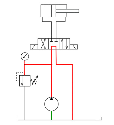
The principle of operation of the hydraulic distributor 44 of the scheme is shown in the video.
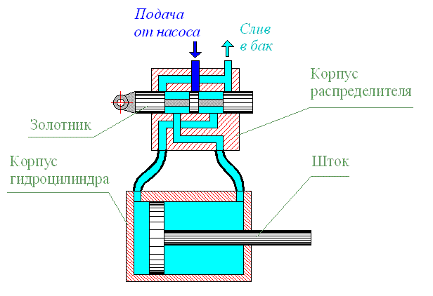
Channels for fluid supply are made in the distributor housing. The spool is installed in a hole bored in the body.
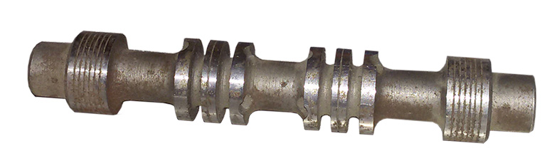
The distributor spool is a part, usually cylindrical, on which belts, grooves, grooves are made, necessary for separating or connecting various channels made in the distributor housing.
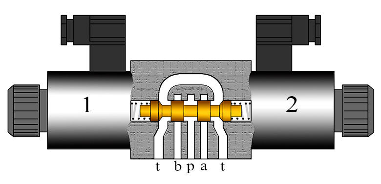
In the neutral position, the spool is held by means of springs, at which point it closes the P line. If a control signal is present, electromagnet 1 will move the spool to the right. In this position the spool will connect ports p and a, t and b. In the absence of a control signal, the springs will return the spool to the neutral position. If there is an electrical signal on electromagnet 2, the spool will move to the left, connecting channels p and b, t and a.
| Move spool to the left | Move spool to neutral position | Move spool to the right |
Classification of hydraulic engineering
These devices are divided based on the typology of locking structures. Hydraulic distributors, the types of devices of which differ in functionality, are divided into the following varieties:
- spools;
- crane distributors;
- with valve;
- jet;
- with a regulating element of the "nozzle-shutter" type.
Spool type distributors are very common. They are easy to manufacture, compact and reliable in operation. Withstand increased pressure up to 32 MPa and active flow, in contrast to the crane type.
The crane distributor is also quite widespread. Its valve design is based on the cylindrical shape of a rotary valve plug. But the faucet can also have a spherical, conical shape, and it can also be flat. A variety of types of locking elements makes this type of device very convenient and in demand.
Valve-based devices make it possible to avoid leakage of the working medium, which is often the case with spool valves. When the pressure exceeds 32 MPa, it is difficult to keep the hydraulic motor itself in a stationary position; position switching is required here. In this case, the valve distributor is relevant, which is characterized by increased weight and dimensions, completely seals the entire hydraulic line. This type of distributors is relevant where high tightness is needed. The locking structure, as a rule, is made in the form of a cone valve or a ball.
The “shutter-nozzle” device type works on the principles of a hydraulic pressure divider and qualitatively distributes the load during the flow of the working medium.
Inkjet options are characterized by reduced sensitivity to contamination, this is ensured by the complete absence of moving elements in the device.
Distributor breaker
How is the breaker-distributor arranged?
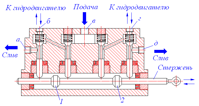
The breaker-distributor combines two devices: a breaker - interrupting (opening) the low voltage current circuit in the primary winding of the ignition coil in order to create an alternating magnetic field necessary to obtain a high voltage current in the secondary winding of the ignition coil, and a distributor - distributing the high voltage current by candles of engine cylinders in accordance with the order of its operation.The distributor-breaker (Fig. 1) consists of a housing 1, in which a shaft 2 is installed on a sliding bearing, which, with its lower spline 20, engages with the oil pump shaft and is driven from the camshaft gear. At the upper end of the shaft, a cam clutch 17 is freely installed, having the number of cams (faces) equal to the number of engine cylinders. The cam clutch is connected to the shaft through pins attached to the weights of the centrifugal ignition timing controller. A fixed disk 5 is fixed in the body of the interrupter, on which a movable disk 8 is mounted on a ball bearing. A fixed tungsten contact 4 is mounted on this disk, connected to the "mass" of the car. A movable tungsten contact is pressed against the fixed contact by a lamellar spring, fixed on a lever 18 isolated from the "mass". This lever has a textolite or plastic heel, with which it rests on the cam clutch. The leaf spring tends to keep the contacts closed, however, when the cam clutch rotates, its protrusion (face), running on the heel, removes the movable contact from the stationary one, thus opening the low voltage current circuit in the ignition coil. The movable contact, together with the lever, is isolated from the “ground” and is connected by wire 6 to the output terminal 7 and then by wire to the primary winding of the ignition coil. A current-carrying plate (rotor) 15 is installed on top of the cam clutch. An octane corrector 19 is installed in the lower part of the housing, the scale of which is graduated in degrees, and two nuts with a micrometric thread for fine tuning the octane corrector. A vacuum regulator 10 is attached to the breaker body on the side, the lever of which is connected to the movable disk of the breaker. A capacitor 9 is installed on the case or inside it. The breaker case is closed with a carbolite cover 11, in which contact plates are mounted connected to sockets 12 for installing high voltage wires in order to divert high voltage current to the spark plugs. The high voltage current from the ignition coil is fed by wire to the central terminal 13, in which the coal 14 is installed, loaded with a weak spring, due to which it is constantly pressed against the current-carrying plate 15. The distributor cover is pressed against the breaker body with spring latches 16.
Fig.1. Distributor breaker
How does a distributor breaker work?
When the shaft 2 rotates (Fig. 1), the cam clutch 17 rotates with it. When the face of the clutch runs on the heel of the movable contact lever, it moves away from the stationary one, breaking the low voltage current circuit. At the moment of greatest opening, the gap between the contacts should be within 0.35-0.45 mm. For its regulation, two screws are provided on the movable disk: adjusting eccentric and locking cylindrical. The gap is checked with a feeler gauge. With further rotation of the cam clutch, the face ceases to press on the heel of the lever and, under the influence of the leaf spring, the contacts close again, passing current into the primary winding of the ignition coil. With each opening, a high voltage current is induced in the secondary winding, which flows through the high voltage wire through the central terminal 13 of the distributor, coal 14, current-carrying plate 15, side electrode 12 of the distributor to the spark plug.
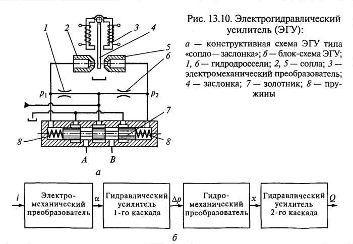
8.3. The device and principle of operation of the hydraulic distributor with electro-hydraulic control
Valve type
PG 73-2With
electro-hydraulic control
is a combination of control
distributor with electromagnetic
management
in the form of a pilot and the main
distributor with hydraulic
management,
which works in a similar way
distributor PG 72-3.
Three position
distributor
with electro-hydraulic control
(Fig. 3.12) consists of a body 2,
main spool 3,
lids 4
and 5,
springs 6
and 7,
ball valves 12,
chokes 13
and distributor pilot with electric
management 1.
Four way
performance
distributors (Fig. 3.13, a)
differ from five-way
(Fig. 3.13, b)
plug design 8
and 9,
(see Fig. 3.12) with which it is possible to
compound
drain channels T for four-way
or
disconnection for five-way
distributors.
supply
pressure to the ends of the main spool
channeled 16
and 17
from the control distributor 1.
As a control distributor
type hydraulic distributors are used
PG 73-1, and for distributors with
electro-hydraulic control
P and B types - P102 and BE type pilots
(PE) with electric control from
AC or DC.
Fig.3.12.
Three position hydraulic valve
with cylindrical spool
type
PG 73-2 with electrohydraulic control
Rice.
3.13. Graphic conventions
hydraulic distributor type PG 73-2
With
electro-hydraulic control
four-(a)
and five-way (b)
performance
hydraulic valve
works as follows. At
switched off electromagnets 14
and 15
pilot spool is in the middle
position and oil through the control channels
16
and 17
enters both end cavities
main spool 3,
and he springs 6
and 7
set to the middle position. At
turning on one of the electromagnets,
for example, the right one, one of the end
cavities (left) of the spool
3
connects to drain control line
T,
and the other (right) remains connected
with pressure control line
X (at
no traffic jam 10
pressure
control line
X
connects directly to the main
pressure line R).
As a result, the spool moves
to the extreme left position, compressing the spring
7
and displacing oil from the left cavity through
throttle 13
into the drain line.
At
spool switching 3
in the opposite position oil out
pressure line control line
enters under the end face of the main spool
through ball check valve 12.
Throttle control 13
you can set the speed of movement
spool, i.e. actuation time
separately in each direction. At
rotating it clockwise time
operation of the main spool
increases, and when rotating against
clockwise - decreases.
Prevention
To ensure the efficient operation of the tractor hydraulic system, it is necessary to follow the rules of operation and timely maintenance.
In the course of working with equipment equipped with hydraulics, its components should be regularly checked for malfunctions. The occurrence of a small-scale breakdown inevitably leads to the failure of other parts of the system. If this is found, it is immediately necessary to apply all available means to eliminate it:
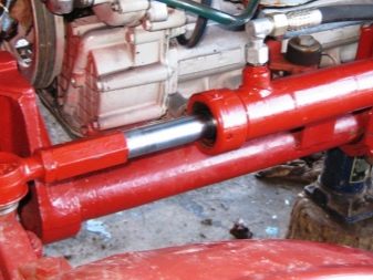
do not exceed the prescribed load on the hydraulic pump, hydraulic cylinders, oil hoses and other components;
avoid indicators of excessively high pressure, if necessary, dump it in a timely manner or select a suitable control valve;
to maintain the stable operation of the hydraulic mechanism, it is important to change / add fluid to the system in a timely manner: an insufficient amount of it will lead to a decrease in work efficiency and a quick failure of the unit;
all work on maintenance and repair of the system should be carried out with the tractor engine turned off (on a "cold") after pressure relief.
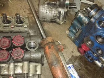
Table of common faults in hydraulic systems and how to fix them:
|
Malfunctions and their causes |
Remedy |
|
Fault: low lifting-pushing force of hydraulic cylinders or its complete absence. Cause: The oil level in the system has dropped. |
Add oil. |
|
An oil with unsuitable specifications has been used. |
Change the oil to the correct one. |
|
Oil filter or hydraulic cylinder dirty. |
Replace or wash the filter element. |
|
The presence of air in the system. |
Blow out the system - remove air, identify the point of entry and eliminate it. |
|
The presence of fluid leakage through worn seals. |
Replace seals with new ones. |
|
The operation of the relief valve, pressure is disrupted - jamming occurs in the open position. |
Flush/purge valve. Replace if necessary. |
|
Malfunction in the valves of the hydraulic distributor. |
Replace valves or their parts, if necessary, replace the entire block. |
|
Leaks in the docking nodes of the system. |
Check for leaks, fix found by crimping, tightening, installing clamps, replacing. |
|
Malfunction of the piston or oil seals of hydraulic cylinders. |
Check hydraulic cylinder for pressure leakage. Replace seals, piston. If necessary, change the node as a whole. |
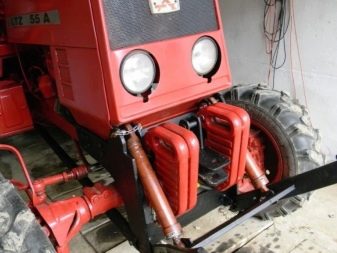
How to install hydraulics on a mini-tractor with your own hands, see the following video.
1. General information
During the operation of hydraulic systems,
the need to change direction
working fluid flow on individual
its sections in order to change direction
actuator movements
machines, it is required to provide the necessary
start-up sequence
these mechanisms, to unload
pump and hydraulic system against pressure and
etc.
These and some others
functions can be performed by special
hydraulic devices - guides
hydraulic distributors.
In the manufacture of hydraulic distributors
as building materials
apply steel casting, modified
cast iron, high and low carbon grades
steel, bronze. To protect individual
distributor elements from abrasive
wear, sliding surfaces
cementing, nitriding, etc.
Dimensions and weight of hydraulic valves
depend on the fluid flow through them,
with which they increase.
By connection method
to the hydraulic system hydraulic distributors
produced in three versions: threaded,
flanged
and butt
accessions. Choice of connection method
depends on the purpose of the hydraulic distributor
and flow through it of the working fluid.
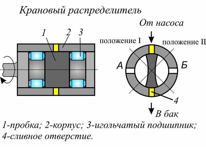
According to the design of the shut-off and control
element hydrodistributors
subdivided as follows:
Spool (shut-off and regulating
element is a cylindrical spool
or flat shape). In spool
control valves change
flow direction of the working fluid
carried out by axial displacement
locking and regulating element.
Crane (shut-off and regulating
the element is a crane). In these
control valves change
flow direction of the working fluid
achieved by turning the valve plug,
having a flat, cylindrical,
conical or spherical shape.
valve (shut-off and regulating
element is a valve). in valve
valves change direction
the flow of the working fluid is carried out
by sequential opening and
closing of working sections
valves (ball, poppet,
conical, etc.) of various designs.
By number of fixed positions
spool hydrodistributors
subdivided into two-position,
three-position and multi-position.
Management hydrodistributors
subdivided into hydraulic
manual, electromagnetic, hydraulic
or electro-hydraulic control.
Crane hydraulic distributors are used
most often as ancillary
in spool valves with
hydraulic control.