Calculation of the ventilation system
Normative supply air volume
Typically, natural ventilation systems are used in residential buildings. In this case, outside air enters the premises through transoms, vents and special valves, and its removal occurs through ventilation ducts. They can be attached or located in the internal walls. The construction of ventilation ducts in the external enclosing structures is not allowed due to the possible formation of condensate on the surface and subsequent damage to the structures. In addition, cooling can reduce the rate of air exchange.
Ensuring natural air flow through ventilation
The determination of the parameters of ventilation pipes for residential buildings is carried out on the basis of the requirements regulated by SNiP and other regulatory documents. In addition, the indicator of the multiplicity of exchange is also important, which reflects the efficiency of the ventilation system. According to him, the volume of air flow into the room depends on its purpose and is:
- For residential buildings - 3 m3/hour per 1 m2 of area, regardless of the number of people staying on the territory. According to sanitary standards, 20 m3/hour is sufficient for temporary residents, and 60 m3/hour for permanent residents.
- For auxiliary buildings (garage, etc.) - at least 180 m3 / hour.
To calculate the diameter of pipes for ventilation, a system with natural air flow is taken as the basis, without installing special devices. The easiest option is to use the ratio of the area of \u200b\u200bthe room and the cross section of the ventilation hole.
In residential buildings, 5.4 m2 of air duct cross section is required per 1 m2, and about 17.6 m2 in utility buildings. However, its diameter cannot be less than 15 m2, otherwise air circulation is not provided. More accurate data are obtained using complex calculations.
Algorithm for determining the diameter of the ventilation pipe
Based on the table given in the SNiP, the parameters of the ventilation pipe are determined based on the air exchange rate. It is a value that shows how many times during an hour the air in the room is replaced, and depends on its volume. Before determining the diameter of the pipe for ventilation, do the following:
- Calculate the volume of each room by multiplying its three dimensions.
- Determine the required volume of air according to the formula (separately for each room)
- Usually, for most rooms, either an exhaust or an inflow is normalized. In some rooms, it is necessary to ensure both the supply of air and its timely removal.
- All L values must be rounded up so as to obtain a multiple of 5.
- For those rooms where only supply or exhaust is needed, the calculated air volume is summarized separately.
- Make up a balance in which the total volume of inflow and exhaust must match.
- Having determined the required volume of air for the entire housing, the diameter of the exhaust pipe is found from the diagram. In this case, it should be taken into account that the speed in the central duct should not exceed 5 m/s, and in its branches - 3 m/s.
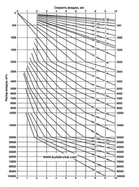
Diagram for determining the diameter of the ventilation pipe
Method of calculation
For general ventilation, the required
air exchange is determined from the condition
removal of excess heat and dilution
harmful emissions from fresh air
allowable concentrations. Ultimately
permissible concentrations of harmful substances
in the air of the working area set
according to GOST 12.1.005-88.
2.1.Estimated temperature value
supply air depends on
geographical location of the enterprise
take equal to 22.3 °C.
Air temperature in the working area
take 3 ... 5 ° C higher than the calculated
outside air temperature. Density
air, kg/m3, entering the
room,
 .(1)
.(1)
The excess amount of heat to be
removal from the production area,
determined by heat balance:
 ,(2)
,(2)
where
 is the heat supplied to the room from
various sources, kJ/h;
 -heat,
consumed (lost) by the walls of the building
and leaving with heated materials,
kJ/h
To the main heat sources
in industrial premises
relate:
-
hot surface equipment
(furnaces, drying chambers, pipelines
and etc.); -
equipment driven by electric motors;
-
solar radiation;
-
staff working on the premises;
-
various cooling masses (metal,
water, etc.).
Because the air temperature difference
inside and outside the building in a warm
period of the year is insignificant (3 ... 5 ° С), then
when calculating air exchange by excess
heat release heat loss through
building structures can be ignored.
At the same time, some increase in air exchange
positive effect on working conditions
working on the hottest days of the warm
period of the year.
With considering
formula (2) takes
the following view:
 .(3)
.(3)
In this design task, the excess
the amount of heat is determined
only taking into account heat dissipation
electrical equipment and operating
personnel:
 ,(4)
,(4)
where
 ,
,
-heat generated during operation
equipment electric motors, kJ/h;
 ,
,
- the heat given off by the worker
personnel, kJ/h.
Heat generated by electric motors
equipment,
 ,(5)
,(5)
where
β is a coefficient that takes into account the load
equipment, its simultaneity
work, mode
work; β = 0.25…0.35; N—total
installed power of electric motors,
kW.
The heat generated by the working staff
 (6)
(6)
where n is the number of employees, people; TOR- heat released by one person, KJ / h (taken
equal to 300 kJ/h in light work; at
moderate work 400 kJ/h;
during hard work 500 kJ/h).
2.2.Consumption
supply air, m3/h, required
to remove excess heat
 (7)
(7)
where
Qout of 6
— excess amount of heat, kJ/h;
With —
heat capacity of air, J / (kg-K);c=
1.2 kJ/(kg K); ρ is the air density,
kg/m3;toudis the temperature of the air being removed
from the premises, is taken equal to
air temperature in working
zone, °С; tetc
— supply air temperature, °C.
Supply air consumption, m3/h,
necessary to maintain
concentration of harmful substances in given
within,
 ,(8)
,(8)
where
G—
the amount of harmful substances emitted,
mg/h (see table); qoud
—concentration
harmful substances in the exhaust air,
which must not exceed the maximum
permissible, mg / m3, i.e.qoud
qMPC;qetc-concentration
harmful substances in the supply air,
mg/m3.
 (9)
(9)
2.3.Definition
required air exchange.
To determine the required air exchange
Lnecessary
compare valuesL1and L2calculated
according to formulas (1) and (8), and choose the largest
of them.
2.4. By
nomogram (Fig. 1) choose a fan
TsAGI series Ts4-70 No. 6 and identify it
main features: district
wheel speed ω,
m/s,
speed n,
rpm, efficiency η,
total pressure H
kgf/m2 (
mm water st)
2.5.Air exchange rate, 1/h,
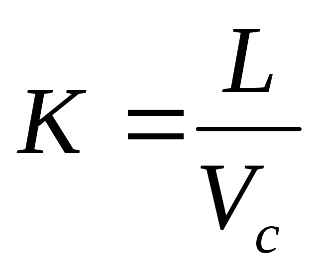 (10)
(10)
where L—required air exchange, m3/h; Vc-interior
free volume of the room, m3.
Room air exchange rate
usually ranges from 1 to 10 (large
values for rooms with significant
emissions of heat, harmful substances
or small in size).
For machine and instrument-making shops
recommended air exchange rate
is 1 ... 3, for foundries,
forging and pressing, thermal shops,
chemical industries - 3 ... 10.
2 Calculation of natural ventilation channels
Design
exhaust, natural ventilation
kitchens, sanitary facilities and bathrooms.
Natural exhaust solution scheme
ventilation of kitchens and sanitary facilities
separate isolated ventilation
channels. Exhaust openings are closed
louvered grilles, which have
on high
0.5÷0.7 m from the ceiling. Featured
louvre dimensions:
—
for kitchen 200250
mm;
—
for latrines and bathrooms 150150
mm;
—
for combined sanitary units 150200
mm.
V
brick buildings exhaust ducts
laid in
thicker walls. The size
channels is a multiple of brick size min
the size
140140
mm. Having arranged the channels in terms of a typical
floors, transfer them to the attic plan. By
each room is sized
the amount of air to be removed (table
11).
Table 11
Air exchange rates
and recommended sizes of ventilation ducts
|
A type |
Air exchange |
Featured |
Square |
deq, |
|
Kitchen with stove: two-burner three-burner four-burner |
60 75 90 |
140140 140270 140270 |
0,020 0,038 0,038 |
140 180 180 |
|
Toilet |
25 |
140140 |
0,020 |
140 |
|
Bathroom |
25 |
140140 |
0,020 |
140 |
|
Combined bathroom |
50 |
140270 |
0,038 |
180 |
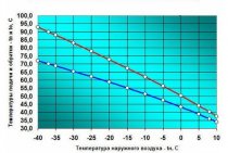
gravitational
natural pressure is determined
at outdoor temperature
equal to +5 ºС. At higher temperatures
room can be ventilated
using transoms or vents.
Calculation procedure:
1.
We determine the natural gravitational
pressure for channel natural
ventilation, kitchens with a three-burner
slab on the second floor. Aerodynamic
calculation starts with the most unfavorable
located channel - channel of the second
floors, output the channels as independent
korinnikov
 ,
,
 =1,27
=1,27
kg/m3,
where
 3,4
3,4
m - distance from the center of the exhaust
holes to mouth
exhaust shaft
(Fig. 14);
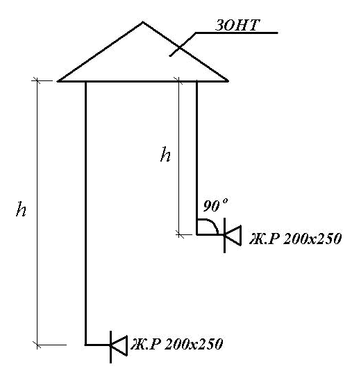
Fig.14.
 kg/m3;
 Pa.
Pa.
2.
Recommended air speed
in the channels of the upper floors = 0.5÷1.0 m/s.
Recommended
channel size is 140270
mm.
Square
channel 0.038 m2.
Diameter
equivalent deq=180
mm.
3.
Determine the air velocity in the channel
 m/s.
m/s.
4.
Determine the equivalent channel diameter
 mm.
mm.
5.
Determine friction pressure loss
per linear meter of air duct
adj. F
R=
0.035 Pa/m,
 m/s
m/s
at mm.
mm.
6.
Determine friction pressure loss
along the entire length of the brick channel, taking into account
channel roughness coefficient ,
,
determined by air speed m/s
m/s
(app.3)
 0,035·3,4·1,30=0,155
pa,
where
 - coefficient taking into account roughness
channel.
7. Define losses
pressure on local resistances (30)
 ,
,
where
 sum
sum
local resistance on the site (w / r
=1.2; elbow 90º = 1.2; probe over the shaft =1,3) 3,7
3,7
(Appendix I).
By
adj. We define
 according to the speed of air movement in the channel
 m/s
m/s
 Pa.
Pa.
8. Define
total pressure loss due to friction and
local resistance
 0,155
0,155
+0.677 = 0.832 Pa

 ,
,
2,0
> 0.832 Pa
General information
Ventilation - Organized and Regulated
air exchange to remove
from indoor air polluted
harmful impurities (gases, vapours,
dust), and the supply of fresh air into it.
According to the method of supplying fresh
air and removal of contaminated system
ventilation is divided into natural,
mechanical and mixed. By appointment
ventilation can be general and
local.
General ventilation is a system
ventilation designed for
supply of clean air to the room,
removal of excess heat, moisture and
harmful substances from the premises. In the last
case, it is applied if harmful
selections go directly to
room air, and workplaces are not
fixed and located throughout
room.
Usually air volume Letcsupplied to the premises during general exchange
ventilation, equal to the volume of airLv,
removed from the premises. However, in
clean shops of electrovacuum
production for which a large
the absence of dust matters, volume
more air flow
hoods, due to which some
excess pressure in the production
indoors to avoid dust
from adjacent rooms. In general
the difference between the volumes of inflow and
extract air must not exceed
10…15%.
In systems with mechanical drive
air movement through ducts
carried out by fans
create much more pressure
compared to the natural impulse.
This makes it possible to increase the speed
air movement, supply air to
greater distance and provide
smaller ducts.
Fan selection is carried out according to
aerodynamic characteristics,
which are compiled for each number
and fan type and express the dependence
between its performance
air, pressure and speed
working wheel. However, from various
types and numbers of fans are selected
the one whose efficiency is greater for the same
performance and pressure. Should
remember that the efficiency of the selected fan
must be at least 0.85 ήMax(ήMax—
maximum efficiency of the fan according to its
aerodynamic characteristics).
Peripheral speed of the impeller
centrifugal fan according to the condition
noiselessness should be no more than 25 m / s
for residential buildings and 17 m/s for clubs and
cinemas; circumferential speed of the worker
wheels of axial fans - no more
35 m/s for residential buildings and 25 m/s for clubs
and cinemas.
Consequences of poor ventilation
If the fresh air supply system is not properly organized in the premises, there will be a lack of oxygen and increased humidity. Mistakes in the design of the hood are fraught with the appearance of soot on the walls of the kitchen, fogging of windows and the appearance of fungus on the surface of the walls.
Fogging windows due to insufficient ventilation
It should be borne in mind that pipes of round or square section can be used for the installation of the ventilation system. When removing air without the use of special devices, it is advisable to install round air ducts, as they are stronger, tighter and have good aerodynamic characteristics. Square pipes are best used for forced ventilation.