Schematic diagrams of CO
V
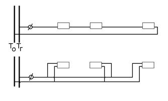
buildings for any purpose, 2 types are used:
two-pipe
single-pipe
V
two-pipe CO, each heating device is connected to the supply and
back stand. In two-pipe COs, hot water from the main
directly fed into each device. All devices work in parallel.
Tin=95C, Tout=70C.
V
single-pipe CO riser consists of one pipe, water flows in sequence
from the previous device to the next. Tin=105C, Tout=70C.
The water flow through each device is equal to the flow through the riser, and the temperature according to
as the coolant advances, it decreases.
By
laying method CO risers can
be vertical and horizontal
 |
Single pipe systems
With top wiring. They are arranged in buildings of any number of storeys in the presence of an attic.
|
|
I - flow riser; II, III - risers with axial and offset closing |
||
|
Vertical |
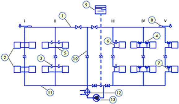
Most
cheap, hydraulically stable. When the hot water temperature drops
there is a relative increase in the heat transfer of the lower devices (up to 40%), with
As the flow rate decreases, the heat transfer of the lower appliances increases. Track.
Qualitative-quantitative adjustment is required. The presence of natural
circulation leads to self-regulating system.
Single pipe
syst. with bottom wiring settle down
in barren houses. The most low-cost, but due to the possible circulation in
devices at low flow rates, a decrease in flow rate is possible no more than 20%.
|
I - flow riser; II, III - risers with displaced closing sections; IV |
|||
|
Single pipe scheme |
V
in overturned systems, as the temperature decreases, the relative
heat transfer on the upper floors, the use of closing sections is unacceptable
(convectors are used).
Building heating design - Section 2. Building heating systems
Material content
-
Building heating design
-
thermal regime of the building. Winter air-thermal regime
-
Estimated winter outdoor temperature
-
Estimated winter outdoor temperature (continued)
-
Breathability restrictions. Moisture permeability of building structures
-
Summer air-thermal regime of the room
-
Thermal balance of the room
-
Heat loss
-
Heat loss (continued)
-
Specific thermal characteristic of the building
-
Building Specific Thermal Value (continued)
-
Section 2. Building heating systems
-
Heat carriers. Classification of heating systems
-
Classification of heating systems (continued)
-
Types and types of heating devices
-
Types and types of heating appliances (continued)
-
Selection, placement, connection of heating devices
-
Basic principles of heat engineering calculation of heating appliances
-
Water heating systems
-
Water heating systems (continued)
-
All pages
Page 12 of 20
Section 2. Building heating systems
1. General information about the heating system. Requirements for the heating system. Heat carriers heating system.
The heating system is:
a complex of elements designed to receive, transfer and transfer heat to heated rooms. The heating system consists of:
1. Heat generator (1).
2. Heat pipelines (2).
3. Heating (3).
The heat generator is used to receive heat and transfer it to the coolant.
Heat generators can serve:
1. Boiler installations at thermal power plants, IES.
2. Furnaces.
Heat pipelines - for transporting the coolant from the heat generator to the heaters. The heat pipes of the heating system are divided into pipelines, risers and connections (beds) to the devices.
Heaters - are used to transfer heat from the coolant to the air of heated rooms.
The main requirements for the heating system:
1. Sanitary and hygienic - providing SNiPs with temperatures at all points of the room and maintaining the temperatures of the internal surfaces of external fences and heaters at a certain level.
2. Economic - ensuring minimal costs for the manufacture and operation of the system (the possibility of unifying units, parts).
3. Construction - ensuring compliance with architectural, planning and design solutions. Linking the placement of heating devices with building structures.
4. Mounting - ensuring installation by industrial methods with the maximum use of unified units, with a minimum number of standard sizes.
5. Operational - simplicity and ease of maintenance, management, repair, reliability, safety, quiet operation.
6. Aesthetic - minimal area, compatibility with architectural solutions.
All of these requirements are important and must be taken into account when choosing and designing a heating system.
But the most important requirements still remain sanitary and hygienic requirements.
11 Heating
Heating - according to GOST R IEC 335-1 with the following additions.
11.2 Addendum to clause
The test is also carried out with the stone tank empty, provided that the sauna heater does not have a warning label regarding insufficient filling of the stone tank.
11.3 Addendum to clause
The temperature at the front of the sauna heater is measured by means of a wooden movable rod, as defined in Annex AA, placed vertically on the floor. The distance between the rod and the heater is the minimum horizontal distance marked on the heater.
NOTE If it is specified that the minimum horizontal distance varies with height from the floor, measurements should be taken accordingly.
11.7 Replacing an item
The devices are operated until steady state.
11.8 Addendum to clause
The temperature rise of the wooden rod, walls, ceiling and floor of the sauna room or factory-produced sauna should not exceed 115 °C.
In the sauna room, the temperature rise of handles, bell buttons and similar parts that are touched for a short time is increased by 20 °C.
Note - The ambient temperature is the temperature of the air outside the sauna room.
7 Markings and instructions
Marking and instructions - according to GOST R IEC 335-1 with the following additions.
7.1 Addendum to clause
Sauna heaters must be marked with the following:
"See instructions for additional important information."
In addition, they must be marked with the following:
-
— the minimum distance between the top of the heater and the ceiling of the sauna room;
-
- the minimum distance between the lower part (bottom) of the heater and the floor of the sauna room, provided that this distance is not determined by the design of the heater;
-
— the minimum horizontal distance between the heater and any combustible material in the sauna room, including the safety rail, provided that these distances are not determined by the design of the heater;
-
— the maximum depth and minimum width of the niche for sauna heaters designed to be installed in a niche.
Sauna heaters must bear the following boxed warning:
"ATTENTION! Covering causes a risk of fire."
The interior partitions of factory-made saunas must be marked in a frame near the sauna heater with the following warning:
"ATTENTION! Covering the heater causes a risk of fire."
The sauna heater must be marked in a frame with the following warning:
"ATTENTION! Insufficient filling of the stone tank causes a risk of fire.”
NOTE This warning is not required if the sauna heater according to Clause 11 is tested without stones in the tank.
7.7 Addition to point>’
Control panels must have a wiring diagram attached to the panel showing details of the electrical connections for the control and safety devices.
Notes
-
1 Connection diagrams may also show connections other than those required, provided that the additional information does not cause interference.
-
2 If more than one control panel is provided, the connection diagram can be divided as follows. so that each control panel has its own connection scheme and a link to other control panels.
7.12 Addendum to paragraph
The instruction manual for sauna heaters should indicate how to fill the stone tank.
The operating instructions for public sauna appliances that do not have a timer must state that the appliance must be monitored at all times. The operating instructions for other sauna heaters should state that the sauna room must be checked before the timer is restarted.
7.12.1 Addendum to clause
The instructions for installing factory-made saunas should contain detailed instructions on how to how to mount the device.
Installation instructions for other appliances must include the following:
-
- the minimum and maximum volume of the sauna room in cubic meters, in which the sauna heater can be installed;
-
- the minimum height of the sauna room;
-
- materials used for walls and ceilings in the sauna room;
-
- the location of individual protective rails, if any;
-
– means of ventilation of the sauna room;
-
- the possibility of installing adjacent sauna heaters or the statement that the sauna heater should be used alone;
-
- connection and position of control devices in the sauna room;
-
- installation of a control panel, including the statement that this control panel must be located outside the sauna room;
-
— the type of cable used to power the sauna heater.
In the installation instructions for public saunas that do not have a timer, it must be indicated that the control light indicating that. that the heater is turned on, should be in the duty room.
7.14 Addendum to paragraph
The indication of the distances to combustible materials in the sauna room must be clearly visible on the outside of the sauna heater without removing the casing.
Fire risk warnings must be visible after the sauna heater has been installed and the height of the signs must be at least:
5 mm - for capital letters;
3 mm - for lowercase letters.
Note - These warnings may be placed on the recessed bottom of the sauna heater.
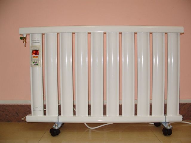
Electrical heating devices
All electrical appliances used when it is impossible to install a water heating system have different features and characteristics - from power to the principles of heat generation. At the same time, the main disadvantages of any such equipment are the high cost of operation and the need for an electrical network capable of withstanding heavy loads (with a total power of electric heaters of more than 9–12 kW, a network with a voltage of 380 V is required). Each variety has its own advantages.
convection appliances
The design that electric heating devices of this type have allows you to quickly heat the room with the help of air flows moving through them.
Air gets inside the devices through the holes in the lower part, it is heated using a heating element, and the exit is provided by the presence of upper slots. To date, there are electric convectors with a power of 0.25 to 2.5 kW.
Oil devices
Oil electric heaters also use the convection method of heating. Inside the case contains a special oil, which is heated by a heating element. In this case, the heating can be regulated using a thermostat that turns off the device when the air reaches the set temperature.
The features of the heaters is their high inertia. Due to this, the heaters heat up very slowly, however, even after a power cut, their surface continues to emit heat for a long period of time.
In addition, the surface of oil equipment heats up to 110-150 degrees, which is much higher than the parameters of other devices and requires special handling - for example, installation away from objects that can ignite.
The use of such radiators makes it possible to conveniently control the intensity of heating - almost all of them have 2-4 operating modes. In addition, taking into account the performance of one section of 150–250 kW, it is quite easy to select a device for a particular room. And the range of most manufacturers includes models with a power of up to 4.5 kW.
Fire safety requirements for the operation of heating appliances and systems
- Updated on 10/16/2014 08:53
- Posted on 09/09/2014 10:31
- Before the start of the heating season, stoves, boiler rooms, heat generating and air heater installations, other heating devices and systems must be checked and repaired. Faulty stoves and other heating devices are not allowed for operation.
- Furnaces and other heating appliances must have fire-prevention cuttings (retreats) from combustible structures established by the norms, as well as a pre-furnace sheet without burnouts and damage, not less than 0.5 x 0.7 m in size (on a wooden or other floor made of combustible materials).
- It is necessary to clean chimneys and stoves from soot before starting, as well as during the entire heating season at least:
once every three months for heating stoves; once every two months for furnaces and continuous hearths; once a month for kitchen stoves and other continuous (long-term) furnaces.
- On the fuel line to each nozzle of boilers and heat generating installations, at least two valves must be installed: one - at the furnace, the other - at the tank with fuel.
— During the operation of boiler houses and other heat-producing installations of enterprises and settlements, it is not allowed:
allow to work persons who have not undergone special training and have not received the appropriate qualification certificates; store liquid fuel in boiler rooms and heat generating rooms; use as fuel waste oil products and other flammable liquids and combustible liquids that are not provided for by the technical conditions for the operation of the equipment.
It is forbidden: to operate heat-producing installations in case of leakage of liquid fuel (gas leakage) from fuel supply systems; supply fuel with extinguished nozzles or gas burners; ignite installations without first purging them; work with faulty or disconnected control and regulation devices, as well as in their absence; dry any combustible materials on boilers and steam lines.
- During the operation of stove heating, it is prohibited:
leave unattended heating stoves, as well as entrust supervision of them to young children; place fuel, other combustible substances and materials on the pre-furnace sheet; use gasoline, kerosene, diesel fuel and other flammable and combustible liquids for ignition of stoves; to heat with coal, coke and gas furnaces not intended for these types of fuel; to fire furnaces during meetings and other public events in the premises; use ventilation and gas ducts as chimneys; reheat ovens.
- Furnace furnaces in buildings and structures should stop at least two hours before the end of work.
Ash and slag raked out of the furnaces must be spilled with water and removed to a safe place specially designated for them.
- Installation of metal furnaces that do not meet the requirements of fire safety standards and specifications is not allowed.
When installing temporary metal and other factory-made stoves in the premises of dormitories, administrative, public and auxiliary buildings of enterprises, as well as in residential buildings, the instructions (instructions) of the manufacturers of these types of products, as well as the requirements of design standards for heating systems, must be followed.
- The distance from stoves to goods, racks, showcases, counters, cabinets and other equipment must be at least 0.7 m, and from furnace openings - at least 1.25 m.
- In attics, all chimneys and walls in which smoke channels pass must be whitewashed.
Assistant to the Head for MP and Civil Defense and Emergencies
water system
The most commonly used and therefore have the widest range of heaters for water heating systems. This is due to their good efficiency and the optimal level of costs for the acquisition, installation and maintenance.
Structurally, the devices are not too different from each other. Inside each there are channels for the flow of hot water, the heat from which is transferred to the surface of the device, and then, with the help of convection, to the air of the room. For this reason they are called convection.
In water heating systems, the following types of radiators can be used:
- cast iron;
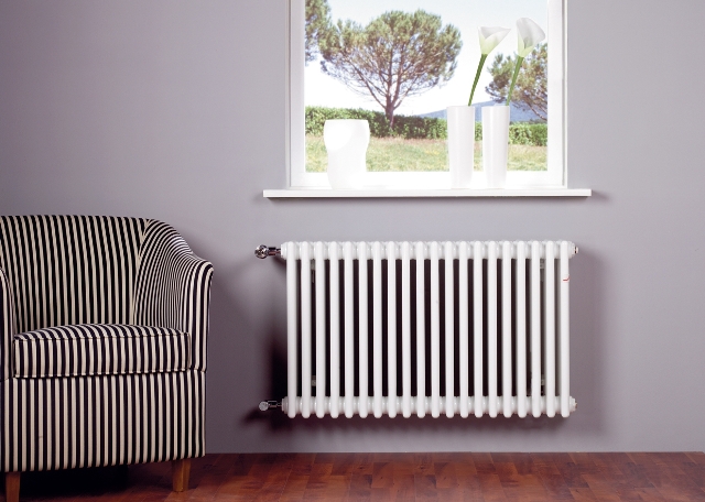
- steel;
- aluminum;
- bimetallic.
All these heaters have their own characteristics, due to which they are selected for each specific case, depending on the area of \u200b\u200bthe room, the nuances of installation, the quality and type of coolant (which is sometimes antifreeze).
Cast iron batteries
Cast iron was one of the most popular materials in domestic heating systems.His choice, as a rule, was due to the relatively low cost. Later, such devices began to be used less frequently, since they have a low heat transfer coefficient (only 40%), due to which the power of one section is approximately 130 watts. Although they can still be found in old-style systems. In a modern interior, designer models of cast-iron radiators are sometimes used.
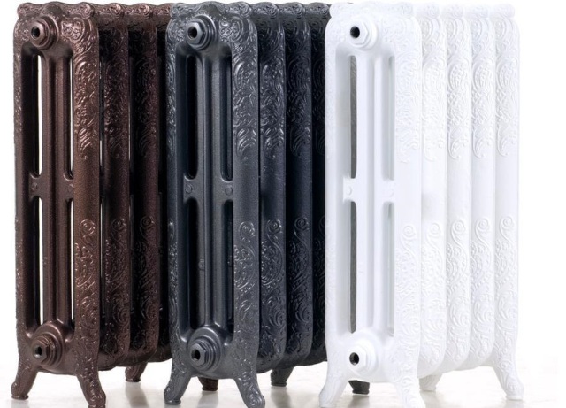
The advantages of such devices are a large surface area that gives off heat to the room, and a long service life (up to 50 years). Although there are still more disadvantages - they include a relatively large volume of coolant used (up to 1.4 liters), and the difficulty of repair, and the inertia of heating, due to which the temperature increase of the device is relatively slow, and even the need for periodic (at least once every 3 year) cleaning. In addition, heavy sections are very difficult to install.
Aluminum radiators
The use of aluminum radiators makes it possible to ensure the maximum level of heat transfer - the power of the section can reach 200 W (which is enough for heating 1.5–2 sq. M).
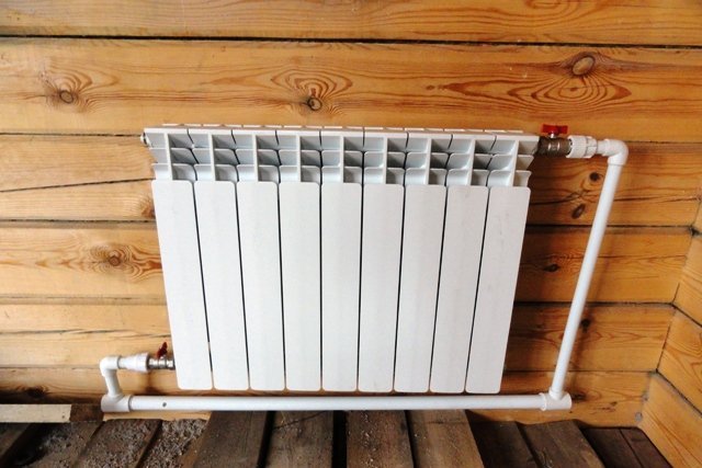
Their cost is quite affordable, and their light weight allows you to install yourself. True, the operation of the device is possible for only 20–25 years.
Bimetallic batteries
Their advantages include the presence in the design of convection panels that improve air circulation over the surface, ease of installation of devices for regulating the intensity of the coolant flow, as well as ease of installation. The radiator section, which has a power of up to 180 W, is capable of heating about 1.5 square meters. m area.
Despite the advantages that such heating devices have, there are problems in their use. So, for example, for bimetallic radiators, dilution of water with antifreezes is not recommended, which, although they do not allow the system to freeze, adversely affect the internal surfaces of heating devices.
Maintenance during the heating season
The operation of radiators during heating operation consists of several mandatory measures. First of all, when you turn on the heating (this is usually notified to management companies), you should not immediately put the device into operation.
This recommendation applies to district heating systems. In the off-season, heat supply organizations usually drain water to carry out repair and maintenance work on their networks.
The first supply of coolant to the general house heating system carries a lot of polluting components - corrosion products of steel pipes, dirt, sand, and so on. All this "good", of course, will be in the radiators of apartment owners. There is a risk of severe contamination of the radiator and a deterioration in the quality of its operation.
Therefore, the coolant flow through your radiators should be opened at least every other day, and preferably 2 after the start of heating the risers. When the radiator is turned off, the movement of the coolant occurs along the bypass, in addition to the device (with a single-pipe heating scheme).
It should be noted here that when carrying out pressure testing of the system, the radiator still needs to be connected to the risers - a leak test is necessary before the start of the heating season.
Many advise installing filters (mesh) on the radiator supply lines. Such advice can be treated with a great deal of skepticism - the purity of the coolant in domestic district heating networks is far from ideal. Most likely, during heating operation, especially at first, daily (if not hourly) cleaning of the filter will be required.
When the radiator is turned on, the taps should not be suddenly opened - this can cause a water hammer and lead to a rupture of the device. Details about hydraulic shocks in heating and measures to prevent them can be found in a special publication.
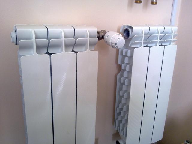
After turning on the radiators, it is necessary to periodically release them from the accumulating air by opening the Mayevsky tap.
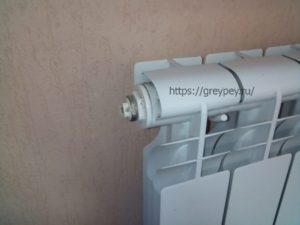 Manual radiator air vent - Mayevsky crane
During the first month, this operation should be carried out weekly, then every month. In the case of using automatic air vents, monthly check the operation of the devices.
When air is released from aluminum radiators, fire should not be brought to the outlets, smoking nearby, and the like - hydrogen released during the chemical reaction of the coolant and the radiator material is explosive.
With the constant accumulation of air in the radiator, it can be concluded that the device is not positioned correctly, check the horizontal position of the device using the building level and fix the problem in the off-season.
During the heating season, at least once a month, smooth opening / closing of shut-off valves should be performed. This will protect the working elements of ball valves from “sticking”, prevent the accumulation of deposits on the valve valves.
During the operation of heating devices - radiators, convectors and other devices, they are gradually polluted with dust carried by convective air currents. The accumulation of dust and dirt reduces the efficiency of heat transfer - therefore, periodically, as the heat-releasing surface gets dirty, it should be dry or wet cleaned. In this case, abrasive materials should not be used - they can damage the protective coating of heating devices.
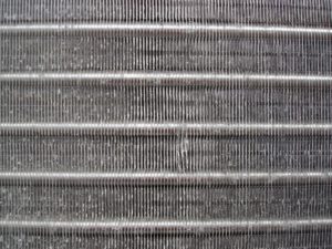 If the heat exchanger is dirty, the heat transfer of the convector is reduced
Cleaning is especially relevant for convectors - they have high-quality fins, which are highly prone to clogging.
It is also recommended to protect steel and cast-iron radiators from strong mechanical impacts, impacts with sharp objects. Cast iron is fragile, steel radiators have a section material thickness of 1.5 mm - they can simply be pierced.
This concludes the basic requirements for operating conditions - let's move on to the time when the heating does not work.
Question 9
Liberation
person from the action of electric
current.
Touch
to live parts under
tension, causes in most
cases of involuntary convulsions
muscle contraction. Therefore
fingers if the victim is holding the wire
hands, can clench so tightly that
free the wire from his hand becomes
impossible.
If
the victim continues to contact
with live parts, it is necessary
first of all quickly free him from
action of electric current
Wherein
keep in mind that touch
to a person who is under current, without
taking proper precautions
life-threatening for the caregiver.
Therefore, the first action of the renderer
help should be quick shutdown
the part of the installation to which
injured
At
the following must be taken into account:
1.
if the victim is on
altitude shutdown installation and release
injured by electric current
may cause the victim to fall.
from a height - in this case should be
security measures have been taken
fall of the victim;
2.
when the unit is turned off
turn off at the same time
electric lighting, and therefore
should provide lighting from another
source (lantern, torch, candles, emergency
lighting, rechargeable flashlights, etc.
etc.), without delaying, however, the shutdown
installation and assistance to the victim.
If
disabling the installation cannot be
produced quickly enough
take measures to separate the victim
from live parts to which it
touches.
On the
voltage up to 1000 volts.
For
separating the victim from current-carrying
parts or wire should be used
dry clothes, rope, stick, board
or any other dry object,
non-conductive electrical current.
The use of metal for this purpose
or wet items are not allowed.
To separate the victim from current-carrying
parts can also take up his clothes
(if it is dry and lags behind the body
victim), for example, for the floors of overalls
or a pea jacket, while avoiding touching
to surrounding metal objects
and parts of the body not covered by clothing.
Pulling the victim by the legs
should touch his shoes or clothes
without good isolation of their hands, since
shoes and clothes may be damp and
be conductors of electricity
current.
For
hand isolation assisting, especially
if necessary touch the body
the victim, not covered by clothes,
must wear dielectric gloves
or wrap your hands in a scarf, put on
on the hands of a cloth cap, put it on your hand
sleeve of overalls or pea coat, use
rubberized matter (raincoat) or simply
dry matter. You can also isolate
yourself, standing on a dry board or any
other non-conductive
bedding, bundle of clothes, etc.
At
separating the victim from current-carrying
parts, it is recommended to act according to
one-handed capabilities.
At
difficulty separating the victim
from live parts should be cut
or cut the wires with an ax with a dry
wooden handle or other
appropriate insulating tool.
It must be done with due
caution (without touching the wires,
cutting each wire separately,
wearing insulating gloves and
galoshes). On the
voltage above 1000 volts
On the
voltage above 1000 volts.
For
separating the victim from the ground or
live parts under
high voltage, should be worn
dielectric gloves and boots and
act with a barbell or pincers,
rated for the voltage of a given
installation.
On the
power lines when release
victim of the current by one of the indicated
above ways fast enough and
safe impossible, necessary
resort to a short circuit
and t
etc.) of all wires of the line and to a reliable
their preliminary grounding (according to
general safety regulations).
Action must be taken when throwing
precautions so that the thrown
the wire did not touch the body of the rescuer and
injured
Besides
In addition, keep in mind the following:
1.
if the victim is at a height,
should be warned or protected
his fall;
2.
if the victim touches one
wire, it is often sufficient
grounding of only one wire;
3.
wire used for grounding and
shorting, must first be connected
with the ground and then cast on the linear
wires to be grounded.
Should
also know that after shutdown
lines on it in case of large capacity
lines may remain charged, dangerous
for life, and what can secure the line
only its reliable grounding.