Shut-off valves
-
Main article: Shut-off valves
Shut-off valves are used to turn on and off the boiler unit, its elements and individual sections of pipelines during the operation of the boiler plant. She works intermittently. The main requirement for shut-off valves is to provide shutoff tightness in the closed state and to provide minimal resistance to the flowing medium in the open state. Shut-off valves include taps, valves, gate valves and butterfly valves. Shut-off valves are produced both with manual and electric drive. In boiler plants of medium and high power, electrically operated shut-off valves are mainly used.
Rated pressure
The letters PN are the designation of the permitted working pressure. The next figure indicates the level of internal pressure in bar that the product can withstand during a service life of 50 years at a water temperature of 20 degrees. This indicator directly depends on the wall thickness of the product.
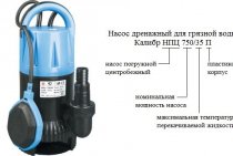
PN10. This designation has an inexpensive thin-walled pipe, the nominal pressure in which is 10 bar. The maximum temperature that it can withstand is 45 degrees. Such a product is used for pumping cold water and underfloor heating.
PN16. Higher nominal pressure, higher limiting liquid temperature - 60 degrees Celsius. Such a pipe is significantly deformed under the influence of strong heat, therefore it is not suitable for use in heating systems and for supplying hot liquids. Its purpose is cold water supply.
PN20. The polypropylene pipe of this brand can withstand a pressure of 20 bar and temperatures up to 75 degrees Celsius. It is quite versatile and is used to supply hot and cold water, but should not be used in a heating system, since it has a high coefficient of deformation under the influence of heat. At a temperature of 60 degrees, a segment of such a pipeline of 5 m is extended by almost 5 cm.
Requirements for dyes
The coloring with which decals are applied must be resistant to chemicals and weather conditions, since marking of communications is necessary both in the industrial sector and in residential complexes. GOST 14202-69 does not apply to electrically conductive networks.
There are several ways to apply paint to systems.
The continuous painting method is applied if the pipeline is short and consists of a small number of connections.
With a large number of components of wired networks, long kilometers, and also if the architecture of the building does not imply large areas of coloring, coloring is used in separate fragments. The rest of the pipeline is tinted to match the color of the walls, ceiling, floor, etc. In the case when communications are located outside buildings and structures, the color should reduce the thermal effect on the pipes.
The size of the coating also depends on the outer diameter of the pipes. In the event that the diameter is large, the color designation is applied in the form of stripes with a height of at least 1/4 of the pipe circumference.
According to GOST, the paint is applied to the most important and critical areas, for example, at the joints and passage of pipes through walls, ceilings, floors, etc., at flanges, at points of selection and control, in the area of \u200b\u200bentrance and exit to the room and from it after 10 -meter sections inside the building and after 30-60 m outside.
Important!
On pipelines with increased pressure, connecting flanges are subject to painting, since the linear systems themselves are in protective casings.
Marking communications with various devices
In the event that the contents of communications are particularly aggressive, warning rings are applied to them in one of three colors: red corresponds to flammability, flammability and explosiveness; yellow color - dangers and harmfulness (toxicity, radioactivity, the ability to cause various types of burns, etc.); the green color with a white border corresponds to the safety of the internal content. The width of the rings, the distance between them, the application methods are standardized by GOST 14202-69.
Network marking is possible with the help of stickers. In the event that the sticker contains text, it is made in a clearly distinguishable font, without unnecessary symbols, words, abbreviations, in the maximum accessible syllable. Fonts comply with GOST 10807-78.
Stickers are also made in the form of arrows showing the direction of the flow of the substance inside the pipe. Arrows are also standardized in terms of size
The designation on the arrows is differentiated: “flammable substances”, “explosive and fire hazardous”, “poisonous substances”, “corrosive substances”, “radioactive substances”, “attention - danger!”, “flammable - oxidizer”, “allergic substances ". The color of the arrows, as well as the inscriptions, is applied in black or white, in order to achieve the greatest contrast with respect to the main coating of the pipe.
With a particularly dangerous communication component, stickers are made in the form of warning signs (in addition to color rings). The signs are triangular in shape with a black image on a yellow background.
Important!
In plumbing systems with hot water and in the case of transporting leaded gasoline, the inscriptions must be white.
If the contents of the pipeline can damage the color designation, change its shade, special shields are used as additional markings, which are informative in nature, numerical and alphabetic. The requirements for the graphics of the shields are identical to those of the stickers. Dimensional characteristics of the shields correspond to the characteristics of the arrows. Marking boards should be located in clearly visible places, if necessary, illuminated by artificial lighting without interference for viewing by maintenance personnel.
Reading information
- The name of the manufacturer usually comes first.
- Next comes the designation of the type of material from which the product is made: PPH, PPR, PPB.
- On pipe products, the working pressure must be indicated, which is indicated by two letters - PN, - and numbers - 10, 16, 20, 25.
- Several numbers indicate the diameter of the product and the wall thickness in millimeters.
- On domestic modifications, the class of operation in accordance with GOST may be indicated.
- The maximum allowed.
Additionally indicated:
- Regulatory documents in accordance with which pipe products are manufactured, international regulations.
- Quality mark.
- Information about the technology by which the product is made, and the classification according to MRS (Minimum Long-Term Strength).
- 15 digits containing information about the date of production, batch number, etc. (the last 2 are the year of issue).
And now let us dwell in more detail on the most important characteristics of polypropylene pipes indicated in the marking.
Control armature
-
Main article: Control armature
Control fittings are used to monitor the movement of the product and determine its level. It includes trial and three-way valves, level indicators, etc.
Pipe fittings are made of cast iron, carbon and alloy steels, non-ferrous metals and alloys, etc. In boiler plants, steel and cast iron fittings are mainly used. The limits of the use of cast iron and steel fittings according to the rules of Gosgortekhnadzor and SNiP І-G.7-62 are given in the table below.
According to the design of connection to pipes and equipment, flanged, coupling, pin and welded fittings are manufactured.
The most common in boiler plants is flanged fittings, as it allows during operation to disassemble, clean and repair piping systems.
Coupling fittings have an internal thread at the connecting ends. They produce such fittings with Dat up to 80 mm and are used for pipelines on ru up to 10 kgf / cm².
For the installation of control and automation devices, pin fittings with a diameter of up to 20 mm are produced, the connecting ends of which are cut from the outside.
In pipelines that do not require disassembly and transport low-aggressive products, welded fittings are used.
Limits of the use of cast iron and steel fittings for intrashop networks
| Dy mm (up to) | Rebar material | Parameter values for intrashop pipelines | |
|---|---|---|---|
| p slave' kgf/cm² | t v'°С | ||
| 200 | Gray cast iron | 13 | 300 |
| 400 | Gray cast iron | 13 | 200 |
| 500 | Gray cast iron | 13 | 150 |
| 300 | Gray cast iron | 8 | 300 |
| 500 | Gray cast iron | 8 | 200 |
| 600 | Gray cast iron | 8 | 150 |
| 500 | Gray cast iron | 5 | 300 |
| 200 | Gray cast iron | 2,5 | Any |
| 80 | malleable iron | 40 | 400 |
| 100 | malleable iron | 25 | 300 |
| 250 | malleable iron | — | — |
| Any | Carbon steel | 64 | 400;450 |
Notes: 1. When laying pipelines above ground, it is not allowed to install fittings made of ductile iron - at an air temperature below -30 ° C and from gray cast iron - below - 10 ° C. In these cases, steel fittings must be installed.
2. It is allowed to install fittings made of gray cast iron on drainage and condensate lines of pipelines.
Individual heating point. Principle of operation
The central heat point, which is the source of the heat carrier, supplies hot water to the inlet of the individual heat point through the pipeline. Moreover, this liquid in no way enters any of the building systems. Both for heating and for heating water in the DHW system, as well as for ventilation, only the temperature of the supplied coolant is used. Energy is transferred to the systems in plate-type heat exchangers.
The temperature is transferred by the main coolant to the water taken from the cold water supply system. So, the cycle of movement of the coolant begins in the heat exchanger, passes through the path of the corresponding system, giving off heat, and returns through the return main water supply for further use to the enterprise providing heat supply (boiler room). The part of the cycle that provides for the release of heat heats the dwellings and makes the water in the taps hot.
Cold water enters the heaters from the cold water supply system. For this, a system of pumps is used to maintain the required level of pressure in the systems. Pumps and additional devices are necessary to reduce or increase the water pressure from the supply line to an acceptable level, as well as its stabilization in the building systems.
Disadvantages of central heating
The traditional scheme of centralized heating works like this: from the central boiler house, the coolant flows through the mains to the centralized heating unit, where it is distributed through intra-quarter pipelines to consumers (buildings and houses). The temperature and pressure of the coolant is controlled centrally, in the central boiler house, with uniform values for all buildings.
In this case, heat losses are possible on the route, when the same amount of coolant is transferred to buildings located at different distances from the boiler house. In addition, the architecture of the microdistrict is usually buildings of various heights and designs. Therefore, the same parameters of the coolant at the outlet of the boiler room do not mean the same input parameters of the coolant in each building.
The use of ITP became possible due to changes in the heat supply regulation scheme. The ITP principle is based on the fact that heat regulation is carried out directly at the inlet of the heat carrier into the building, exclusively and individually for it.To do this, heating equipment is located in an automated individual heat point - in the basement of the building, on the ground floor or in a separate building.
Determination of ITP individual heating point
According to the textbook definition, an ITP is nothing more than a heat point designed to serve the whole building or its individual parts. This dry formulation needs some explanation.
The functions of an individual heating point are to redistribute the energy coming from the network (central heating point or boiler room) between ventilation, hot water and heating systems, in accordance with the needs of the building. This takes into account the specifics of the premises served. Residential, warehouse, basement and other types of them, of course, should differ in temperature conditions and ventilation parameters.
Installation of ITP implies the presence of a separate room. Most often, the equipment is installed in the basement or technical rooms of high-rise buildings, extensions to apartment buildings or in separate buildings located in close proximity.
Modernization of the building by installing ITP requires significant financial costs. Despite this, the relevance of its implementation is dictated by the advantages that promise undoubted benefits, namely:
- coolant consumption and its parameters are subject to accounting and operational control;
- distribution of the coolant throughout the system depending on the conditions of heat consumption;
- regulation of the coolant flow, in accordance with the requirements that have arisen;
- the possibility of changing the type of coolant;
- increased level of safety in case of accidents and others.
The ability to influence the process of coolant consumption and its energy performance is attractive in itself, not to mention the savings from the rational use of thermal resources. The one-time costs of ITP equipment will more than pay off in a very modest period of time.
The structure of an ITP depends on which consumption systems it serves. In general, it can be equipped with systems for providing heating, hot water supply, heating and hot water supply, as well as heating, hot water supply and ventilation. Therefore, the ITP must include the following devices:
- heat exchangers for the transfer of thermal energy;
- valves of locking and regulating action;
- instruments for monitoring and measuring parameters;
- pump equipment;
- control panels and controllers.
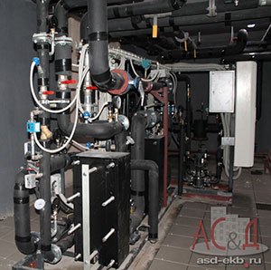
The scheme of the heating substation is built using a plate heat exchanger and is completely independent. To maintain the pressure at the required level, a dual pump is installed. There is a simple way to “re-equip” the circuit with a hot water supply system and other units and units, including metering devices.
The operation of the ITP for hot water supply implies the inclusion in the scheme of plate heat exchangers that operate only on the load on the hot water supply. Pressure drops in this case are compensated by a group of pumps.
In the case of organizing systems for heating and hot water supply, the above schemes are combined. Plate heat exchangers for heating work together with a two-stage DHW circuit, and the heating system is replenished from the return pipeline of the heating network by means of appropriate pumps. The cold water supply network is the feeding source for the DHW system.
If it is necessary to connect a ventilation system to the ITP, then it is equipped with another plate heat exchanger connected to it. Heating and hot water continue to work according to the previously described principle, and the ventilation circuit is connected in the same way as a heating circuit with the addition of the necessary instrumentation.
3. Process pipelines
3.3.1. General safety requirements associated with the construction and placement of technological pipelines, equipment, valves must comply with SNiP 3.05.05-84.
Technological pipelines (parts and fittings) are subject to testing for tightness and strength in accordance with the requirements of SNiP 3.05.05-84.
3.3.2. For pipelines of pumping and filling stations, a technological diagram of the location of underground and surface pipelines and locking devices installed on them should be drawn up.
It is not allowed to change the current layout of pipelines without the permission of the chief engineer of the association.
Pumps used for pumping flammable liquids must be equipped with:
interlocks that exclude start-up or stop operation in the absence of a pumped liquid in its body or deviations of the upper and lower levels of liquids in the receiving and supply tanks from the maximum allowable values;
means of warning signaling about violation of operating parameters that affect safety.
3.3.3. Pipelines of explosive technological systems should not have flange or other detachable connections, except for the places where fittings are installed or devices are connected.
3.3.4. On the discharge pipeline of centrifugal pumps and compressors, a check valve or other device must be provided to prevent the movement of pumped liquids in the opposite direction and, if necessary, a safety device (valve).
The shut-off and control equipment must be numbered corresponding to the executive technological schemes.
Stop valves (gate valves, taps) installed on pipelines must have end position indicators.
3.3.5. Over the condition of hangers and supports of pipelines laid above the ground, supervision should be established in order to avoid their dangerous sagging and deformation, which can cause an accident.
3.3.6. In places where workers cross pipelines, transition platforms or bridges with railings should be arranged.
3.3.7. Trays and trenches must be covered with slabs of non-combustible material.
3.3.8. Trays, trenches and wells on pipelines must be kept clean and regularly cleaned and flushed with water.
Shut-off valves located in wells, chambers or trenches (trays) must have drives that allow them to be opened (closed) without the worker descending into the well or trench (tray).
3.3.9. Use crowbars, pipes, etc. to open and close pipeline fittings. prohibited.
3.3.10. If there are dead-end sections on the pipelines, they must be systematically monitored. In the winter period of the year, measures should be taken to prevent their freezing.
3.3.11. The use of open flames (bonfires, torches, blowtorches, etc.) for heating pipelines and fittings is not allowed. Warming can only be done with hot water, steam or heated sand, while the heated area must be disconnected from existing pipelines.
3.3.12. Cleaning of plugs formed in pipelines with steel bars and other devices that can cause sparking from friction or blows against the pipe is not allowed.
3.3.13. Operation of pipelines using non-standard fittings and fittings is not allowed.
3.3.14. Flexible hoses must not be used in explosive technological systems.
3.3.15. During the pumping of oil products, any work on the repair of pipelines and their fittings is not allowed.
3.3.16. Pipelines for petroleum products must be grounded to discharge static electricity.
In the absence of washers made of dielectric materials and washers painted with non-conductive paints in flanged connections of pipelines, reliable grounding of pipelines is ensured by their connection to grounded tanks.
zakonbase.ru
Benefits of using ITP
The four-pipe heat supply system from the central heating point, which was previously used quite often, has a lot of disadvantages that are absent from the ITP. In addition, the latter has a number of very significant advantages over its competitor, namely:
- efficiency due to a significant (up to 30%) reduction in heat consumption;
- the availability of devices simplifies the control of both the flow of the coolant and the quantitative indicators of thermal energy;
- the possibility of flexible and prompt influence on heat consumption by optimizing the mode of its consumption, depending on the weather, for example;
- ease of installation and rather modest overall dimensions of the device, allowing it to be placed in small rooms;
- reliability and stability of the ITP, as well as a beneficial effect on the same characteristics of the serviced systems.
This list can be continued indefinitely. It reflects only the main, lying on the surface, the benefits obtained by using ITP. It can be added, for example, the ability to automate the management of ITP. In this case, its economic and operational performance becomes even more attractive to the consumer.
The most significant disadvantage of ITP, apart from transportation and handling costs, is the need to settle all sorts of formalities. Obtaining appropriate permits and approvals can be considered a very serious task.
Types of coatings
To cover linear systems, a paintwork material is used that corresponds to GOST and depends on the internal component, the physico-chemical composition of the pipes, their insulating characteristics, and also on the cost of the paint.
In rooms where there is no aggressive environment, good ventilation is established, it is possible to use enamels in accordance with technical documentation.
Marking must be carried out strictly in accordance with safety regulations in order to avoid accidents and injury hazards.
Periodically, all marking products are subject to renewal to restore the original color.
Below are answers to the most common questions about marking pipelines for industrial and civil facilities.
What color should the pipelines be painted in the central heating station, ITP, boiler room?
According to GOST 14202, the marking of pipelines does not depend on the object, but depends on the substance in the pipeline.
Pipelines with the transported substance WATER are painted green, STEAM - red, AIR - blue, GAS - yellow, ACIDS - orange, ALKALINE - purple, LIQUIDS - brown, OTHER - gray.
How to mark pipelines in the central heating station, ITP, boiler room?
The most common substances in the pipelines of the central heating substation/ITP/boiler rooms are water, steam, and gas.
The pipeline with water should be painted green, with steam - red, with gas - yellow. Identification coloring is allowed to be applied in sections.
It is also necessary to indicate the name and direction of movement of the substance using or . Their color must be the same as that of the identification markings. The locations of the shields are regulated by regulatory documentation.
What color should the hot/cold water/coolant pipes be painted?
All pipelines transporting substances whose main component is water are painted green in accordance with.
If you mark the pipelines in accordance with, then the supply and return pipelines are painted green (if the coolant is water).
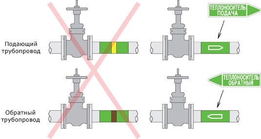
To identify the supply and return pipelines, appropriate designations with the direction of movement and the inscription should be used, for example “HEATING CARRIER SUPPLY”
The requirement to mark the supply pipeline of the heating network with a yellow ring on a green background, and the return pipeline - with a brown ring on a green background, is borrowed from the now inactive “Typical instructions for the operation, repair and control of stationary pipelines of network water RD 34.39.501, TI 34-70-042- 85” and was valid only for network water pipelines that are on the balance sheet of power plants.
The current regulatory documentation for marking pipelines with coolant refers exclusively to the requirements of GOST 14202.
How to mark gas pipelines correctly?
Pipelines transporting any gases are painted yellow in accordance with.
Specify the name of the gas and the direction of movement by means of or .
It is also necessary, depending on the parameters of the gas, to apply red or yellow warning rings (Table 3, ), and if the gas has a dangerous property (flammability, toxicity, oxidizing agent), then an appropriate hazard sign must be applied.
How to mark steam pipelines?
Steam pipelines must be painted red and put on a red shield with the name and direction of its movement.
If the pressure in the steam pipeline is more than 1 kgf / cm² and the temperature of St. 120C, a yellow warning ring must be applied over the paint. With an increase in steam parameters, the number of applied rings increases (see Table 3
GOST 14202-69 has the status of a valid document.
What materials should be used when marking pipelines in accordance with GOST 14202-69?
There are also no documents prohibiting marking with self-adhesive tapes and PVC-based markers.
Moreover, the use of self-adhesive materials is more expedient (generally accepted all over the world) - more convenient, faster, more accurate, allows you to more accurately comply with the important requirements of GOST for color, size, font and shape.
7.4. All equipment, including pipelines
1.7.4. All main and auxiliary equipment, including pipelines, bus systems and sections, as well as fittings, gas and air pipeline dampers, must be numbered. In the presence of a selective control system (ISS), the numbering of the valves in place and on the executive diagrams must be double, indicating the number corresponding to the operational scheme and the number according to the ISU. The main equipment must have serial numbers, and the auxiliary equipment must have the same number as the main one, with the addition of the letters A, B, C, etc. The numbering of the equipment must be made from the permanent end of the building and from row A. On double blocks, each boiler must be assigned a block number with the addition of the letters A and B. Individual links of the fuel supply system must be numbered sequentially and in the direction of fuel movement, and parallel links - with the addition to these numbers of letters A and B along the course of fuel from left to right.
PTE requirements on the ordering of the numbering of all main and auxiliary equipment, pipelines, valves, gates, systems and sections of tires, etc. are necessary in order to ensure the correctness of operational orders and the accuracy of the execution of these orders at the site when performing operational work - switching, checking equipment, testing, repairs, etc.
For the purpose of compact and economical placement of devices on equipment control panels at power units, a selective control system (MCS) is used, which provides individual control from one key on the control panel to dozens of shutoff valves, depending on the capacity (number of numbers) of the dialer. The fittings connected to such a system have a double numbering; in addition to the usual number according to the operational scheme, it is also assigned a number according to the ISU.
Numbering and symbols make it possible to shorten entries in technical documentation and specify operational instructions.So, for example, the entry “Stop blower fan No. 3A” means that blower fan “A” of the third boiler unit should be stopped; a shorter form is possible: "Stop DV-ZA". The entry “Turn off the sectional switch between the 2nd and 3rd sections of the 6 kV buses” can be done as follows: “Turn off SV2-3 - 6 kV”.
It is recommended to mark shut-off and control valves, gate valves according to the following principle: separate, starting from the first number for each unit, the numbering of valves, valves and gates separately for steam pipelines, feed lines, air ducts and gas ducts, dust and fuel oil pipelines. Gate valves of the same name, gate valves and valves of all units must have the same number. For example, the main steam valve of all boiler units must have the same number, the damper behind the smoke exhauster of all boiler units must have the same number (the ninth gas damper of the fourth boiler), etc. Other principles can be used for numbering, for example, for steam valves, the letter “P” is added, for valves on feed water, the letter “B”, for valves on circulating water, the letter “C”, etc.
The designation and numbering system must comply with the requirements of the rules of the State Energy Supervision Authority and the PUE.
foraenergy.ru