Method for calculating a simple pipeline.
First case:
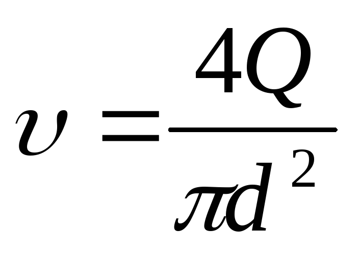
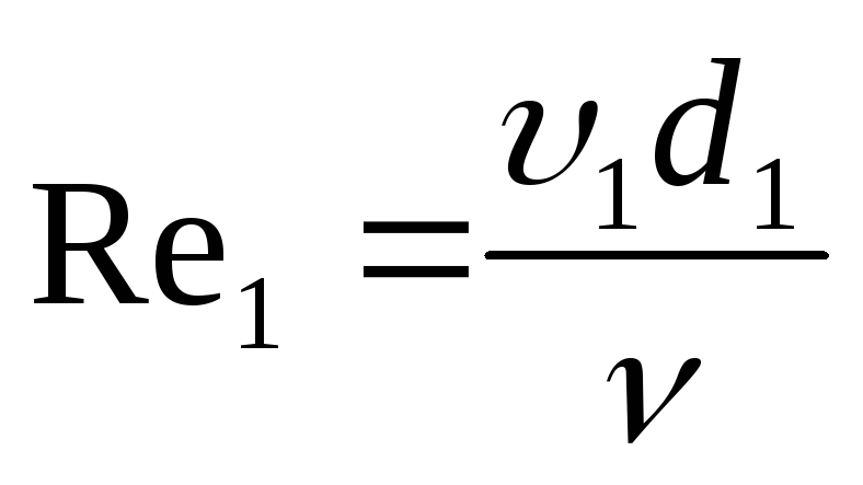
We have
simple pipeline with permanent
diameter
 ,
,
who works under pressure
 .
.
Rice. 41 Calculation scheme
direct pipeline (case one)
For
sections 1 - 1
and 2 - 2 we will write
Bernoulli equation:
 .
.
Because
 ,
,
pressure ,
,
then the equation will take the form:
 (119)
(119)
Since we have
hydraulically long pipeline, then
disregarding local resistance,
we get
 (120)
(120)
where
 and
and .
.
Taking into account local
losses
 (121)
(121)
Second case:
The pipeline consists
from pipes connected in series
different diameters.

Rice. 42 Calculation scheme
simple pipeline (case two)
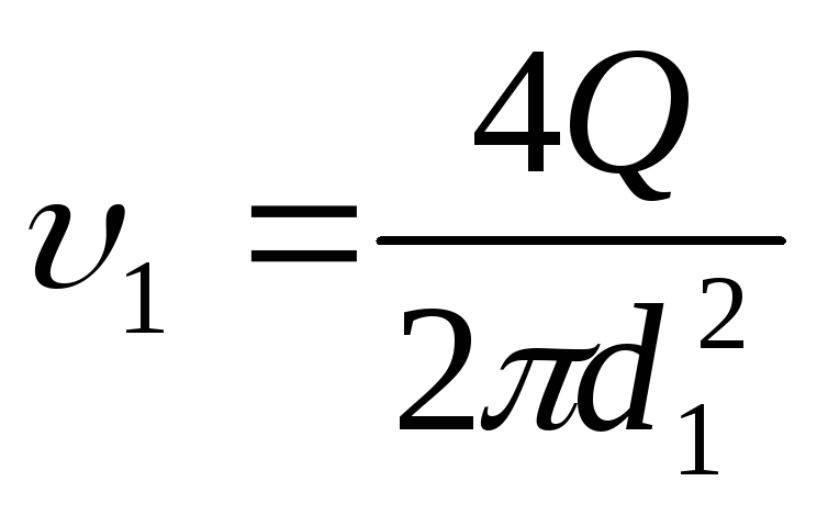
Three lengths
 ,
, ,
, with equal pipe diameters
 ,
, ,
,
 .
.
The pressure will be spent on overcoming
head loss along the length:
 (122)
(122)
loss on any
plot is determined by the formula:
 (123)
(123)
then
 (144)
(144)
or
 (145)
(145)
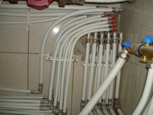
Forced circulation systems
Such systems usually operate on gas or electric boilers. The diameter of the pipes for them should be chosen as small as possible, since the forced circulation is provided by the pump. The feasibility of small diameter pipes is explained by the following factors:
- a smaller section (most often these are polymer or metal-plastic pipes) allows minimizing the volume of water in the system and, therefore, accelerating its heating (the inertia of the system decreases);
- installation of thin pipes is much easier, especially if they need to be hidden in the walls (making strobes in the floor or walls requires less labor);
- pipes of small diameters and connecting fittings to them are cheaper, therefore, the total cost of installing the heating system is reduced.
With all this, the size of the pipes should optimally correspond to the indicators provided for by technological calculations. If these recommendations are not followed, the efficiency of the heating system will decrease, and its noise level will increase.
Types of radiators
Regarding what kind of heating is better for a private house, the reviews of the owners are quite diverse, but as for radiators, many prefer aluminum models. The fact is that the power of heating batteries depends on the material. They are bimetallic, cast iron and aluminum.
One section of a bimetallic radiator has a standard power of 100-180 W, cast iron - 120-160 W, and aluminum - 180-205 W.
When buying radiators, you need to find out exactly what material they are made of, since this indicator is required for the correct calculation of power.
The use of polypropylene pipes
 If polypropylene pipes for heating are used for the heating circuit, how to choose the diameter according to the above formulas? Yes, exactly the same. But polypropylene pipes have a huge service life, up to 100 years, so the heating system, properly calculated and carefully installed, will last a very long time. To the question - how to choose the size of pipes for heating, the answer can be found in the tables that can be downloaded on the Internet.
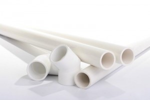 The popularity of polypropylene pipes for creating heating systems is quite high, because they are much cheaper than metal pipes, environmentally friendly and have a good appearance. And the installation of system circuits when using such pipes is greatly facilitated. Special devices for welding pipes, various adapters, fittings, taps and other necessary components have been developed. The installation process itself is similar to assembling the system from the constructor.
System selection
Selection of the type of pipeline
It is necessary to determine the material of the heating pipes:
Steel pipes are practically not used today, because due to their susceptibility to corrosion, their service life is short, installation is laborious, and repairs are difficult.
Experts do not recommend using metal-plastic pipes because of their properties, sometimes bursting at bends under the influence of temperature.
Copper pipes are the most durable and easy to repair, but also the most expensive.
Various types of polymer pipes (for example, made of cross-linked polyethylene or reinforced polypropylene) are often the best choice
If a private house will be heated with plastic pipes, when choosing their brand, it is necessary, first of all, to pay attention to the indicator characterizing the permissible water pressure in the product. To prevent deformation and bending of plastic pipes, very long straight sections should be avoided
It is also necessary to observe during the first start of the heating system for a sharp change in temperature.
To prevent deformation and bending of plastic pipes, very long straight sections should be avoided. It is also necessary to observe during the first start of the heating system for a sharp change in temperature.
Main pipe parameters
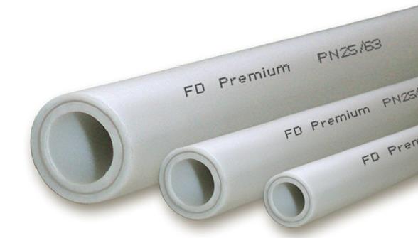
Polypropylene heating pipes of different diameters
For the heating system, pipes are selected not only according to the chemical and physical properties of their material. In the construction of an efficient and economical system, their diameter and length play an important role, since the cross section of the pipes affects the hydrodynamics as a whole. A fairly common mistake is the choice of products of too large a diameter, which leads to a decrease in the pressure in the system below normal, and the heaters stop heating. If the pipe diameter is too small, the heating system starts to make noise.
The main characteristics of the pipes:
- The inner diameter is the main parameter of any pipe. It determines its throughput.
- The outer diameter must also be taken into account when designing the system.
- Nominal diameter is a rounded value, which is expressed in inches.
When choosing pipes for heating a country house, it must be borne in mind that for products made of different materials, different measurement systems are used. Almost all cast iron and steel pipes are marked according to the internal section. Products made of copper and plastic - by outer diameter
This is especially important if the system is to be assembled from a combination of materials.

An example of matching pipe diameters from different materials
When combining different materials in the system, in order to accurately select the pipe diameter, you need to use the diameter correspondence table. It can be found on the Internet. Often the diameter is measured in fractions or inches. One inch corresponds to 25.4 mm.
2. Characterization of the mixture
Since in the condition
tasks are not subject to change
temperature, we accept the flow as isothermal,
those. maintaining a temperature of 30°C for
all over. The composition of the benzene mixture
and toluene allows you to determine the density
and the viscosity of the mixture.
Density at 30 C:
benzene ρb
= 868.5 kg/m3
and toluene density ρT
= 856.5 kg/m3,
then the density of the mixture: ρcm
= 0.7*ρb
+ 0.3* ρT
= 0.7*868.5 + 0.3*856.5 = 864.9 kg/m3
.
Viscosity at 30 C:
benzene μb
= 5,6*10-4
Pa*s and viscosity of toluene μT
= 5,22*10-4
Pa * s, then the viscosity of the mixture: lg
μcm
= 0.7*log
μb
+ 0.3*log
μT
= 0.7*log
(5,6*10-4)
+ 0.3*log
(5,22*10-4)
= - 3.261, and μcm
= 5,48*10-4
Pa*s .
Calculation of hydraulically short pipelines
First case:
Fluid outflow
below the level.

Rice. 43 Calculation scheme
short pipeline (case one)
liquid overflows
from A v V.
Pipe length
,
diameter ,
,
level difference .
.
Movement is steady.
Neglecting
high-speed
pressure
and
 ,
,
Bernoulli's equation is:

(126)
head loss
 - pipe entrance, tap, two turns, tap
and exit from the pipe:
 (127)
(127)
 ;
;
 (128)
(128)
Denote
 is the system resistance coefficient.
Because
 ,
,
then
 (129)
(129)
 (130)
(130)

(131)
Denote:
 ,
,
then
 , (132)
where
 —
—
system flow rate;
 - living area
flow section, m2.
Second case:
Fluid outflow
in atmosphere.
Rice. 44 Calculation scheme
short pipeline (case two)
From the equation
Bernoulli for sections 1 - 1
and 2 - 2, we get
 (133)
(133)
where
 (134)
(134)
Substituting, we have
 (135)
(135)
Denote
 ,
,
then
 (136)
(136)
and
 (137)
(137)
Fluid consumption:

(138)
or
 (139)
(139)
where
 is the flow rate of the system.
Example. Define
kerosene consumption T-1
at a temperature
 ,
,
flowing through the pipeline from welded
stainless steel pipes in paragraphs 1
and 2 (Fig. 45), if
pressure H
in the tank is constant and equal to 7.2
m.
Length of individual parts of the pipeline
 ,
,
diameters:
 ,
,
 .
.
Local pressure losses in the calculations are not
consider.
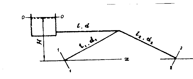
Rice. 45. Scheme
pipelines with parallel branches
So
how pipes 1 and 2 are parallel,
then the lost pressure in these pipes

or
 (140)
(140)
By
the condition of the problem, the dimensions of parallel
pipes made of the same material,
are the same (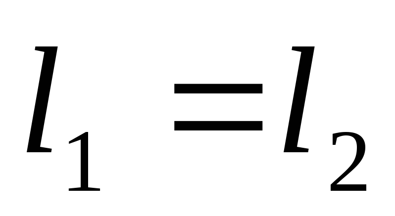 ,
,
 )
)
That's why
 and
and

Hence,
 ;
;
 (141)
(141)
where
 -consumption
in the pipeline;
 ,
, - flow in parallel branches of the pipeline.
The equation
Bernoulli for sections 0
— 0
and 1 - 1
(see fig. 45)

So
how
 ,
, ,
, ,
, ,
,
then

or
 (142)
(142)
The equation
(142) can only be solved by graphical analysis
way. Set to different values
fluid flow in the pipeline and for
these values
 calculate
 and
and
 :
:
 ;
;
(143)
 .
.
By
known quantities
 and
and
 ,
,
 and
and
 determine
Reynolds numbers
 and
and
 ,
,
(144)
For
kerosene T
— 1
 ,
,
 .
.
At
welded stainless steel pipes
equivalent roughness
 ,
,
so the relative equivalent
pipe roughness
 ;
;
 .
.
By
known quantities

and
 ,
,

and
according to the Colebrook plot, we determine
friction drag coefficients

and
and further by equation (142) we set
the necessary pressure. We reduce the calculation to
table
5.
table
5
-
Payment
hydraulic characteristics
pipelines ,
,

2 5 8 ,
1,02 2,55 4,09 
2,04 5,10 8,18 0,032 0,026 0,0245 ,0,053 0,332 0,851 ,
0,312 1,54 3,83 ,
0,795 1,99 3,19 
1,27 3,18, 5,10 0,032 0,0285 0,028 ,0,0322 0,202 0,519 ,
0,23 1,33 3,34 ,0,574 3,07 7,69
 ,
,
 ,
,


 ,
,
 ,
,
 ,
,


 ,
,
 ,
,
 ,
,
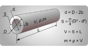
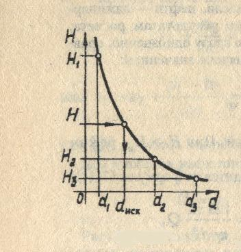
5. Selection of standard pipeline diameter
Industry releases
standardized range of pipes, among
which it is necessary to select pipes with
diameter closest to the calculated
(clause 3.4.). Pipes are designated dn
x δ, where dn
- outer diameter of the pipe, mm; δ - thickness
pipe walls, mm. At the same time, the internal
pipe diameter dext
=dn
– 2* δ.
Guest sizes
pipes according to GOST 8732-78 are the following
row, mm: 14x2; 18x2; 25x2; 32x2.5; 38x2.5; 45x3; 57x3;
76x3.5; 89x4.5; 108x4.5; 133x4; 159x4.5; 219x6; 272x7; 325x8;
377x10; 426x11; 465x13.
According to paragraph 3.4.
internal pipe size 32 mm, then
outer dimension dn
\u003d 32 + 2 * 2.5 \u003d 37 mm. closest in size
pipe 38x2.5 mm. Hosted domestic
diameter 33mm, so equivalent
let's take the diameter duh
= 0.033 m.
The procedure for calculating the cross section of heat supply lines
Before calculating the diameter of a heating pipe, it is necessary to determine their basic geometric parameters. To do this, you need to know the main characteristics of highways. These include not only performance, but also dimensions.
Each manufacturer indicates the value of the pipe section - diameter. But in fact, it depends on the wall thickness and the material of manufacture. Before purchasing a specific model of pipelines, you need to know the following features of the designation of geometric dimensions:
- The calculation of the diameter of polypropylene pipes for heating is done taking into account the fact that manufacturers indicate the outer dimensions. To calculate the useful section, it is necessary to subtract two wall thicknesses;
- For steel and copper pipes, internal dimensions are given.
Knowing these features, you can calculate the diameter of the heating manifold, pipes and other components for installation.
When choosing polymer heating pipes, it is necessary to clarify the presence of a reinforcing layer in the design. Without it, when exposed to hot water, the line will not have the proper rigidity.
Determination of the thermal power of the system
How to choose the right pipe diameter for heating and should it be done without calculated data? For a small heating system, complex calculations can be dispensed with
It is only important to know the following rules:
- The optimal diameter of pipes with natural heating circulation should be from 30 to 40 mm;
- For a closed system with forced movement of the coolant, smaller pipes should be used to create optimal pressure and water flow rate.
For an accurate calculation, it is recommended to use a program for calculating the diameter of heating pipes. If they are not, you can use approximate calculations. First you need to find the thermal power of the system. To do this, you need to use the following formula:
Where Q is the calculated heat output of heating, kW / h, V is the volume of the room (house), m³, Δt is the difference between the temperatures in the street and in the room, ° С, K is the calculated heat loss coefficient of the house, 860 is the value for converting the received values into an acceptable kWh format.
The greatest difficulty in the preliminary calculation of the diameter of plastic pipes for heating is caused by the correction factor K. It depends on the thermal insulation of the house. It is best taken from the table data.
The degree of thermal insulation of the building
High-quality insulation of the house, modern windows and doors installed
As an example of calculating the diameters of polypropylene pipes for heating, you can calculate the required heat output of a room with a total volume of 47 m³. In this case, the temperature outside will be -23°С, and indoors - +20°С. Accordingly, the difference Δt will be 43°C. We take the correction factor equal to 1.1. Then the required thermal power will be.
The next step in choosing the diameter of the pipe for heating is to determine the optimal speed of the coolant.
The presented calculations do not take into account the correction for the roughness of the inner surface of the highways.
Water velocity in pipes
Table for calculating the diameter of the heating pipe
The optimal pressure of the coolant in the mains is necessary for the uniform distribution of thermal energy over radiators and batteries. For the correct selection of the diameters of the heating pipes, the optimal values \u200b\u200bof the speed of water advancement in pipelines should be taken.
It is worth remembering that if the intensity of movement of the coolant in the system is exceeded, extraneous noise may occur. Therefore, this value should be between 0.36 and 0.7 m/s. If the parameter is less, additional heat losses will inevitably occur. If it is exceeded, noise will appear in pipelines and radiators.
For the final calculation of the diameter of the heating pipe, use the data from the table below.
Substituting into the formula for calculating the diameter of the heating pipe in the previously obtained values, it can be determined that the optimal pipe diameter for a particular room will be 12 mm. This is just an approximate calculation. In practice, experts recommend adding 10-15% to the obtained values. This is because the formula for calculating the diameter of the heating pipe may change due to the addition of new components to the system. For an accurate calculation, you will need a special program for calculating the diameter of heating pipes. Similar software systems can be downloaded in a demo version with limited calculation capabilities.
Hydraulic calculation of a simple composite pipeline


 ,
,
 ,
,

Calculations
simple pipelines are reduced to three
typical tasks: determination of pressure
(or pressure), flow and diameter
pipeline. The following is the methodology
solving these problems for a simple
pipeline of constant cross section.
Task
1. Given:
pipeline dimensions
and the roughness of its walls
 ,
,
fluid properties ,
,
liquid flow Q.
Define
required head H (one of the values
components of pressure).
Solution.
The Bernoulli equation is compiled for
flow of a given hydraulic system. Appointed
control sections. Plane is selected
reference Z(0.0),
the initial conditions are analyzed.
The Bernoulli equation is written with
taking into account the initial conditions. From the equation
Bernoulli, we get the calculation formula
type ٭.
The equation is solved with respect to H.
The Reynolds number Re is determined
and the driving mode is set.
The value is found
 depending on the driving mode.
H and the desired value are calculated.
Task
2. Given:
pipeline dimensions
and ,roughness
its walls ,
,
fluid properties ,
,
head H. Determine the flow Q.
Solution.
The Bernoulli equation is written with
taking into account the previous recommendations.
The equation is solved with respect to the desired
Q. The resulting formula contains
unknown coefficient
 , depending
from Re. Direct location under the conditions of this task, it is difficult,
since for unknown Q
cannot be pre-set Re.
Therefore, further solution of the problem
performed by the method of successive
approximations.
- approximation:
Re
→ ∞
 ,
,
determine

2nd approximation:
 ,
,
find λII(ReII,Δuh)
and define

Located
relative error
 .
.
If ,
,
then the solution ends (for training
tasks ).
).
Otherwise, the solution
in the third approximation.
Task
3. Given:
pipeline dimensions (except diameter
d)
the roughness of its walls
 ,
,
fluid properties ,
,
head H, flow Q. Determine the diameter
pipeline.
Solution.
When solving this problem,
difficulty with direct
value definition
 ,
,
similar to the problem of the second type.
Therefore, the decision is appropriate
be carried out using a graphical method.
Multiple diameter values are set .For everybody
 the corresponding value is found
head H at a given flow rate Q (n times
problem of the first type is resolved). By
the calculation results are plotted .
.
The desired diameter is determined from the graph
d corresponding to the given value
pressure N.
6. Refinement of fluid velocity
We express from the equation
(20) fluid speed:
w = 4*
Vc/(π*
duh2)
= 4*1,61*10-3/(3,14*(0,033)2)
= 1.883 m/s.
3.7. Definition
fluid motion mode
Fluid movement mode
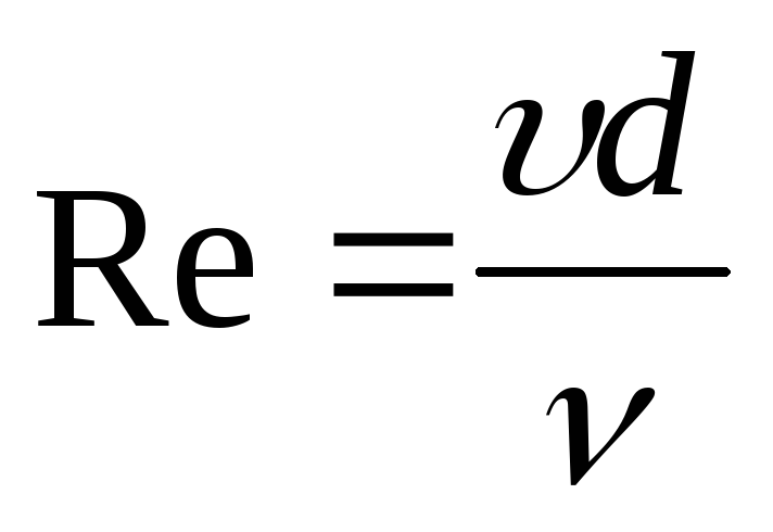
determine by the Reynolds equation
(formula (3)):
Re
=W*
duh
*pcm
/μcm
= 1,883*0,033*864,9/5,48*10-4
= 98073.
Driving mode advanced
turbulent.
3.8. Definition
coefficient of hydraulic resistance
Let's take the average value
roughness l
= 0.2 mm, then the relative roughness
will be ε = l/
duh
= 0,2/33 = 6,06*10-3.
Let us check the condition Re
≥ 220*ε -1.125.
220*(6,06*10-3)-1,125
= 68729, i.e. less than Re
= 98073. The area of motion is self-similar and
hydraulic resistance coefficient
is found by formula (14):
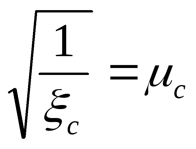
1/
λ0.5
= 2*lg(3,7/ε)
= 2*lg(3.7/6.06*10-3)
= -6.429. Whence λ = 0.0242.
3.9. Finding
local resistance coefficients
According to paragraph 3.2. and
given that the coefficients
local resistances are as follows:
is the entrance to the pipe ξtr
= 0,5;
—
normal valve ξveins
= 4,7;
—
knee 90
ξcount
= 1,1;
is the exit from the pipe ξtuesday
= 1;
—
measuring aperture (at m
= (duh/D)2
= 0.3, then ξd
= 18,2)
∑ξms
= ξtr
+ 3* ξveins
+ 3* ξcount
+ ξd
+ ξtuesday
= 0,5 + 3*4,7 + 3*1,1 + 18,2 + 1 = 37,1.
Geometric
lifting height of the mixture is 14 m.
3.10. Definition
total pressure loss in the pipeline
Sum of all leg lengths
pipeline 31 m, R1
= P2.
Then complete
hydraulic resistance of the network
formula (18):
ΔРnetworks
= (1 + λ * I/
duh
+ ∑ξms)*
ρ*W2
/2 + p*g*hgeom
+ (P2
- R1)
= (1 + 0,0242*31/0,033 + 37,1)*864,9*1,8832/2
+ 864.9 * 9.81 * 14 = 168327.4 Pa.
From the relation ΔРnetworks
= ρ*g*h
define hnetworks
= ΔРnetworks/
(ρ*g)
\u003d 168327.4 / (864.9 * 9.81) \u003d 19.84 m.
3.11.
Construction of pipeline characteristics
networks
We will assume that
network characteristic is
a regular parabola starting from a point
with coordinates Vc
= 0; h
on which the point with coordinates is known
Vc
= 5.78 m3/h
and Hnetworks
= 19.84 m. Find the coefficient of the parabola.
General equation of a parabola
y \u003d a * x2
+b.
Substituting the values, we have 19.84 \u003d a * 5.782
+ 14. Then a = 0.1748.
Let's take a few
volumetric performance values
and determine the head hnetworks.
Let's put the data in a table.
Table - Dependency
network pressure from performance
pump
| Performance, m3/h |
Network head, m |
| 1 | 14,17 |
| 2 | 14,70 |
| 3 | 15,57 |
| 4 | 16,80 |
| 5 | 18,37 |
| 5,78 | 19,84 |
| 6 | 20,29 |
| 7 | 22,57 |
| 8 | 25,19 |
| 9 | 28,16 |
| 10 | 31,48 |
By
to the obtained points we build a characteristic
network (line 1 in Figure 2).
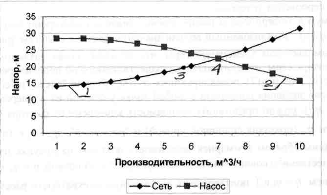
Figure 2 - Combination
network and pump characteristics:
1 - characteristic
networks; 2 - pump characteristic; 3 -
settlement point; 4 - working point.
Heating pipe material
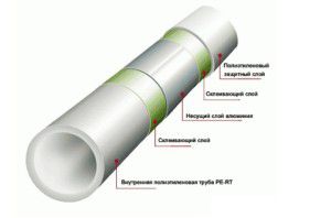
Construction of polymer pipes
In addition to the correct choice of pipe diameters for heat supply, you need to know the characteristics of their material of manufacture. This will affect the heat loss of the system, as well as the complexity of installation.
It should be remembered that the calculation of the diameters of heating pipes is performed only after choosing the material for their manufacture. Currently, several types of pipelines are used to complete heat supply systems:
- Polymer.They are made of polypropylene or cross-linked polyethylene. The difference lies in the additional components added during the production process. After calculating the diameter of polypropylene pipes for heat supply, you need to choose the right thickness of their wall. It varies from 1.8 to 3 mm, depending on the parameters of the maximum pressure in the lines;
- Steel. Until recently, this was the most common option for arranging heating. Despite their more than good strength characteristics, steel pipes have a number of significant drawbacks - complex installation, gradual surface rusting and increased roughness. Alternatively, pipes made of stainless steel can be used. One of their cost is an order of magnitude higher than the "black" ones;
- Copper. According to the technical and operational characteristics, copper pipelines are the best option. They are characterized by sufficient stretch, i.e. if water freezes in them, the pipe will expand for some time without loss of tightness. The disadvantage is the high cost.
In addition to the correctly selected and calculated diameter of the pipes, it is necessary to determine the method of their connection. It also depends on the material of manufacture. For polymers, a coupling connection is used by welding or on an adhesive basis (very rarely). Steel pipelines are mounted using arc welding (better quality connections) or threaded method.
In the video you can see an example of calculating the diameter of pipes depending on the optimal flow rate of the coolant: