Features of water meter units
It is difficult to imagine a well-maintained facility without a connected sewerage and water supply system. At the same time, both the water supply system and the sewerage system can be both autonomous and centralized. In order to connect them to external highways today, specialists use special water measuring units
. Thanks to them, it becomes possible to accurately and quickly determine how much water was spent. Thus, the advantage of using water metering units is obvious, and if there are doubts whether they need to be installed, or whether they are intended only for installation in industrial facilities, it will be useful to learn about their versatility of use. True, depending on the type of object, the type of water measuring unit also depends. The water-measuring units themselves are simple and with a bypass line.
In addition to the above classification, there is also a category of their division into types. So, vane models are suitable for installation at facilities where there is no intensive and constant water flow, but there is still a need to record such indicators. Turbine options are more designed for objects with an industrial scale of water consumption. But the combined options combine the characteristics of vane and turbine types, and they are most suitable for use at facilities with an intermittent need for water consumption.
The coherence of its work with the entire system and the accuracy of its readings as a whole will largely depend on the correct choice of the water meter unit, as well as the accuracy during its installation.
), pipeline fittings (gate valves or gates), a drain cock, a technical pressure gauge, connecting parts (elbows, transitions, tees) and branch pipes from steel water pipes.
There are water meter nodes:
Simple (no bypass line);
With bypass line (with bypass).
Bypass line at the cold water meter
required if there is one entrance to the building, as well as in cases where the water meter does not provide for the estimated water flow for internal fire extinguishing. The bypass line is calculated for the maximum (including fire) water flow. On the bypass line, it is necessary to provide for the installation of a gate valve or a butterfly valve, usually with an electric drive, sealed at normal times in the closed position.
If the meters are not designed for the maximum water flow for fire fighting, on the bypass line it is necessary to provide for the installation of a gate valve (gate) with an electric drive
, which will open automatically simultaneously with the start of fire pumps from buttons installed at fire hydrants or other automatic devices.
Pipe fittings
installed before and after the water meter for the possibility of replacing it or verifying the correctness of its readings, as well as disconnecting the internal water supply network from input and emptying it. The control and drain valve (or a pipe with a plug) is used to drain water from the internal water supply network, control pressure (available pressure), verify the correctness of the water meter readings and detect water leaks in the system.
The water meter unit consists of a device for measuring the amount of water consumed, shutoff valves, a control and release valve, connecting parts and branch pipes made of water and gas steel pipes.
There are simple water meter units and water meter units with a bypass line. A water meter assembly with a bypass line is used if there is one input. It is also applicable if the device for measuring the amount of water consumed is not designed to pass the fire flow.Shut-off valves are installed before and after the measuring device in order to be able to replace it or check the correctness of its readings, as well as disconnecting the internal network from the input and emptying it.
The main error codes in Delonghi coffee machines
|
Error |
What does |
Recommendations |
|
FILL TANK Fill the tank |
The water tank is empty or not properly inserted. The tank is dirty or covered with scale. |
Fill the water tank and insert as far as it will go. Rinse the tank or descale. |
|
GROUND TOO FINE / ADJUST MILLAND Grinding too fine, adjust the grind and install the water spout, then press "OK" |
Coffee from the draft group flows out slowly. The coffee machine does not make coffee. |
Turn the grinding knob counterclockwise towards the number 7 (when the coffee grinder is running). Install the hot water supply unit, press the "BOILING WATER" button and drain water through it for several seconds until it turns off. If it does not help, contact the service center. |
|
EMPTY GROUNDS CONTAINER Empty the grounds cassette |
The coffee grounds container is full or not installed. |
Empty the grounds container and reinsert. |
|
INSERT GROUNDS CONTAINER Insert the grounds cassette |
After cleaning, the grounds container is not inserted. |
Open the service door and reinsert the grounds container. |
|
ADD PRE-GROUND COFFEE Pour ground coffee |
When the mode is selected, the ground coffee is not poured into the funnel. |
Pour 1-2 scoops of ground coffee into the funnel. |
|
FILL BEANS CONTAINER Fill the bean container |
Run out of coffee beans. If the grinder is very noisy, it means that a small object with beans is blocking it. |
Fill the bean container. Contact the service center. |
|
DESCALE Descaling |
Indicates that scale has formed in the coffee machine. |
Run the descaling program as soon as possible. |
|
PRESS/SET Press "SET" |
The brewing unit may not be inserted into the coffee machine after cleaning. |
Leave the service door closed and do not insert the brewing unit into the coffee machine and follow the instructions that appear on the coffee machine's display. |
|
CLOSE DOOR close the door |
The service door is open. |
If you cannot close the door, make sure the brewing unit is correctly inserted. If it does not help, contact the CoffeeService service center. |
|
INSERT WATER SPOUT Insert water spout |
The faucet button is pressed and the water supply unit is not inserted. |
Insert the hot water spout. |
|
INSERT INFUSER ASSEMBLY Insert the brewing unit |
The brewing unit may not be inserted into the coffee maker after cleaning. |
Insert the brewing unit as far as it will go. |
|
LESS COFFEE Reducing the dose of coffee |
The ground coffee funnel is clogged. Too much coffee bean or ground coffee has been used. |
Empty the funnel with a long thin object (not sharp). Select a less strong coffee or reduce the amount of ground coffee and then turn the coffee brewing on again |
|
GENERIC ALARM General alarm |
The coffee machine inside is very dirty. |
Thoroughly clean the inside of the coffee machine. If the coffee machine continues to display the message after cleaning, contact the CoffeeService service center. |
Only a qualified repairman will be able to correctly decode the error code of the Delonghi coffee machine. If you need qualified assistance in debugging or repairing your coffee machine, please contact CoffeeService — 8 (495) 705-99-44 every day from 7:00 to 23:00.
General provisions
- The procedure regulates the rules for installing cold water metering devices in residential and other premises.
- Devices are installed, as a rule, at the inputs to the residential premises after the shutoff valves. In other cases, coordination with CJSC Vodokanal is required.
- Installation of devices and metering units is carried out at the inputs to the Subscriber's premises, on pipelines of cold water supply systems at his expense.
- To account for the volume of water supply services, metering devices that meet technical requirements are used.Metering devices must have passports, certificates and, during the entire period of operation, comply with the technical conditions for them. Passports during the entire period of operation are kept by the Subscriber (a photocopy of the passport is provided to the subscriber department of CJSC Vodokanal). The device to be installed must be included in the "State Register of Measuring Instruments of the Russian Federation", have certificates of conformity and a stamp of state verification. The corresponding sign must be in the technical passport for the device.
- The installation of water meters is carried out under an agreement between a specialized organization and the Client in full compliance with the requirements of the technical specifications for the installation of a meter and the installation project. Payment for the cost of works and services is made by the Client in accordance with the concluded agreement between him and the specialized organization and the estimate.
3. Symbol of the pipeline and its numbering.
Conditional
pipeline designation consists of
conditional graphic designation (in
line) and alphanumeric
designation characterizing the purpose
and the type of fluid being transported.
Alphanumeric designations
sanitary pipelines
systems (external water supply networks
and sewerage, heat supply, internal
plumbing and sewerage, hot
water supply, heating, ventilation
and conditioning).
Risers
systems are marked with the brand “‘St” with
adding system designation and
serial number of the riser within
systems. For example, St B1-1, means,
that the drawing shows a riser (St)
household and drinking water supply
(B1), the first in this building (1). And so on
the task came out 6 risers: St B1-1, St B1-2,
St B1-3, St B1-4, St B1-5, St B1-6.
Trunk
pipelines
(distribution network) connect the water meter
node (increasing installation) with
vertical risers.
They serve to distribute water between
these stands.
Risers
(distribution pipelines)
are vertical sections.
internal plumbing, through which
water rises to the appropriate
height (floor).
TO
water fittings
(sanitary appliances) include various
taps, faucets for bathtubs, washbasins,
sinks, float valves for flushing
toilet cisterns.
fittings
varies depending on the destination:
shut-off, adjustable, water folding,
safety.
Installation and installation of a water meter unit
The installation of a water meter unit is carried out exclusively on existing water pipes, which must be filled with water. Moreover, the system must be flushed and pressure tested. The node is installed at the outer wall of the building in a place where you can easily approach if you need to check the meter readings. The room should have natural lighting, and the air temperature should not be below +5 degrees. Water metering units are most often located in basements or on stairwells.
The device is attached to the floor or walls, its axis must be at a height of 0.3-1 m from the floor itself. Today, vane and turbine meters, which are part of water metering units, are very popular. The first type of meters is mounted on horizontal sections of pipelines with a threaded connection.
Turbine devices for measuring water consumption are connected to pipelines on flanges. Water in these pipes moves from bottom to top. They differ from vane ones in that here the axis of rotation is parallel to the direction in which the water flows. Counters need regular checks on the accuracy of their results. Such an inspection can be organized by specialists responsible for the installation and maintenance of the water meter assembly.Devices that control the consumption of hot and cold water must be reliably protected from self-disassembly in order to change the meter readings. Especially for this, devices are sealed by those organizations that have the appropriate license.
The water meter assembly consists of the following elements:
gate valves (Hawle, M3B, AVK, Belgicast);
coupling, brass or flanged filter;
water meter;
check valve, which can be coupling and wafer;
VChShG shaped parts (pipe, elbow, transitions, branch).
The installation of the water meter unit is always carried out on a running system. The nodes are mounted in dry rooms that are not residential. The device itself is installed on a straight section, and the nodes are assembled from a small number of shaped parts, bends, etc. This is done in order to avoid unnecessary pressure losses.
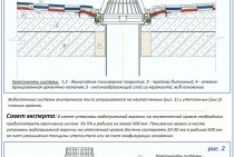
The standard scheme of the water metering unit of an apartment building:
As the presented diagram shows, the water meter assembly includes a main line and a bypass line. In the main line, everything is quite simple: an inlet gate, a water meter, a special filter, a check valve and an outlet gate are installed here. The bypass line also contains a gate. As for the main line valves, they are completely open in the working position, and the bypass line valve is closed.
What is the bypass line for? The presence of this line is determined by the existing requirements of the Ministry of Emergency Situations, which provide for the provision of optimal water supply in the event of an unforeseen situation, for example, a fire. It is also necessary to ensure a regular water supply to the house, even during planned or spontaneous repairs. Thus, water enters the house, regardless of how long the repair takes, the replacement of the water meter (if it is checked) or the cleaning of the filter. Under such circumstances, the bypass line gate opens, and opens completely to the stop, and then the main line gates (inlet and outlet gates) are closed.
Next, pressure is released from the main line, which becomes possible due to the presence of a two - or three-way valve. This valve is installed between the check valve and the outlet gate. After all the necessary preparations, the work is carried out directly. When all work has been completed, the main channel gates must be fully opened, and the bypass line gate must be completely closed.
At the same time, it should be noted that the bypass line located in the water metering unit imposes special requirements on the tightness of the gates in the closed position. Also, similar requirements can be presented in the case of repair work during the maintenance of the water meter unit.