1. Determination of the required value of heat transfer resistance Rtr for g. Moscow
4.1.1. Buildingresidential, therapeutic—preventiveandchildren's
institutions, schools, boarding schools
Initialdata
Heating period temperaturetfrom.nep.= -3,1С°
(average temperature of the period with the average daily temperature below or
equal to -8С ° according to SNiP 23-01-99, tab. one)
Duration from periodZfrom.nep.= 214 days
(length of the period with an average daily temperature below or
equal to -8С ° according to SNiP 23-01-99, tab. one)
Estimated winter outdoor temperaturetH= -28C°
(average temperature of the coldest 5-day day with a security of 0.92 according to
SNiP 23-01-99, tab. one)
Required resistance to heat transfer from sanitary
and comfortable conditions
= n (tB—tH)/ΔtHαV \u003d 1.379 m2oSWtf-la (1) SNiP II-3-79 *]
whereP= 1
tB= 20C° - calculated temperature of the internal air
tH\u003d -28С - estimated outdoor air temperature
ΔtH\u003d 4C ° - standard temperature difference table. 2* SNiP II-3-79*]
αv\u003d 8.7 Wm2С ° - heat transfer coefficient of the inner surface
enclosing structure Table 4* SNiP II-3-79*]
Required resistance to heat transfer from the conditions of energy saving
(second phase):
PriGOSP=4000 RTp= 2.8 m2°SW
PriGOSP=6000 RTp= 2.8 m2°SW
GPSO= (tB—tfrom.per.)Zfrom.per.= 4943 f-la (1a) SNiP II-3-79*]
RTp(2)=3.5-(3.5-2.8)(6000-4943)/(6000-4000)=3.13
m2°С\Wtabl. 1b* SNiP II-3-79*]
= 1,379= 3,13
TOcalculationaccept= 3.13 m2OWITHTue
Taking into account the coefficient of thermal engineering uniformityr = 0.99 for the system
external thermal insulation, reduced resistance to heat transfer
Ro = r= 3.13/0.99=3.16 m2°SW
4.1.2. Buildingpublic, Besidesspecified
above, administrativeandhousehold, per
exceptionpremisesWithwetandwet
regime
InitialdataThe same
Required resistance to heat transfer from sanitary and hygienic
comfortable conditions
= n (tB—tH)/ΔtHαV = 1.175m2°SWtf-la (1)
SNiP II-3-79*]
whereP= 1
tB= 18С° — design temperature of the internal air
tH\u003d -28С - estimated outdoor air temperature
ΔtH\u003d 4C ° - standard temperature difference table. 2* SNiP II-3-79*]
av\u003d 8.7 Wm2С ° - heat transfer coefficient of the inner surface
enclosing structure tab. 4* SNiP II-3-79*]
Required resistance to heat transfer from the conditions of energy saving
(second phase):
PriGOSP=4000 RTp= 2.4 m2°SW
PriGOSP=6000 RTp= 3 m2oSW
GPSO= (tB—tfrom.per.)Zfrom.per.= 4515
Rtr(2) \u003d 3 - (3 - 2.4) (6000 - 4515) / (6000 - 4000) \u003d 2.55 m2 ° C \ Wttabl. 1b* SNiP II-3-79*]
= 1.175Rneg(2) = 2,55
TOcalculationaccept= 2.55 m2OWITHTue
Taking into account the coefficient of thermal engineering uniformityr = 0.99 for the system
external thermal insulation, reduced resistance to heat transfer
Ro = r= 2.55/0.99=2,58m2°SW * for other regions, the GSOP calculation is similar
Temperature, relativehumidityand
temperaturepointsdewinternalair
premises, acceptedatheat engineeringcalculations
enclosingstructures (adj. LSP 23-101-2000 "Designthermalprotectionbuildings")
|
Building |
Temperature |
Relative |
Temperature |
|
Residential, educational institutions |
20 |
55 |
10,7 |
|
Polyclinics and medical |
21 |
55 |
11,6 |
|
Preschool |
22 |
55 |
12,6 |
|
Buildings public, administrative and domestic, with the exception of premises with damp wet conditions |
18 |
55 |
8,8 |
Requiredresistanceheat transferRTp ((m2°C)/Tue) for
somecities, calculatedfromconditionsenergy saving
(secondstage)
|
Town |
Moscow |
Saint Petersburg |
Sochi |
Khanty-Mansiysk |
Krasnoyarsk |
|
Residential buildings, medical and preventive care institutions, schools, boarding schools |
3,13 |
3,08 |
1,74 |
3,92 |
3,62 |
|
Buildings public, administrative and domestic, with the exception of premises with damp wet conditions |
2,55 |
2,51 |
1,13 |
3,21 |
2,96 |
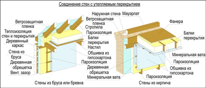
Connecting walls with insulated floors
If there is an attic in the building above the ceiling that is not used, it is necessary to carefully connect the insulation and the vapor barrier film at the junction of the ceiling and the wall.
A good option would be the presence in the normal state of a wooden beam ceiling or its load-bearing elements.Wooden beams have excellent thermal insulation qualities and, therefore, heat loss when the beam passes through the wall insulation will be negligible. It is possible that it will be necessary to repair it, strengthen the elements and restore the missing parts. But the vapor barrier film that protects the insulation (for example, mineral wool) above the floor beams or between them must be connected to the vapor barrier film of the false wall as tightly as possible.
Brick arched ceilings or Klein ceilings are practically not used at present, and have been preserved only in old buildings. Such an overlap is quite difficult to insulate due to the use of steel two-tee beams in its supporting structure. The brick of such a ceiling above the internal partition of the building can be chipped off in order to be able to connect the insulation of the ceiling and the wall. But on the metal beams of the ceiling, due to contact with cold air, condensation will form. In such areas, insulation and plaster will be constantly wet. Alternatively, you can chop off part of the wall around the beams (perhaps even through) and insulate these places with polyurethane foam. The layer of such thermal insulation should be even and about 40-50 mm thick. And to achieve this is problematic.
There is another option, though expensive, but effective. It lies in the fact that the steel floor beams rest on a special structure of racks and beams inside the room (it turns out, as it were, a “box in a box”). At the same time, the ends of the floor beams resting on the outer wall are cut off, and the floor along the perimeter of the wall is disassembled. The internal steel structure and the ceiling are insulated with mineral wool. As a result, cold bridges are eliminated. You may need to make a reinforcing crown along the top of the wall. The disadvantage of this method is the presence of a structure inside the building, the elements of which may not fit into the interior of the room.
Difficulties may also arise when connecting the insulated walls with the Ackerman floor.
The design of such an overlap includes a crown of reinforced concrete. Such a crown can only be insulated from the outside of the wall. But for buildings of historical and architectural value, dismantling and subsequent restoration of facade elements is a rather expensive procedure. For thermal insulation of floors with a crown, the use of special insulated friezes, cornices or expanded polystyrene rust is suitable. In order for the thermal insulation to be sufficiently effective, it is necessary to insulate the outer wall under the crown in a width of about 30-50 cm. The thermal insulation material on the inside of the wall must fit snugly against it without a gap.
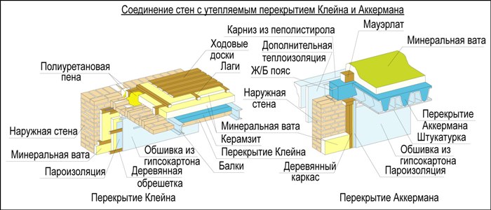
It is best to make the ceiling often ribbed with wooden beams. The beams are laid in increments of 30-60 cm. The floor structure is sheathed with OSB-plate or sheets of moisture-resistant plywood. With this design, any slightest cold bridges are completely excluded, therefore, heat leakage is minimized. However, such a constructive solution for wall insulation leads to the fact that inside the old "shell" of the building with its own history, a modern house is built according to Canadian technology.
But the appearance of the building is preserved, which is especially important for architectural and historical monuments.
New materials:
- Garage doors - which ones to choose
- Terrace tiles are practical and reliable
- Terrace with wooden deck
- Terrace inverted flooring device
- How to build a garage
Previous materials:
- How to make an attic floor
- Calculation of insolation of residential premises
- Placing a bath on the site - tips
- Benefits of a log home
- Modern foundation for a private house
Next page >>
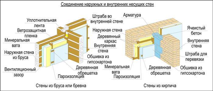
Connection of external and internal load-bearing walls
Internal wooden walls made of logs or timber usually do not need additional thermal insulation at the junction areas.But the provision of thermal insulation of the outer walls at the junctions with the cylindrical beam of the inner walls is necessary. It is not recommended to use polyurethane foam for insulation of such joints (due to its fragility). The best option would be to use a special sealing polyurethane foam tape. Polyurethane foam has good thermal insulation properties, does not allow moisture to pass through, is an elastic and fairly durable material. For the convenience of insulation work, it is possible to make not very deep furrows in the wall, on both sides, leveling the irregularities of logs or timber.
The connection of external insulated walls with internal load-bearing walls made of brick or stone is a more laborious process. This is due to the heat-conducting properties of stone and brick, due to which significant cold bridges are formed. The most successful option for this connection would be to replace part of the inner wall, from floor to ceiling, at the site of its docking with the outer wall of the building, with blocks of cellular aerated concrete or porous ceramics. Thanks to the use of such blocks, possible cold bridges are eliminated. To increase the strength of the resulting insert, the old and new walls are tied up with a strap and fastened with reinforced rods between the blocks (in each row or through a row).
Slope insulation units
Node 45. Node for finishing an insulated vertical side slope without a quarter. Node B. Adjacents of the insulation system to window blocks. Option 1, 2. Knot B. Adjacencies of the insulation system to window blocks. Option 3Knot 46. Knot for finishing the insulated vertical side slope with a quarter. Knot G. Adjacency of the insulation system to window blocks. Option 1, 2. Knot G. Adjacencies of the insulation system to window blocks. Option 3Knot 47. Knot for finishing an insulated vertical slope without a quarter. Knot D. Adjacents of an insulated surface to window blocks. Option 1, 2. Node 48. Node for finishing a non-insulated vertical slope with a quarter. Node E. Connections of the insulation system to window blocks. Option 1, 2. Node 49. Node for finishing the insulated upper slope without a quarter. Node 50. Node for finishing the insulated upper slope with a quarter. opening with a roller shutterNode 54. Node adjoining the system to a window block without a slope. Node G. Surface adjoining to window blocks. Option 1, 2. Knot 55. Knot of lower slope insulation when installing a window sill to the reinforced layer. Section 1-1 with side slope insulation. Section 1a-1a without side slope insulation. Knot 56. Knot of lower slope insulation when installing a window sill after the installation of a reinforced layer. Option 1. Sloping slab up to 30 mm thick. Cut 2-2 with side slope insulation. Option 2. Sloping slab with a thickness of more than 30 mm. Section 3-3 with side slope insulation. Section 3a-3a with an insulated side slope. Node 58. An insulated lower slope assembly when installing a window sill after the reinforced layer. Section 4 - 4. With side slope insulation. Section 4a - 4a. With insulated side slope. Knot 59. Knot of the insulated lower slope when installing a window sill to the reinforced layer. Section 5 -5. With side slope insulation. Section 5a-5a. No side slope insulation. Knot 60. Knot for insulation of the lower slopes of glazed balconies and loggias. Section 6-6. With side slope insulation. Section 6a-6a. Without insulation of the side slope. Node 61. Node for insulating the upper inclined slope. Node 62. Node for finishing the upper inclined slope without insulation. Node 63. Node for insulating the inclined side slope. Node 64. Node for finishing the inclined side slope without insulation. Node 65. Node for insulation sloping slope with a ledge. Node 66. Finishing unit of an inclined slope with a ledge without insulation.
The object is an administrative building with reinforced concrete walls, Moscow
1. General Provisions
Humidity
room mode - normal, humidity zone for Moscow - normal,
therefore, the operating conditions of enclosing structures - B
V
in accordance with the recommendations of SNiP II-3-79* and MGSN
2.01-99 (clause 3.4.2. and clause 3.3.6) reduced resistance to heat transfer (Ro) for exterior walls
should be calculated without taking into account the filling of light openings with checking the condition that
temperature of the inner surface of the enclosing structure in the zone
heat-conducting inclusions (diaphragms, through mortar joints, panel joints,
ribs and flexible connections in multilayer panels, etc.), in corners and window slopes
must not be lower than the dew point temperature of the indoor air. At a temperature
indoor air 18°C and its relative humidity 55% temperature point
dew is 8.83°C.
Required
reduced resistance to heat transfer for Moscow from the condition
energy saving (second stage)
Rtr= 2.55 m2оС/W (clause 2.1* of SNiP II-3-79*)
2. Calculation of the reduced resistance to heat transfer
Design
walls:
1)
reinforced concrete wall
δ1=
0.2 m
λ1=
2.04 W/m2oS
(Appendix 3 SNiP II-3-79*)
2)
The main insulation is polystyrene foam boards PSB-S 25F
δ2=?
λ2
=0.042 W/m2°C (item 7, appendix E SP 23-101-2000 "Design
thermal protection of buildings")
Cuts
from mineral wool boards 150-200mm wide
δmvp
= δ2
λmvp
= 0.046 W/m2oS
3)
External plaster
δ3=
0.006 m
λ3= 0,64
W/ m2oS (app. 3 SNiP
II-3-79*)
Resistance
heat transfer for this wall on site
with basic insulation
Rpsb-s= 1/αv + δ1/λ1 + δ2/λ2 + δ3/λ3+
1/αn
where:
αv= 8.7 W/m2°C
- heat transfer coefficient of the inner surface of the walls (Table 4 SNiP II-3-79 *)
αn = 23 W/m2°C
- heat transfer coefficient of the outer surface of the walls (Table 6 SNiP II-3-79 *)
Required
core insulation thickness
= (Rtr - (1/αv + δ1/λ1 + δ3/λ3+ 1/αn,)) λ2 = 0,096 m
Accept
insulation thickness δ2
= 0.1 m, then the calculated
reduced resistance to heat transfer
Rpsb-s= 1/αv + δ1/λ1 + δ2/λ2 + δ3/λ3+
1/αn = 2.65 m2°C/W
Resistance
heat transfer to plot with
incisions:
Rpsb-s = 1/αv + δ1λ1 + δ2λ2 + δ3λ3 + 1/αn = 2.44 m2°C/W
V
in accordance with the requirements of clause 2.8. SNiP II-3-79*, with
the accepted ratio of insulation 80% PSB-S and 20% mineral wool, given
heat transfer resistance
Ra = 0,8 Rnc6-c + 0,2 Rmbh= 2.61 m2°C/W
With considering
thermal inhomogeneity coefficient r= 0.99 for the external thermal insulation system,
reduced resistance to heat transfer Ro = Ra×r = 2.58 m2°C/W
Ro= 2.58 m2oS/W > RTp= 2.55 m2°C/W
Finally
we accept the thickness of the insulation 0.1 m
3. Temperature detection
the inner surface of the wall in the slope area
V
in accordance with the technical solutions of the units, the insulation around the windows is installed
with an overlap on the opening of 40 mm. Therefore, in the slope zone, we accept the wall structure:
reinforced concrete wall 70 mm, insulation 40 mm, external plaster 6 mm.
Temperature
inner surface τv
= tB — n(tB — tH)/RoαB
where
Ro =1/αv + 0.07/λ1 +
0.04/λprofit center + δ3/λ,3 + 1/αn
= 1.07 m2°C/W
n= 1 (Table 3*)
tB\u003d 18 ° С - temperature
indoor air
tn\u003d -28 ° С - estimated
outdoor temperature
αv= 8.7 W/m2°C
- heat transfer coefficient of the inner surface of the walls (Table 4 * SNiP II-3-79 *)
τv = 13.07 >8.83 °С
Temperature
the inner surface of the wall in the slope area above the dew point temperature.
HEAT ENGINEERING CALCULATION
for the system of external thermal insulation "SINTEKO"
(insulation - mineral wool boards)