Calculation of floor insulation made on the ground
The method of "heat engineering" for floor coverings of the lower floors differs significantly from the calculation of the thermal resistance of other enclosing structures. For the lower thermal barrier, everything is connected with a different environment: contact with air, soil, which traps heat, prevents its transfer, and even absorbs it. Calculation techniques differ due to a large number of third-party factors, however, each requires a separate study.
The calculation of the floor of the lower floors of structures, for example, on a pile foundation, is calculated using the Machinsky method, which involves dividing the floor covering into 4 conditional zones. They are formed along the perimeter of the structure on the floor surface with a width of 200 cm. For a separate zone, there are calculated indicators that show the resistance to heat transfer (measured in square meters K / W):
 Heat Transfer Resistance Zones
- 1 zone - 2.1 m2K / W.
- Zone 2 - 4.3 m2K / W.
- Zone 3 - 8.6 m2K / W.
- 4 zone - 14.2 m2K / W.
In narrow rooms, the last zones are often absent; in spacious rooms, the last zone occupies the place that remains from the first three.
When building a floor in recessed houses with a basement, the height of the wall to the ground line from the street is considered. Foundation concrete is taken as equivalent to soil, the heat that leaves through the soil layer conditionally moves to the surface.
Heat leaving through the floor surface is calculated as penetrating deep into the soil. This means that the degree of saturation with heat and the temperature difference are not the same. Such data are indicated in the Sotnikov calculation method, however, for its correct application, it is necessary to determine the initial indicators for climate.
For the correct implementation of the calculated data indicating the resistance to heat transfer, there is a special program. To get the result, you need to fill in several lines.
Determination of heat losses for heating ventilation air.
Heat loss, Qv,
W, calculated for each
heated room with one
or more windows or balconies
doors in the outer walls, based on
the need for heating
outdoor heating appliances
air in the volume of a single air exchange
per hour according to the formula:
-for
living rooms and kitchens:
 ,
,
Tue (2.7)
where Qv- heat consumption for
heating of the outside air that enters
into the room to compensate for the natural
hood not compensated heated
supply air or for heating
outside air entering
stairwells through opening
in the cold season, external doors
in the absence of air-thermal curtains.
 - square
floor of the room, m2;
 - height
rooms from floor to ceiling, m, but not
more than 3.5.
- for
staircase:
 ,
,
W; (2.8)
where B is the coefficient,
taking into account the number of entrance vestibules.
With one vestibule (two doors)
 = 1,0;
 —
—
building height (stairwell height),
m;
P is the number of people in
building, persons;
Q1 – calculated heat losses,
Tue
Q1=∑Q+Qv, W.
(2.9)
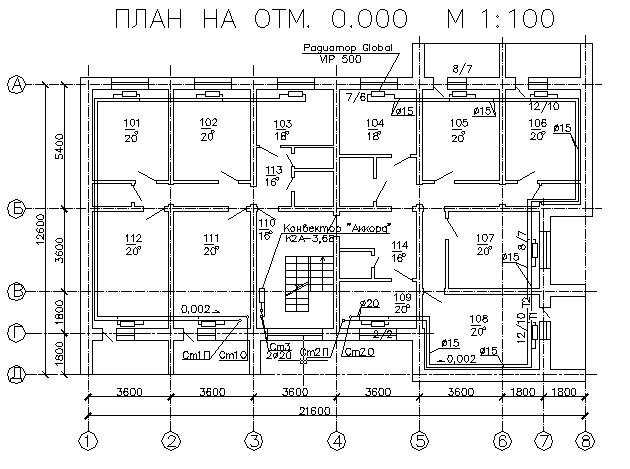
Rice. 2.1. Plan at 0.000.
Table 2.1 Calculation of heat losses and
heat transfer through the enclosing
designs
|
Number premises |
Name |
fencing |
Qv, |
Q1, |
||||||||||
|
tv, |
designation |
orientation |
% w, |
aXb, |
A, |
1/R W/(m2 C) radW/(m2 deg) |
tv— |
n |
1 + |
Qa |
||||
|
1 |
2 |
3 |
4 |
5 |
6 |
7 |
8 |
9 |
10 |
11 |
12 |
13 |
14 |
15 |
|
Σ |
-
Number of the room. Three digit number.
The first digit is the floor number (calculation
we lead for the first, intermediate and
last floors.) Second and third
digit - the serial number of the room on
floor. Numbering is from the left
the upper premises of the building (on the plan)
clockwise for rooms with
exterior walls, then for indoors,
without external walls.
2, 3.Room name and temperature
internal air in it:
LCD - living room -20оС;
KX - kitchen - 18 ° C;
PR - entrance hall - 16оС;
VN - bathroom against the outer wall -
25°C;
UB - latrine - 20оС;
C / U - combined bathroom - 25 ° C;
LK - stairwell - 16оС;
LP - elevator room - 16оС;
The temperature in the rooms is taken
on .
4. Names of the fence:
HC - outer wall;
DO - window, double glazing (TO -
triple glazing);
PL - floor (overlap above the basement),
taken into account for the premises of the first
floors;
PT - ceiling (attic floor),
for the last floor;
DV - external doors to the building on the LC;
BDV - balcony external doors.
-
Orientation - orientation of the outside
enclosing structure on the side
Sveta. (depending on orientation
facade with staircase). -
%/ w- repeatability
%, and wind speed in direction, m/s. -
aхb, m –
dimensions of the corresponding fence
according to the rules of measurement. -
A - the area of \u200b\u200bthe fence:
A=axb,
m2(2.10)
-
1/R– accepted
depending on the name of the fence. -
n is a coefficient that takes into account
location of building envelopes
in relation to outside air.
Accepted according to Table 3. For outdoor
walls, windows, doors n=1. For
ceilings over unheated
basements without skylights n=0.6.
for the attic floor n=0.9. -
Temperature difference between internal and
outside air, or temperature difference
from different sides of the fence, oC. -
Coefficient taking into account additional
heat loss: if the wind speed from
4.5 to 5 m/s and repeatability of at least 15%,
then =0.05;
if the speed is more than 5 m/s and the repeatability
not less than 15%, then =0.1,
and in other cases =0.
13.Q1– calculated heat losses
indoors, W:
Q1=QA+QV(2.11)
The results of the calculations are entered in the summary
table of heat losses and heat gains.
Table 2.2 Summary table of heat losses
and heat gains
|
Number of the room |
01 |
02 |
03 |
n |
Apartment No. 1 |
04 |
05 |
06 |
m |
Apartment No. 2 |
Σ |
|
number of storeys |
|||||||||||
|
1 |
|||||||||||
|
2-4 |
|||||||||||
|
5 |
|||||||||||
|
Σ |
ΣQ1 |
1. Heat loss of a building without stairs
cells:
Q1= ΣQ1,
Tue;(2.12)
2. Heat loss in the staircase and
lift room:
Q2=QOK+Qlp,
W; (2.13)
3. Heat loss of the building:
Qzd=Q1+Q2, W;
(2.14)
Note: by doing
course project heat loss through
internal barriers can be neglected.
P.S. 02/25/2016
Almost a year after writing the article, we managed to deal with the questions raised a little higher.
Firstly, the program for calculating heat losses in Excel according to the method of A.G. Sotnikova thinks everything is correct - exactly according to the formulas of A.I. Pehovich!
Secondly, the formula (3) from the article by A.G. Sotnikova should not look like this:
R
27
=
δ
conv.
/(2*λ gr
)=K(cos
((h
H
)*(π/2)))/К(sin
((h
H
)*(π/2)))
In the article by A.G. Sotnikova is not a correct entry! But then the graph is built, and the example is calculated according to the correct formulas!!!
So it should be according to A.I. Pekhovich (p. 110, additional task to item 27):
R
27
=
δ
conv.
/λ gr
=1/(2*λ gr
)*TO(cos
((h
H
)*(π/2)))/К(sin
((h
H
)*(π/2)))
δ
conv.
=R
27
*λ gr
=(½)*K(cos
((h
H
)*(π/2)))/К(sin
((h
H
)*(π/2)))
Heat transfer through the fences of a house is a complex process. In order to take into account these difficulties as much as possible, the measurement of premises when calculating heat losses is done according to certain rules, which provide for a conditional increase or decrease in area. Below are the main provisions of these rules.
Rules for measuring the areas of enclosing structures: a - a section of a building with an attic floor; b - section of a building with a combined coating; c - building plan; 1 - floor above the basement; 2 - floor on logs; 3 - floor on the ground;
The area of windows, doors and other openings is measured by the smallest construction opening.
The area of the ceiling (pt) and floor (pl) (except for the floor on the ground) is measured between the axes of the inner walls and the inner surface of the outer wall.
The dimensions of the outer walls are taken horizontally along the outer perimeter between the axes of the inner walls and the outer corner of the wall, and in height - on all floors except the lower one: from the level of the finished floor to the floor of the next floor. On the last floor, the top of the outer wall coincides with the top of the covering or attic floor.On the lower floor, depending on the floor design: a) from the inner surface of the floor on the ground; b) from the preparation surface for the floor structure on the logs; c) from the lower edge of the ceiling over an unheated underground or basement.
When determining heat loss through internal walls, their areas are measured along the inner perimeter. Heat losses through the internal enclosures of the premises can be ignored if the air temperature difference in these premises is 3 °C or less.
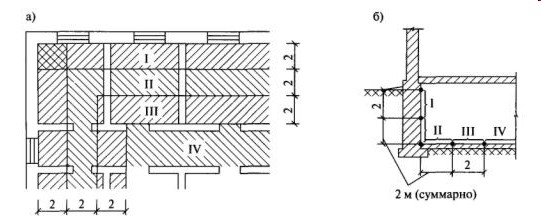 Breakdown of the floor surface (a) and recessed parts of the outer walls (b) into design zones I-IV
The transfer of heat from the room through the structure of the floor or wall and the thickness of the soil with which they come into contact is subject to complex laws. To calculate the resistance to heat transfer of structures located on the ground, a simplified method is used. The surface of the floor and walls (in this case, the floor is considered as a continuation of the wall) is divided along the ground into strips 2 m wide, parallel to the junction of the outer wall and the ground surface.
The counting of zones starts along the wall from the ground level, and if there are no walls along the ground, then zone I is the floor strip closest to the outer wall. The next two strips will be numbered II and III, and the rest of the floor will be zone IV. Moreover, one zone can begin on the wall and continue on the floor.
A floor or wall that does not contain insulating layers made of materials with a thermal conductivity coefficient of less than 1.2 W / (m ° C) is called non-insulated. The resistance to heat transfer of such a floor is usually denoted as R np, m 2 ° C / W. For each zone of an uninsulated floor, standard values of resistance to heat transfer are provided:
- zone I - RI \u003d 2.1 m 2 ° C / W;
- zone II - RII \u003d 4.3 m 2 ° C / W;
- zone III - RIII \u003d 8.6 m 2 ° C / W;
- zone IV - RIV \u003d 14.2 m 2 ° C / W.
If there are insulating layers in the construction of the floor located on the ground, it is called insulated, and its resistance to heat transfer R unit, m 2 ° C / W, is determined by the formula:
R pack \u003d R np + R us1 + R us2 ... + R usn
Where R np is the resistance to heat transfer of the considered zone of an uninsulated floor, m 2 · ° С / W;
R us - heat transfer resistance of the insulating layer, m 2 · ° С / W;
For a floor on logs, the heat transfer resistance Rl, m 2 · ° С / W, is calculated by the formula.
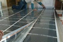
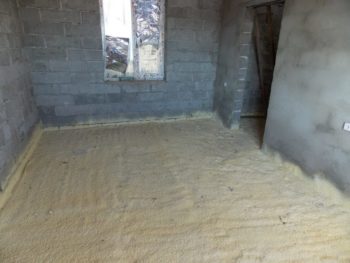
Soil preparation, insulation materials, waterproofing
Ground work
Preparation for the arrangement of the floor on the ground begins with the preparation of the soil. It is removed at the stage of land works, well rammed. Then they cover with waterproofing, make backfill.
Porous, hard bedding is equipped with road gravel. Crushed stone of a fraction of 2-3 cm is used, which is laid on a soil 15 cm thick, while it is tightly rammed.
At the corners of the walls mark the horizontal level, determine the zero mark of the flooring. These manipulations are done before the device of the top layer of the flooring pie.
Materials for insulation
Insulation material is exposed to a large number of negative influences: humidity, condensate, the activity of microorganisms, and others. Before choosing a material, they learn all the pros, cons of the material, optimal conditions for use. They must meet the following requirements: pressure strength, water resistance, low thermal conductivity. The most popular include:
Mineral wool - good for frame houses, easy to install, has good resistance to heat loss
However, it loses its qualities when wet and when using it, great attention is paid to the waterproofing device.
Foam glass is an absolute heat insulator, it is easily cut, joined with glue, which eliminates the appearance of cold bridges, and is resistant to compression. Used for arranging concrete monolithic coatings.
 Floor insulation with polyurethane foam
Foamed polyurethane - spraying agent is sold in cylinders. Fill with foam all the gaps, the space between the parts of the floor, the bottom of the pit on the ground.After hardening, a solid array does not conduct heat, but releases slightly toxic substances for 7 days after use.
Waterproofing
The floor of any kind (wooden, concrete), which is done on the ground, must be insulated from moisture. To do this, a variety of waterproofing is included in the floor cake.
Polyethylene film (one-, two-layer), which is laid on a layer of sand bedding. The edges of the film are tucked to the walls with bituminous mastic, and the strips are overlapped, connecting with silicone and adhesive tape. Also used roofing material, banner fabric, rolled floor waterproofing.
Floors, which include wool, are prohibited from complete isolation with a continuous hydro-barrier - it will lead to evaporation, condensate. Coating waterproofing is used here, roofing material is laid on the ground.
The device of the floor on the ground is not difficult. The main thing is to choose the right layout for the pie, study all the technical characteristics of the materials used, calculate the strength of the base, heat loss, in order to properly make a high-quality coating.
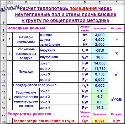
Calculation in Excel of heat loss through the floor and walls adjacent to the ground according to the generally accepted zonal method by V.D. Machinsky.
The temperature of the soil under the building depends primarily on the thermal conductivity and heat capacity of the soil itself and on the ambient air temperature in the area during the year. Since the temperature of the outside air varies significantly in different climatic zones, the soil also has different temperatures in different periods of the year at different depths in different areas.
To simplify the solution of the complex problem of determining heat loss through the floor and walls of the basement into the ground, for more than 80 years, the method of dividing the area of enclosing structures into 4 zones has been successfully used.
Each of the four zones has its own fixed heat transfer resistance in m 2 °C / W:
R1
\u003d 2.1 R 2
\u003d 4.3 R 3
\u003d 8.6 R 4
=14,2
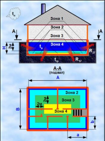
Zone 1 is a strip on the floor (in the absence of soil penetration under the building) 2 meters wide, measured from the inner surface of the outer walls along the entire perimeter or (in the case of a subfloor or basement) a strip of the same width, measured down the inner surfaces of the outer walls from soil edges.
Zones 2 and 3 are also 2 meters wide and are located behind zone 1 closer to the center of the building.
Zone 4 occupies the entire remaining central square.
In the picture below, zone 1 is located entirely on the basement walls, zone 2 is partially on the walls and partially on the floor, zones 3 and 4 are completely on the basement floor.
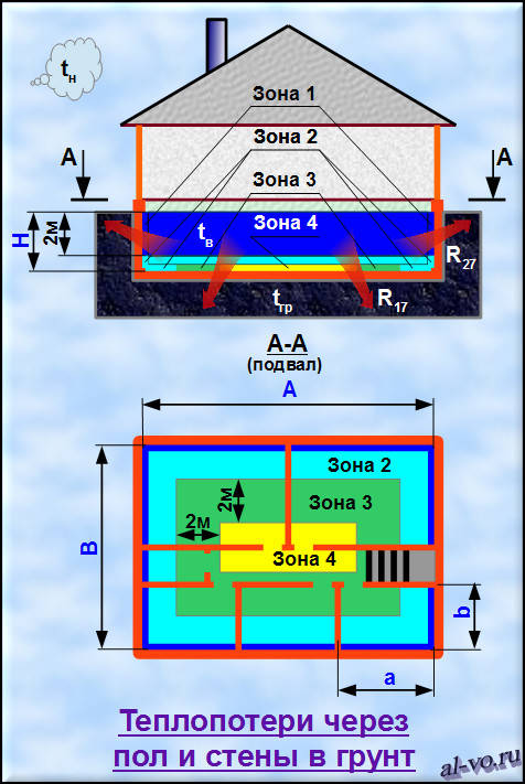
If the building is narrow, then zones 4 and 3 (and sometimes 2) may simply not be.
Floor area
zone 1 in the corners is counted twice in the calculation!
If the entire zone 1 is located on vertical walls, then the area is considered in fact without any additions.
If part of zone 1 is on the walls and part is on the floor, then only the corner parts of the floor are counted twice.
If the entire zone 1 is located on the floor, then the calculated area should be increased by 2 × 2x4 = 16 m 2 when calculating (for a rectangular house in plan, i.e. with four corners).
If there is no deepening of the structure into the ground, then this means that H
=0.
Below is a screenshot of the Excel calculation program for heat loss through the floor and recessed walls. for rectangular buildings
.
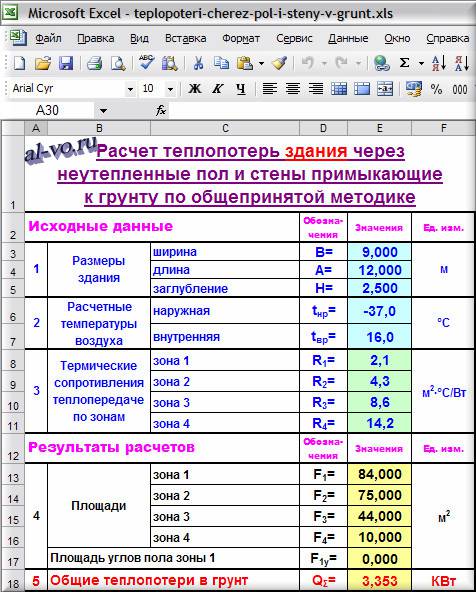
Zone areas F
1
,
F
2
,
F
3
,
F
4
calculated according to the rules of ordinary geometry. The task is cumbersome and often requires sketching. The program greatly facilitates the solution of this problem.
The total heat loss to the surrounding soil is determined by the formula in kW:
Q Σ
=((F
1
+
F
1y
)/
R
1
+
F
2
R
2
+
F
3
R
3
+
F
4
R
4
)*(t
vr
-t nr
)/1000
The user only needs to fill in the first 5 lines in the Excel table with values and read the result below.
To determine heat losses to the ground premises
zone areas will have to be calculated manually.
and then substitute in the above formula.
The following screenshot shows, as an example, the calculation in Excel of heat loss through the floor and recessed walls. for the lower right (according to the figure) basement room
.
The sum of heat losses to the ground by each room is equal to the total heat losses to the ground of the entire building!
The figure below shows simplified diagrams of typical floor and wall structures.
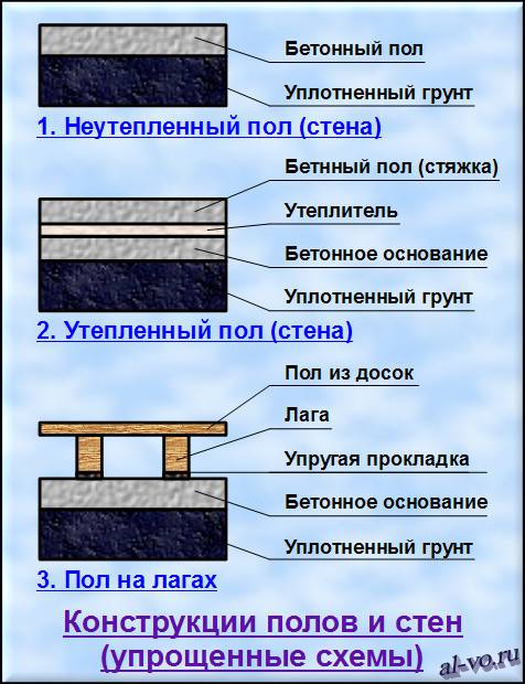
The floor and walls are considered non-insulated if the coefficients of thermal conductivity of materials (λ
i
), of which they are composed, is more than 1.2 W / (m ° C).
If the floor and / or walls are insulated, that is, they contain layers with λ
W / (m ° C), then the resistance is calculated for each zone separately according to the formula:
R
insulation
i
=
R
non-insulated
i
+
Σ
(δ
j
/λ
j
)
Here δ
j
- the thickness of the insulation layer in meters.
For floors on logs, heat transfer resistance is also calculated for each zone, but using a different formula:
R
on the logs
i
=1,18*(R
non-insulated
i
+
Σ
(δ
j
/λ
j
)
)
7 Thermal engineering calculation of light openings
V
practice of construction of residential and
public buildings applied
single, double and triple glazing
in wood, plastic or
metal bound, twin
or separate. Thermal engineering calculation
balcony doors and light fillings
openings, as well as the choice of their designs
carried out depending on the area
construction and premises.
Required
thermal total resistance
heat transfer
 ,
,
(m2 С)/W,
for light openings are determined in
depending on the value of Dd
(table 10).
Then
by value

choose
the design of the light opening with the reduced
heat transfer resistance
 provided
 ≥
≥
(table 13).
table
13 - Actual reduced resistance
windows, balcony doors and skylights
|
filling |
Reduced |
|
|
v |
v |
|
|
single |
0,18 |
− |
|
single |
0,15 |
− |
|
double glazing bindings |
0,4 |
− |
|
double glazing bindings |
0,44 |
0,34* |
|
Blocks |
0.31 (without binding) |
|
|
244 |
0.33 (without binding) |
|
|
Profile |
0.31 (without binding) |
|
|
Double |
0,36 |
− |
 ,
,
Table continuation
13
|
filling |
Reduced |
|
|
v |
v |
|
|
triple out skylights |
0,52 |
− |
|
Triple |
0,55 |
0,46 |
|
single chamber
out of the ordinary |
0,38 |
0,34 |
|
glass with coated |
0,51 |
0,43 |
|
glass with coated |
0,56 |
0,47 |
|
Double chamber
out of the ordinary |
0,51 |
0,43 |
|
out of the ordinary |
0,54 |
0,45 |
|
glass with coated |
0,58 |
0,48 |
|
glass with coated |
0,68 |
0,52 |
|
glass with
coated |
0,65 |
0,53 |
|
Normal
out of the ordinary |
0,56 |
− |
|
glass with coated |
0,65 |
− |
|
glass with
coated |
0,69 |
− |
|
Normal |
0,68 |
− |
|
glass with coated |
0,74 |
− |
|
glass with coated |
0,81 |
−* |
|
glass with
coated |
0,82 |
− |
 ,
,Continuation
tables 13
|
filling |
Reduced |
|
|
v |
v |
|
|
Two single chamber
paired |
0,7 |
− |
|
Two single chamber
separate |
0,74 |
− |
|
Four-layer
paired |
0,8 |
− |
|
Notes: * - |
 ,
,
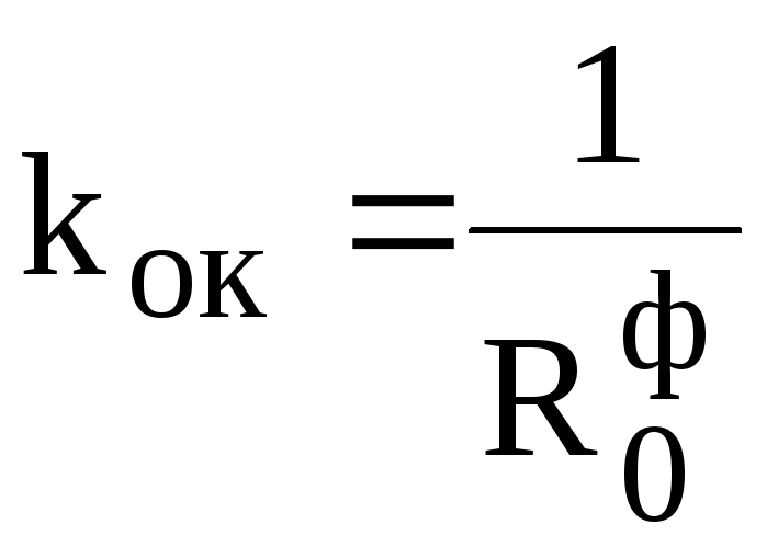
For
accepted design of the light opening
heat transfer coefficient kOK,
W/(m2 С),
is determined by the equation:
 .
.
Example
5. Thermotechnical calculation of light
openings
Initial
data.
-
Building
residential, tv
= 20С
(table
1). -
District
construction -
Penza. -
txp(0.92)
\u003d -29С;
top
= -3.6С;
zop
= 222 days (Appendix A, Table A.1);
 C day
C day
Order
calculation.
-
We define
=
0.43 (m2 С)/W,
(table 10). -
Choose
window design (table 13) depending on
from the valuetaking into account the fulfillment of condition (7). So
Thus, for our example, we take
wooden double glazed window
separate bindings, with the actual
heat transfer resistance
= 0.44 (m2 С)/W.
Coefficient
heat transfer glazing (windows) kOK
determined by
formula:
 W/(m2 C).
P.S. 02/25/2016
Almost a year after writing the article, we managed to deal with the questions raised a little higher.
Firstly, the program for calculating heat losses in Excel according to the method of A.G. Sotnikova thinks everything is correct - exactly according to the formulas of A.I. Pehovich!
Secondly, the formula (3) from the article by A.G. Sotnikova should not look like this:
R
27
=
δ
conv.
/(2*λ gr
)=K(cos
((h
H
)*(π/2)))/К(sin
((h
H
)*(π/2)))
In the article by A.G. Sotnikova is not a correct entry! But then the graph is built, and the example is calculated according to the correct formulas!!!
So it should be according to A.I. Pekhovich (p. 110, additional task to item 27):
R
27
=
δ
conv.
/λ gr
=1/(2*λ gr
)*TO(cos
((h
H
)*(π/2)))/К(sin
((h
H
)*(π/2)))
δ
conv.
=R
27
*λ gr
=(½)*K(cos
((h
H
)*(π/2)))/К(sin
((h
H
)*(π/2)))
Usually, floor heat losses in comparison with similar indicators of other building envelopes (external walls, window and door openings) are a priori assumed to be insignificant and are taken into account in the calculations of heating systems in a simplified form. Such calculations are based on a simplified system of accounting and correction coefficients for the resistance to heat transfer of various building materials.
Considering that the theoretical justification and methodology for calculating the heat loss of the ground floor was developed quite a long time ago (i.e. with a large design margin), we can safely say that these empirical approaches are practically applicable in modern conditions. The coefficients of thermal conductivity and heat transfer of various building materials, insulation and floor coverings are well known, and other physical characteristics are not required to calculate heat loss through the floor. According to their thermal characteristics, floors are usually divided into insulated and non-insulated, structurally - floors on the ground and logs.
The calculation of heat loss through an uninsulated floor on the ground is based on the general formula for estimating heat loss through the building envelope:
where Q
are the main and additional heat losses, W;
A
is the total area of the enclosing structure, m2;
tv
, tn
- temperature inside the room and outside air, °C;
β
— share of additional heat losses in total;
n
- correction factor, the value of which is determined by the location of the enclosing structure;
Ro
– resistance to heat transfer, m2 °С/W.
Note that in the case of a homogeneous single-layer floor slab, the heat transfer resistance Ro is inversely proportional to the heat transfer coefficient of the uninsulated floor material on the ground.
When calculating heat loss through an uninsulated floor, a simplified approach is used, in which the value (1+ β) n = 1. Heat loss through the floor is usually carried out by zoning the heat transfer area. This is due to the natural heterogeneity of the temperature fields of the soil under the floor.
The heat loss of an uninsulated floor is determined separately for each two-meter zone, the numbering of which starts from the outer wall of the building. In total, four such strips 2 m wide are taken into account, considering the soil temperature in each zone to be constant. The fourth zone includes the entire surface of the uninsulated floor within the boundaries of the first three strips. Heat transfer resistance is accepted: for the 1st zone R1=2.1; for the 2nd R2=4.3; respectively for the third and fourth R3=8.6, R4=14.2 m2*оС/W.
Fig.1. Zoning of the floor surface on the ground and adjacent recessed walls when calculating heat losses
In the case of recessed rooms with a soil base of the floor: the area of the first zone adjacent to the wall surface is taken into account twice in the calculations. This is quite understandable, since the heat loss of the floor is added to the heat loss in the vertical enclosing structures of the building adjacent to it.
Calculation of heat loss through the floor is made for each zone separately, and the results obtained are summed up and used for the thermal engineering justification of the building project. The calculation for the temperature zones of the outer walls of recessed rooms is carried out according to formulas similar to those given above.
In calculations of heat loss through an insulated floor (and it is considered as such if its structure contains layers of material with a thermal conductivity of less than 1.2 W / (m ° C)) the value of the heat transfer resistance of an uninsulated floor on the ground increases in each case by the heat transfer resistance of the insulating layer:
Ru.s = δy.s / λy.s
,
where δy.s
– thickness of the insulating layer, m; λu.s
- thermal conductivity of the material of the insulating layer, W / (m ° C).
Thermal balance of the room
In buildings, structures and premises with a constant thermal regime during the heating season, to maintain the temperature at a given level, heat losses and heat gains are compared in the calculated steady state, when the greatest heat deficit is possible.
When reducing the heat balance in residential buildings, household heat emissions are taken into account.
The heat output of the heating installation of the room Qfrom to compensate for the heat deficit is equal to:
Qot \u003d Qpot - Qvyd (5)
where Qpot and Qout are heat losses and heat releases in the room at a given moment in time.
Heat losses in rooms in general form consist of heat losses through the building envelope Qlimit, as well as for heating materials, equipment and transport coming from outside Qmat. Heat consumption can also be during the evaporation of liquid and other endothermic technological processes Qtechn, with air for ventilation at a lower temperature compared to the room temperature Qvent, i.e.
(6)
Heat emissions in rooms in general form are made up of heat transfer by people Ql, heat pipelines of heating, technological equipment Qb, heat emissions by artificial lighting sources and operating electrical equipment Qel, heated materials and products Qmat, heat input from exothermic processes Qtech and solar radiation Qs.r, i.e. .
(7)
Such heat gains through the enclosing structure from adjacent rooms are taken into account. The heat balance for identifying a deficit or excess of heat is based on sensible heat (causing a change in room air temperature)
Taking into account during the estimated period of time the maximum heat loss (taking into account the security factor) and the minimum stable heat release
The heat balance for identifying a deficit or excess of heat is based on sensible heat (causing a change in room air temperature)
Taking into account during the estimated period of time the maximum heat loss (taking into account the security factor) and the minimum stable heat release
The calculation of the above heat losses is carried out according to the methodology given in SNiP 2.04.05-91 * "Heating, ventilation and air conditioning".