What else is taken into account when calculating the gas pipeline
As a result of friction against the walls, the gas velocity across the pipe cross section is different - it is faster in the center. However, the average indicator is used for calculations - one conditional speed.
There are two types of movement through pipes: laminar (jet, typical for pipes with a small diameter) and turbulent (has a disordered nature of movement with the involuntary formation of vortices anywhere in a wide pipe).
 Calculation of the diameter of the main gas supply pipeline
The gas moves not only because of the external pressure exerted on it. Its layers exert pressure on each other. Therefore, the hydrostatic head factor is also taken into account.
Pipe materials also affect the speed of movement. So in steel pipes during operation, the roughness of the inner walls increases and the axes narrow due to overgrowth. Polyethylene pipes, on the contrary, increase in internal diameter with a decrease in wall thickness. All this is taken into account at the design pressure.
Two-pipe home heating system features of calculation, diagrams and installation
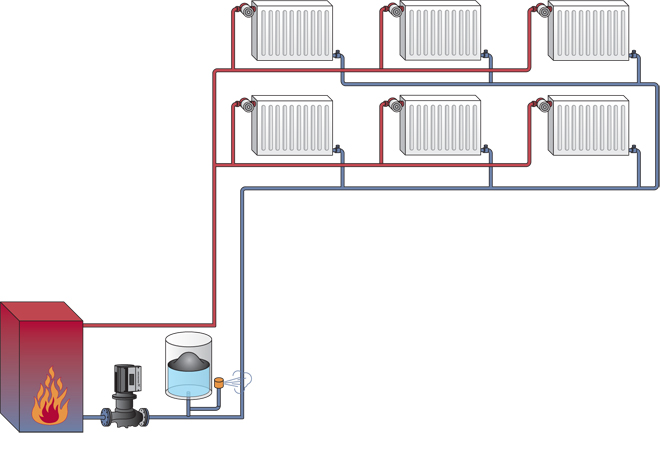
Even despite the relatively simple installation process and the relatively short length of the pipeline in the case of single-pipe heating systems, two-pipe heating systems still remain in the first positions on the specialized equipment market.
Although a short, but very convincing and informative list of the advantages and disadvantages of a two-pipe heating system, it justifies the purchase and subsequent use of circuits with a direct and return line.
Therefore, many consumers prefer it to other varieties, turning a blind eye to the fact that the installation of the system is not so easy.
How to work in EXCEL
The use of Excel spreadsheets is very convenient, since the results of the hydraulic calculation are always reduced to a tabular form. It is enough to determine the sequence of actions and prepare the exact formulas.
Entering initial data
A cell is selected and a value is entered. All other information is simply taken into account.
- the value of D15 is recalculated in liters, so it is easier to perceive the flow rate;
- cell D16 - add formatting according to the condition: "If v does not fall in the range of 0.25 ... 1.5 m / s, then the background of the cell is red / the font is white."
For pipelines with a height difference between the inlet and outlet, static pressure is added to the results: 1 kg / cm2 per 10 m.
Registration of results
The author's color scheme carries a functional load:
- Light turquoise cells contain the original data - they can be changed.
- Pale green cells are input constants or data that is little subject to change.
- Yellow cells are auxiliary preliminary calculations.
- Light yellow cells are the results of calculations.
- Fonts:
- blue - initial data;
- black - intermediate/non-main results;
- red - the main and final results of the hydraulic calculation.
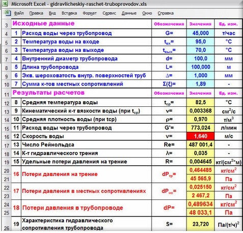
Results in an Excel spreadsheet
Example from Alexander Vorobyov
An example of a simple hydraulic calculation in Excel for a horizontal pipeline section.
- pipe length 100 meters;
- ø108 mm;
- wall thickness 4 mm.

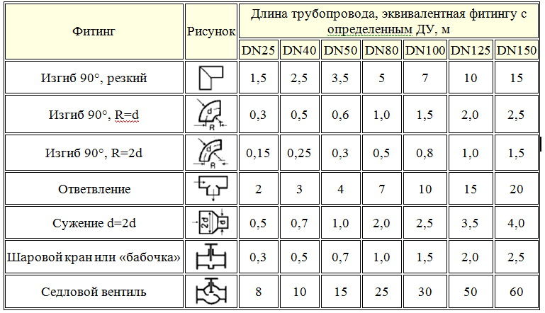
Table of local resistance calculation results
Complicating step by step calculations in Excel, you better master the theory and partially save on design work. Thanks to a competent approach, your heating system will become optimal in terms of costs and heat transfer.
Heating with two mains
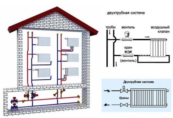
A distinctive feature of the structure of the design of a two-pipe heating system consists in two pipeline branches.
The first conducts and directs the water heated in the boiler through all the necessary devices and devices.
The other one collects and removes the water already cooled during operation and sends it to the heat generator.
In a single-pipe form of the system design, water, unlike a two-pipe one, where it is conducted through all pipes of heating devices with the same temperature indicator, undergoes a significant loss of the characteristics necessary for a stable heating process on the way to the closing part of the pipeline.
The length of the pipes and the costs directly associated with it double when choosing a two-pipe heating system, but this is a relatively minor nuance against the background of obvious advantages.
Firstly, for the creation and installation of a two-pipe design of the heating system, pipes with a large diameter value will not be needed at all and, therefore, this or that obstacle will not be created on the way, as is the case with a single-pipe circuit.
All the necessary fasteners, valves and other structural details are also much smaller in size, so the difference in cost will be very imperceptible.
One of the main advantages of such a system is that it is possible to mount it near each of the thermostat banks and significantly reduce costs and increase ease of use.
In addition, the thin ramifications of the supply and return lines also do not interfere with the integrity of the interior of the living space, besides, they can simply be hidden behind the sheathing or in the wall itself.
Having sorted out all the advantages and nuances of both heating systems, the owners, as a rule, still prefer to choose a two-pipe system. However, it is necessary to choose one of several options for such systems, which, according to the owners themselves, will be the most functional and rational in use.
Classification of gas pipelines
Modern gas pipelines are a whole system of complexes of structures designed to transport combustible fuel from its production sites to consumers. Therefore, according to their purpose, they are:
- Trunk - for transportation over long distances from production sites to destinations.
- Local - for the collection, distribution and supply of gas to the facilities of settlements and enterprises.

Compressor stations are being built along the main routes, which are needed to maintain working pressure in the pipes and supply gas to designated points to consumers in the required volumes calculated in advance. In them, the gas is cleaned, dried, compressed and cooled, and then returned to the gas pipeline under a certain pressure required for a given section of the fuel passage.
Local gas pipelines located in settlements are classified:
- By type of gas - natural, liquefied hydrocarbon, mixed, etc. can be transported.
- By pressure - in different areas, gas can be with low, medium and high pressure.
- By location - external (street) and internal, aboveground and underground.
Hydraulic calculation of a 2-pipe heating system
- Hydraulic calculation of the heating system, taking into account pipelines
- An example of hydraulic calculation of a two-pipe gravity heating system
What is the hydraulic calculation of a two-pipe heating system for? Each building is individual. In this regard, heating with the determination of the amount of heat will be individual. This can be done using hydraulic calculation, while the program and the calculation table can facilitate the task.
The calculation of the heating system at home begins with the choice of fuel, based on the needs and characteristics of the infrastructure of the area where the house is located.
The purpose of the hydraulic calculation, the program and table of which is available on the net, is as follows:
- determining the number of heating devices that are needed;
- calculation of the diameter and number of pipelines;
- determination of possible loss of heating.
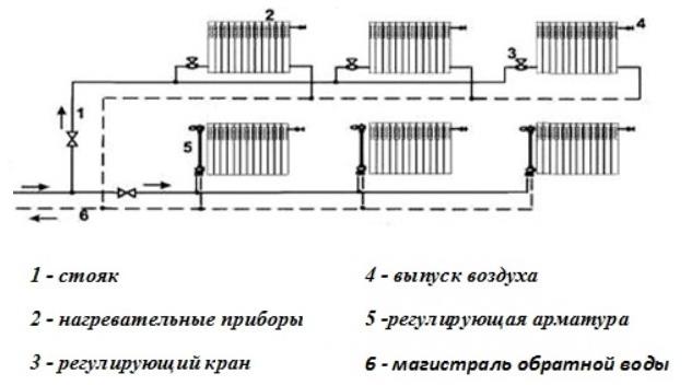
All calculations must be made according to the heating scheme with all the elements that are included in the system.Such a scheme and table must be preliminarily drawn up. To carry out a hydraulic calculation, you will need a program, an axonometric table and formulas.
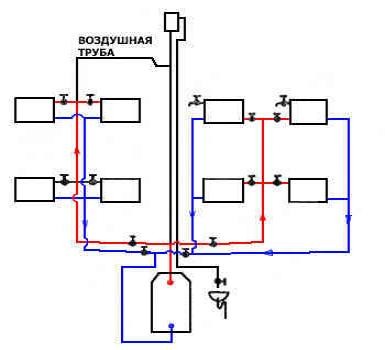
Two-pipe heating system of a private house with a lower wiring.
A more loaded pipeline ring is taken as the design object, after which the required pipeline cross-section, possible pressure losses of the entire heating circuit, and the optimal surface area of the radiators are determined.
Carrying out such a calculation, for which a table and a program are used, can create a clear picture with the distribution of all resistances in the heating circuit that exist, and also allows you to obtain accurate parameters of the temperature regime, water flow in each part of the heating.
As a result, hydraulic calculation should build the most optimal heating plan for your own home. You don't have to rely solely on your intuition. The table and the calculation program will simplify the process.
Items you need:
Basic equations of hydraulic calculation of a gas pipeline
To calculate the movement of gas through pipes, the values of the pipe diameter, fuel consumption and pressure loss are taken. Calculated depending on the nature of the movement. With laminar - calculations are made strictly mathematically according to the formula:
Р1 – Р2 = ∆Р = (32*μ*ω*L)/D2 kg/m2 (20), where:
- ∆Р – kgm2, head loss due to friction;
- ω – m/s, fuel speed;
- D - m, pipeline diameter;
- L - m, pipeline length;
- μ is kg sec/m2, fluid viscosity.

With turbulent motion, it is impossible to apply accurate mathematical calculations due to the randomness of the motion. Therefore, experimentally determined coefficients are used.
Calculated according to the formula:
Р1 – Р2 = (λ*ω2*L*ρ)/2g*D (21), where:
- P1 and P2 are pressures at the beginning and end of the pipeline, kg/m2;
- λ is the dimensionless drag coefficient;
- ω – m/sec, the average speed of gas flow over the pipe section;
- ρ – kg/m3, fuel density;
- D - m, pipe diameter;
- g – m/sec2, acceleration due to gravity.
Video: Fundamentals of hydraulic calculation of gas pipelines
A selection of questions
- Mikhail, Lipetsk — What discs for metal cutting should be used?
- Ivan, Moscow — What is the GOST of metal-rolled sheet steel?
- Maksim, Tver — What are the best racks for storing rolled metal products?
- Vladimir, Novosibirsk — What does ultrasonic processing of metals mean without the use of abrasive substances?
- Valery, Moscow — How to forge a knife from a bearing with your own hands?
- Stanislav, Voronezh — What equipment is used for the production of galvanized steel air ducts?
2 Specific linear pressure loss method
Sequence
hydraulic calculation by the method of specific
linear pressure loss:
a) is drawn
axonometric diagram of a heating system
(M 1:100).
On the
axonometric scheme is selected
main circulation ring. For
hydraulic calculation
choose the most loaded ring,
which is the calculated (main),
and secondary ring (application
G).When
dead-end movement of the coolant
the main circulation ring passes
through the most loaded and remote
from the thermal center (node) riser, at
passing movement - through the most
loaded middle riser.
b) main circulation
the ring is divided into calculated sections,
designated by a serial number (starting
from the reference riser); consumption is indicated
coolant in section G
, kg/h, section length l,
m;
c) for preliminary
selection of pipe diameters are determined
average specific pressure loss per
friction:
,
Pa/m (5.3)
where j
- coefficient taking into account the share of losses
pressure on pipelines and risers, j=0.3
– for highways, j=0.7
- for risers;
∆pR - disposable
pressure in the heating system, Pa,
∆pR=25 kPa - for
coolantG=105
WITH.
d) by the value of RWedand
coolant flow rate in section G (Appendix E) are
preliminary pipe diameters d,
mm, actual specific pressure loss
R, Pa/m, actual
coolant speed υ,
m/s. The received data is entered into
table 5.2.
e) losses are determined
pressure in the areas:
,
Pa (5.4)
where R is
specific friction pressure losses,
Pa/m;
l is the length of the section, m;
Z
– pressure loss on local resistances,
pa,
;
(5.5)
ξ - coefficient,
taking into account local resistance on
site, (appendices B, C);
ρ - density
coolant, kg/m3,
(Appendix D);
υ - coolant velocity
on the site, m / s, (Appendix E);
f) after preliminary
selection of pipe diameters is performed
hydraulic balancing, which should not
exceed 15%.
g) if the linkage passes,
then begin to perform the calculation of secondary
circulation rings (similarly), if
if not, then they are installed in the right areas
washers. The washer diameter is selected according to
formula:
,
mm, (5.6)
where
Gst
– coolant flow rate in the riser, kg/h,
(table 3.3);
Rsh
- the required pressure loss in the washer,
Pa.
diaphragms
installed at the crane on the base
riser at the point of connection to the supply
highways.
diaphragms
less than 5 mm in diameter are not installed.
By
calculation results are filled
tables 5.2, 5.3.
1.
Column 1
- put down the numbers of the sections;
2.
Column 2
- in accordance with the axonometric
by section we write down the thermal
load, Q,
W;
3.
We calculate the water consumption in the reference
riser for the calculated section (formula
5.1), column 3:
4.
According to table 4.2 for diameter
riser Dat,
mm choose the diameters of the liner and
trailing section: Dy(P),
mm; Dy(h),
mm.
5.
We calculate the coefficients of local
resistance in section 1 (applications
B, C), we write the amount in column 10 of the tables
5.2, 5.3.
On the
border of two sections local resistance
attributed to the area with lower consumption
water.
results
calculations are summarized in Table 5.1.
table
5.1 - Local resistances on the calculated
plots
-
plot number,
type of local resistance
For example: Plot
32
tee per pass, =1;account(3)=
2x1=2For instance:
Riser 31)
cast iron radiator - 3 pcs., =1.4;2)
double regulation valve
– 6 pieces, =13;3)
bend bent at an angle of 90
– 6 pieces, =0.6;4)
ordinary direct flow valve -
2 pieces, =3;5)
tee swivel to branch -
2 pieces, =1.5.st3
= 3x1.4+ + 6x13 + 6x0.6 + 2x3 + 2x1.5 = 96.2
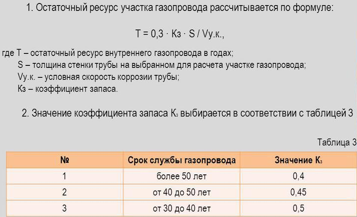
Why is it necessary to calculate the gas pipeline
Calculations are carried out throughout all sections of the gas pipeline to identify places where possible resistances are likely to appear in the pipes, changing the fuel supply rate.
If all calculations are done correctly, then the most suitable equipment can be selected and an economical and efficient design of the entire structure of the gas system can be created.
This will save you from unnecessary, overestimated indicators during operation and costs in construction, which could be during the planning and installation of the system without hydraulic calculation of the gas pipeline.
There is a better opportunity to select the required sectional size and pipe materials for more efficient, fast and stable supply of blue fuel to the planned points of the gas pipeline system.
The optimal operating mode of the entire gas pipeline is ensured.
Developers receive financial benefits from savings on the purchase of technical equipment and building materials.
The correct calculation of the gas pipeline is made, taking into account the maximum levels of fuel consumption during periods of mass consumption. All industrial, municipal, individual household needs are taken into account.
Program overview
For the convenience of calculations, amateur and professional programs for calculating hydraulics are used.
The most popular is Excel.
You can use the online calculation in Excel Online, CombiMix 1.0, or the online hydraulic calculator.The stationary program is selected taking into account the requirements of the project.
The main difficulty in working with such programs is ignorance of the basics of hydraulics. In some of them, there is no decoding of formulas, the features of branching of pipelines and the calculation of resistances in complex circuits are not considered.
- HERZ C.O. 3.5 - makes a calculation according to the method of specific linear pressure losses.
- DanfossCO and OvertopCO can count natural circulation systems.
- "Flow" (Flow) - allows you to apply the calculation method with a variable (sliding) temperature difference along the risers.
You should specify the data entry parameters for temperature - Kelvin / Celsius.
Calculation of the volume of water and the capacity of the expansion tank
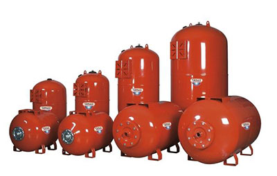 The volume of the expansion tank should be equal to 1/10 of the total volume of liquid
To calculate the performance of the expansion tank, which is mandatory for any closed-type heating system, you will need to understand the phenomenon of increasing the volume of liquid in it. This indicator is estimated taking into account changes in the main performance characteristics, including fluctuations in its temperature. In this case, it varies in a very wide range - from room temperature +20 degrees and up to operating values within 50-80 degrees.
It will be possible to calculate the volume of the expansion tank without unnecessary problems, if you use a rough estimate that has been proven in practice. It is based on the experience of operating the equipment, according to which the volume of the expansion tank is approximately one tenth of the total amount of coolant circulating in the system.
At the same time, all its elements are taken into account, including heating radiators (batteries), as well as the water jacket of the boiler unit. To determine the exact value of the desired indicator, you will need to take the passport of the equipment in use and find in it the items relating to the capacity of the batteries and the working tank of the boiler
After their determination, it is not difficult to find the excess coolant in the system. To do this, the cross-sectional area of polypropylene pipes is first calculated, and then the resulting value is multiplied by the length of the pipeline. After summing up for all branches of the heating system, the numbers taken from the passport for radiators and the boiler are added to them. One tenth of the total is then counted.
Calculation of coolant parameters
 The amount of coolant in 1 m of pipe, depending on the diameter
The calculation of the coolant is reduced to the determination of the following indicators:
- the speed of movement of water masses through the pipeline with the given parameters;
- their average temperature;
- carrier consumption associated with the performance requirements of heating equipment.
Known formulas for calculating the parameters of the coolant (taking into account hydraulics) are quite complex and inconvenient in practical application. Online calculators use a simplified approach that allows you to get a result with an error allowed for this method.
Nevertheless, before starting installation, it is important to take care to purchase a pump with indicators not lower than the calculated ones. Only in this case, there is confidence that the requirements for the system according to this criterion are fully met and that it is able to heat the room to comfortable temperatures.
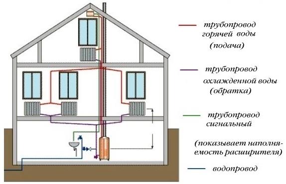
Horizontal and vertical schemes
Such a heating system is divided into horizontal and vertical schemes according to the location of the pipeline connecting all devices and appliances into one.
The vertical heating circuit differs from others in that in this case all the necessary devices are connected to a vertical riser.
Although its compilation will end up being a little more expensive, the resulting air stagnation and traffic jams will not interfere with stable operation.This solution is most suitable for apartment owners in a house with many floors, since all individual floors are connected separately.
A two-pipe heating system with a horizontal layout is perfect for a one-story residential building with a relatively large length, in which it is easier and more rational to connect all existing radiator compartments to a horizontal pipeline.
Both types of heating system circuits boast excellent hydraulic and thermal stability, only in the first situation, in any case, it will be necessary to calibrate the risers located vertically, and in the second - horizontal loops.
Simple pipeline of constant cross section
Main
calculated ratios for simple
pipeline are: equation
Bernoulli, Q flow equation
= const
and formulas for calculating pressure losses on
friction along the length of the pipe and in local
resistance .
At
application of the Bernoulli equation in
specific calculation can take into account
the recommendations below. First
should be set in the figure two calculated
section and plane of comparison. V
as sections it is recommended to take:
free
the surface of the liquid in the tank, where
the speed is zero, i.e. V
= 0;
exit
flow into the atmosphere, where the pressure in
jet cross section is equal to the ambient pressure
environment, i.e. Ra6c
= patm
or pout of 6
= 0;
section,
in which it is specified (or necessary
determine) pressure (manometer readings
or vacuum gauge)
section
below the piston where the overpressure
determined by the external load.
Plane
it is convenient to make comparisons through the center
gravity of one of the design sections,
usually located below (then
geometric section heights
 0).
0).
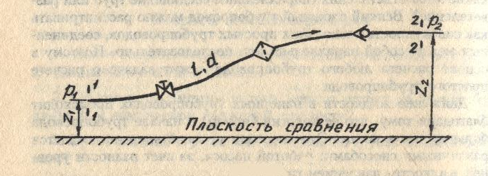
Let
simple pipeline of constant cross section
located randomly in space
(Fig. 1), has a total length l
and diameter d
and contains a number of local resistances.
In the initial section (1-1) geometric
height is z1
and overpressure p1,
and in the final (2-2) respectively z2
and p2.
The flow velocity in these sections due to
the constancy of the pipe diameter is the same
and equal to v.
The equation
Bernoulli for sections 1-1 and 2-2, taking into account
 ,
, will look like:

or
 ,
,
 sum
sum
local resistance coefficients.
For
convenience of calculations, we introduce the concept
design head
 .
.


 ,
,

 ٭
٭

 ٭٭
٭٭
Determination of pressure losses in pipes
The pressure loss resistance in the circuit through which the coolant circulates is determined as their total value for all individual components. The latter include:
- losses in the primary circuit, denoted as ∆Plk;
- local heat carrier costs (∆Plm);
- pressure drop in special zones, called “heat generators” under the designation ∆Ptg;
- losses inside the built-in heat exchange system ∆Pto.
After summing these values, the desired indicator is obtained, which characterizes the total hydraulic resistance of the system ∆Pco.
In addition to this generalized method, there are other ways to determine the head loss in polypropylene pipes. One of them is based on a comparison of two indicators tied to the beginning and end of the pipeline. In this case, the pressure loss can be calculated by simply subtracting its initial and final values, determined by two pressure gauges.
Another option for calculating the desired indicator is based on the use of a more complex formula that takes into account all the factors that affect the characteristics of the heat flux. The ratio given below primarily takes into account the loss of fluid head due to the long length of the pipeline.
- h is the liquid head loss, measured in meters in the case under study.
- λ is the coefficient of hydraulic resistance (or friction), determined by other calculation methods.
- L is the total length of the serviced pipeline, which is measured in running meters.
- D is the internal size of the pipe, which determines the volume of the coolant flow.
- V is the fluid flow rate, measured in standard units (meter per second).
- The symbol g is the free fall acceleration, which is 9.81 m/s2.
 Pressure loss occurs due to fluid friction on the inner surface of the pipes
Of great interest are the losses caused by the high coefficient of hydraulic friction. It depends on the roughness of the inner surfaces of the pipes. The ratios used in this case are valid only for tubular blanks of a standard round shape. The final formula for finding them looks like this:
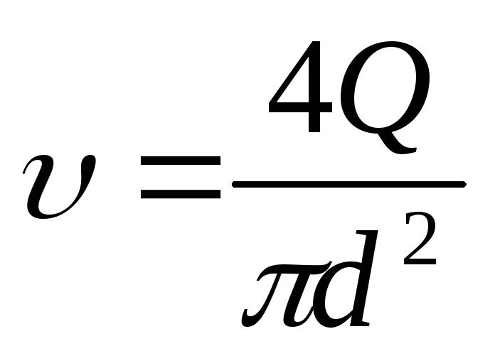
- V - the speed of movement of water masses, measured in meters / second.
- D - inner diameter, which determines the free space for the movement of the coolant.
- The coefficient in the denominator indicates the kinematic viscosity of the liquid.
The latter indicator refers to constant values and is found according to special tables published in large quantities on the Internet.
Calculation of the hydraulics of heating channels
 Properly calculated hydraulics allows you to correctly distribute the diameter of the pipes throughout the system
The hydraulic calculation of the heating system usually comes down to the selection of the diameters of the pipes laid in separate sections of the network. When it is carried out, the following factors must be taken into account:
- the pressure value and its drops in the pipeline at a given coolant circulation rate;
- its estimated expense;
- typical sizes of used tubular products.
When calculating the first of these parameters, it is important to take into account the power of the pumping equipment. It should be enough to overcome the hydraulic resistance of the heating circuits. In this case, the total length of polypropylene pipes is of decisive importance, with an increase in which the total hydraulic resistance of the systems as a whole increases.
Based on the results of the calculation, the indicators necessary for the subsequent installation of the heating system and corresponding to the requirements of current standards are determined
In this case, the total length of polypropylene pipes is of decisive importance, with an increase in which the total hydraulic resistance of the systems as a whole increases. Based on the results of the calculation, the indicators necessary for the subsequent installation of the heating system and corresponding to the requirements of the current standards are determined.