Manufacturing instructions
Blueprints


For the manufacture of the furnace you will need the following materials and tools:
- solder;
- textolite board.
- mini drill.
- radioelements.
- thermal paste.
- chemical reagents for board etching.
Additional materials and their features:
-
To make a coil
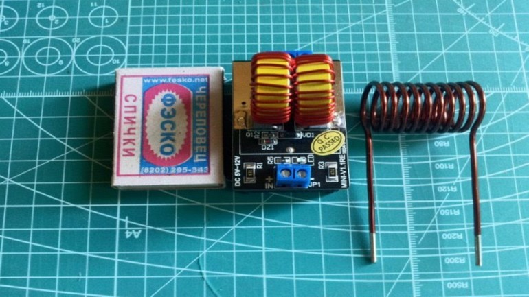
, which will emit an alternating magnetic field necessary for heating, it is necessary to prepare a piece of copper tube with a diameter of 8 mm and a length of 800 mm. -
Powerful power transistors
are the most expensive part of a homemade induction installation. To mount the frequency generator circuit, it is necessary to prepare 2 such elements. For these purposes, transistors of brands are suitable: IRFP-150; IRFP-260; IRFP-460. In the manufacture of the circuit, 2 identical of the listed field-effect transistors are used. -
For the manufacture of an oscillatory circuit
you will need ceramic capacitors with a capacity of 0.1 mF and an operating voltage of 1600 V. In order for a high power alternating current to form in the coil, 7 such capacitors are required. -
During the operation of such an induction device
, field-effect transistors will get very hot and if aluminum alloy radiators are not attached to them, then after a few seconds of operation at maximum power, these elements will fail. Putting transistors on heat sinks should be through a thin layer of thermal paste, otherwise the efficiency of such cooling will be minimal. -
Diodes
, which are used in an induction heater, must be of ultra-fast action. The most suitable for this circuit, diodes: MUR-460; UV-4007; HER-307. -
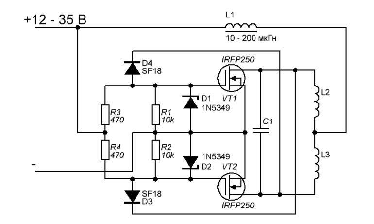
Resistors used in circuit 3:
10 kOhm with a power of 0.25 W - 2 pcs. and 440 ohm power - 2 watts. Zener diodes: 2 pcs. with an operating voltage of 15 V. The power of the zener diodes must be at least 2 watts. A choke for connecting to the power outputs of the coil is used with induction. -
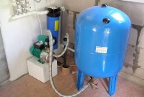
To power the entire device, you will need a power supply unit with a capacity of up to 500. W. and voltage 12 - 40 V.
You can power this device from a car battery, but you will not be able to get the highest power readings at this voltage.
 The very process of manufacturing an electronic generator and coil takes a little time and is carried out in the following sequence:
-
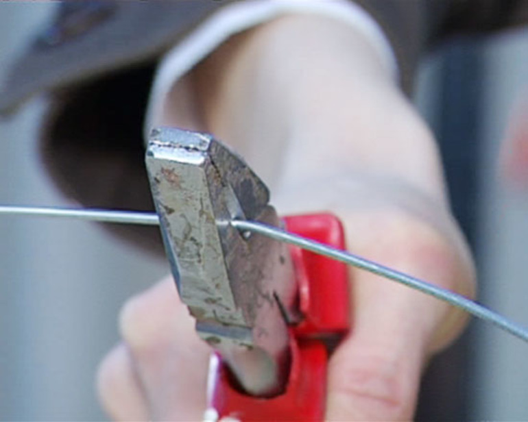
From a copper pipe
a spiral with a diameter of 4 cm is made. To make a spiral, a copper tube should be wound onto a rod with a flat surface with a diameter of 4 cm. The spiral should have 7 turns that should not touch. Mounting rings are soldered to the 2 ends of the tube for connection to the transistor radiators. -
The printed circuit board is made according to the scheme.
If it is possible to supply polypropylene capacitors, then due to the fact that such elements have minimal losses and stable operation at large amplitudes of voltage fluctuations, the device will work much more stable. The capacitors in the circuit are installed in parallel, forming an oscillatory circuit with a copper coil. -
Metal heating
occurs inside the coil, after the circuit is connected to a power supply or battery. When heating the metal, it is necessary to ensure that there is no short circuit of the spring windings. If you touch the heated metal 2 turns of the coil at the same time, then the transistors fail instantly.
Factors leading to the failure of the welding inverter
Situations that may cause failure of the inverter or lead to violations in its work, can be divided into two main types:
- associated with the wrong choice of welding mode;
- caused by the failure of parts of the device or their incorrect operation.
The method for identifying an inverter malfunction for subsequent repair is reduced to the sequential execution of technological operations, from the simplest to the most complex. The modes in which such checks are performed and what their essence is is usually specified in the instructions for the equipment.
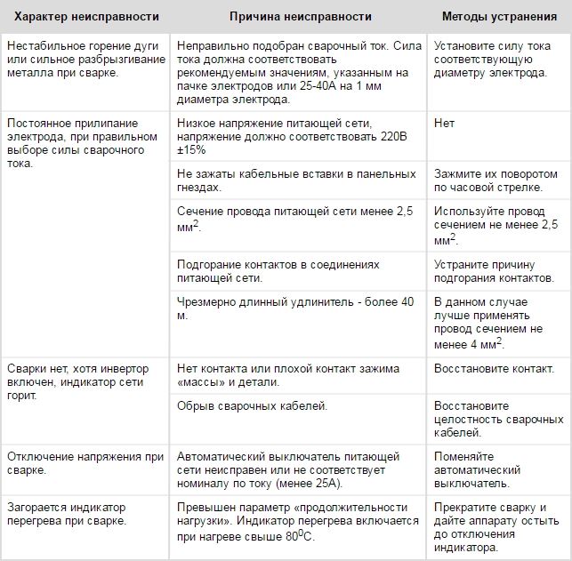
Common malfunctions of inverters, their causes and solutions
If the recommended actions did not lead to the desired results and the operation of the device was not restored, most often this means that the cause of the malfunction should be sought in the electronic circuit. The reasons for the failure of its blocks and individual elements may be different. We list the most common.
- Moisture has penetrated the inside of the unit, which may occur if the unit is exposed to precipitation.
- Dust has accumulated on the elements of the electronic circuit, which leads to a violation of their full cooling. The maximum amount of dust gets into the inverters when they are operated in very dusty rooms or on construction sites. In order to prevent the equipment from getting into such a state, its interior must be cleaned regularly.
- Overheating of the elements of the electronic circuit of the inverter and, as a result, their failure can be caused by non-compliance with the duty cycle (DU). This parameter, which must be strictly observed, is indicated in the technical data sheet of the equipment.
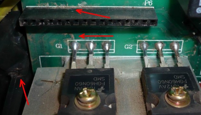
Traces of liquid ingress into the inverter housing
Buy parts on Aliexpress
|
Appliances that heat with electricity rather than gas are safe and convenient. Such heaters do not produce soot and unpleasant odors, but consume a large amount of electricity. An excellent way out is to assemble an induction heater with your own hands. This saves money and contributes to the family budget. There are many simple schemes according to which the inductor can be assembled independently.
In order to make it easier to understand the circuits and assemble the structure correctly, it would be useful to look into the history of electricity. Methods for heating metal structures with an electromagnetic coil current are widely used in the industrial manufacture of household appliances - boilers, heaters and stoves. It turns out that you can make a working and durable induction heater with your own hands.
The principle of operation of devices

The principle of operation of devices
The famous 19th century British scientist Faraday spent 9 years researching to convert magnetic waves into electricity. In 1931, a discovery was finally made, called electromagnetic induction. The wire winding of the coil, in the center of which there is a core of magnetic metal, creates a magnetic field under the power of alternating current. Under the action of vortex flows, the core heats up.
Faraday's discovery began to be used both in industry and in the manufacture of home-made motors and electric heaters. The first foundry based on a vortex inductor was opened in 1928 in Sheffield. Later, according to the same principle, the workshops of factories were heated, and for heating water, metal surfaces, connoisseurs assembled an inductor with their own hands.
The scheme of the device of that time is valid today. A classic example is an induction boiler, which includes:
- metal core;
- frame;
- thermal insulation.
The features of the circuit for accelerating the frequency of the current are as follows:
- industrial frequency of 50 Hz is not suitable for home-made devices;
- direct connection of the inductor to the network will lead to hum and low heating;
- effective heating is carried out at a frequency of 10 kHz.
Assembly according to schemes
Anyone familiar with the laws of physics can assemble an inductive heater with their own hands. The complexity of the device will vary from the degree of preparedness and experience of the master.
There are many video tutorials, following which you can create an effective device. It is almost always necessary to use the following basic components:
- steel wire with a diameter of 6-7 mm;
- copper wire for the inductor;
- metal mesh (to hold the wire inside the case);
- adapters;
- pipes for the body (made of plastic or steel);
- high frequency inverter.
This will be enough to assemble an induction coil with your own hands, and it is she who is at the heart of the instantaneous water heater. After preparing the necessary elements you can go directly to the manufacturing process of the device:
- cut the wire into segments of 6-7 cm;
- cover the inside of the pipe with a metal mesh and fill the wire to the top;
- similarly close the pipe opening from the outside;
- wind copper wire around the plastic case at least 90 times for the coil;
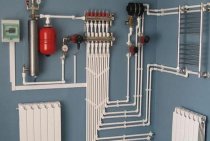
- insert the structure into the heating system;
- using an inverter, connect the coil to electricity.
According to a similar algorithm, you can easily assemble an induction boiler, for which you should:
- cut blanks from a steel pipe 25 by 45 mm with a wall no thicker than 2 mm;
- weld them together, connecting them with smaller diameters;
- weld iron covers to the ends and drill holes for threaded pipes;
- make a mount for an induction stove by welding two corners on one side;
- insert the hob into the mount from the corners and connect to the mains;
- add coolant to the system and turn on the heating.
Many inductors operate at a power not higher than 2 - 2.5 kW. Such heaters are designed for a room of 20 - 25 m²
If the generator is used in a car service, you can connect it to a welding machine, but it is important to consider certain nuances:
- You need AC, not DC like an inverter. The welding machine will have to be examined for the presence of points where the voltage does not have a direct direction.
- The number of turns to a wire of a larger cross section is selected by a mathematical calculation.
- Cooling of working elements will be required.
A few pictures
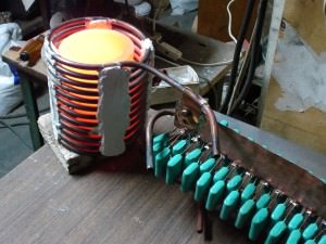
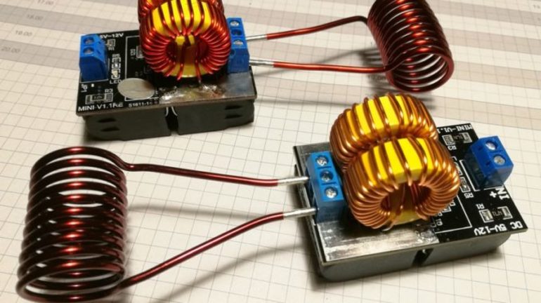
Instead of radiators, copper plates were used, which are soldered directly to the tube, since water cooling is used in this design. In my opinion, this is the most efficient cooling, because the transistors heat up well and no fans and super radiators will save them from overheating!
The cooling plates on the board are arranged in such a way that the coil tube passes through them. The plates and the tube need to be soldered together, for this I used a gas burner and a large soldering iron for soldering car radiators.
The capacitors are located on a two-sided textolite, the board is also soldered to the coil tube in a straight line, for better cooling.
The inductors are wound on ferrite rings, I personally took them out of a computer power supply, the wire was used in copper insulation.
The induction heater turned out to be quite powerful, it melts brass and aluminum very easily, it also melts iron parts, but a little slower. Since I used IRFP150 transistors, according to the parameters, the circuit can be powered with voltage up to 30 volts, so the power is limited only by this factor. So all the same I advise you to use IRFP250.
That's all! Below I will leave a video of the operation of the induction heater and a list of parts that can be bought on AliExpress at a very low price!
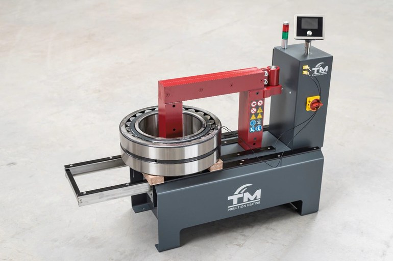
Principle of induction heating technology
The principle of induction heating technology is quite simple from a physical point of view. A coil formed from a current conductor generates a high-frequency magnetic field. In turn, a metal object placed in the inner region of the coil induces eddy currents. As a result, the object becomes very hot.
In parallel with the inductor, as a rule, a resonant capacitance is switched on.This step is taken to compensate for the inductive nature of the coil. The resonant circuit created by the coil-capacitor elements is excited at its own resonant frequency. The value of the excitation current is significantly less than the value of the current flowing through the inductor.