Basic Definitions of Theater Stage
The stage box is divided into three main parts along the vertical section: the hold, the flatbed and the grate (Fig. 1). The hold is a room located under the stage, so it is also called the lower stage. In the hold there are drive mechanisms of the circle, lifting and lowering platforms and other equipment. The lower stage is used for hatches-descents from the stage and for various effects.
The tablet is called the floor of the stage, a wooden flooring that serves as a place for the actors to play and set the scenery.
Grid-irons - the lattice ceiling of the stage. Blocks of decorative, individual, soffit lifts and other riding equipment are placed on the grate. At the level of the tablet, the stage from the side of the auditorium adjoins its front part - the proscenium, at the back - the rear stage room, and from the sides - the so-called pockets.
The proscenium is the part of the stage that extends into the auditorium beyond the line of the curtain. In modern theaters, the proscenium is often included in the volume of the stage box and is supplied with all the necessary set of mechanical equipment for changing the scenery. The front stage is used as a place for actors to play in front of the curtain in close proximity to the audience. It can be played both separately from the main stage, and in combination with it.
The border between the main stage and its front part is the red line - the line along which the intermission curtain passes.
The entire area of the stage is divided into conditional sections running parallel to the ramp. These areas are called scene plans. The countdown of plans starts from the red line. First comes the zero shot, then the first, second, and so on to the back wall of the stage. Previously, the border separating one plan from another served as the wings and padugs, hanging in permanent places. Backstage is a soft or hard decoration suspended from the sides of the stage and covering its side parts. Padugas are, in essence, the same backstage, but suspended horizontally across the stage. They serve to mask the spotlights - devices that illuminate the stage from above - and the entire upper economy. The wings and padugs make up a series of arches suspended parallel to the ramp. The space of the stage lying between these arches determined the area of each plan. In modern theater, this concept has been preserved, but has acquired a broader meaning. Formally, the line of soffit batteries is considered to be the boundary of the stage plan. This is perhaps the only sign by which the stage space can be divided.
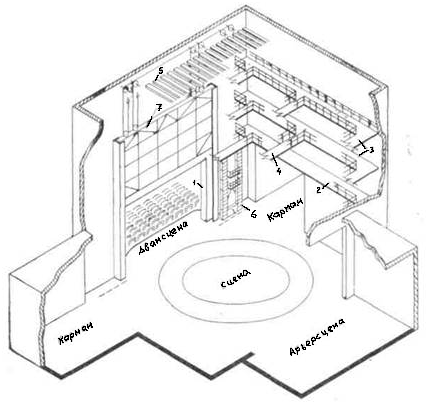
Figure 1. Arrangement of the box scene: 1 - building portal; 2 - lighting gallery; 3 - working gallery; 4—transitional bridge; 5 - grate; 6 - portal tower; 7 - fire-resistant curtain.
The stage communicates with the proscenium through a portal opening. The architectural arch framing this opening is called the stage portal. And the space enclosed inside the portal arch is the mirror of the stage. In theaters of the classical type, the mirror of the stage is somewhat smaller than the size of the portal, since it is cut off from above with a special curb - harlequin. Harlequin serves to camouflage the soles of the fire-resistant and the design of the road intermission curtains. In modern stage solutions, the harlequin, as a rule, is absent.
Special backstage and abutments located behind the portal arch can change the size of the stage opening, forming the so-called working stage mirror or working portal.
On the sides of the stage are additional reserve areas, called pockets. In contrast to the side spaces of the stage, the pockets are located outside the stage box and therefore have a reduced height, approximately equal to the height of the portal. The pockets are used for preparing decorations assembled on rolling platforms-furks. Since the most actively played area is the first plans of the stage, the pocket rooms are placed in this area.
The rear stage, or otherwise the back stage, is, like the pockets, a separate enclosed space adjacent to the back of the main stage.
Basic design requirements
In buildings of cultural and entertainment institutions, water fire extinguishing should be provided:
- in cinemas and clubs with stages with an auditorium capacity of up to 700 seats - fire hydrants; more than 700 places in the presence of grates - fire hydrants and deluge installations;
- in clubs with stages measuring 12.5 × 7.5 m; 15×7.5 m; 18 × 9 m and 21 × 12 m with a capacity of the auditorium up to 700 seats - fire hydrants and deluge installations;
- in clubs with stages measuring 18x9 and 21x12 m with an auditorium capacity of more than 700 seats, with stages 18x12 and 21x15 m, regardless of capacity, as well as in theaters - fire hydrants, deluge and sprinkler installations;
- in demonstration complexes of theaters with a capacity of 600 seats or more with scenes of panoramic, tripartite and central types - fire extinguishing installations
- Fire water supply in the buildings of libraries and archives should be provided for with a building volume of 7500 m3 or more. Water consumption rates and the number of jets for internal fire extinguishing should be taken according to SP30.13330
- In buildings for sports purposes, the irrigation intensity when using sprinkler installations should be taken as 0.08 l / s per 1 m2 based on the calculation of simultaneous irrigation of an area up to 120 m2 with a system operation time of 30 minutes.
The main problem of water fire extinguishing theaters, cinemas
After you complete all the necessary calculations, you will receive some calculated figure (required head and flow). For theaters and cinemas, as a rule, these are very large values of the order of 400 m3 / h and above with a head of 50 m or more.
In rare cases, city water supply can provide these parameters. It is usually necessary to design a fire extinguishing pumping station. According to RF regulations, we can install one working and one standby pump.
For example, consider a pump schedule that was selected for the following parameters: flow rate 489 m3 / h, head 70m.
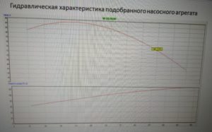
The pump is perfectly matched to the calculated parameters.
Just pay attention to the graph that the pump operates in the range of 55 m3 / h.
During the construction of the theater "X" this pump was installed. The AUPT system has been installed and is ready for operation. But when they began to hand over the object of inspection, the system did not start. What happened? When the object was handed over, a fire valve was opened with a flow rate of 2.5 l / s, the pressure in the network dropped, the pump started, began to vibrate and turned off after about 30 seconds. To hand over this theater, it was necessary to install a frequency converter on these pumps and provide a special cabinet. As a result, the cost of the system turned out to be extremely expensive. In addition, not all manufacturers dare certified fire cabinets for pumps with a frequency converter.
Any other facility with high firefighting costs can have a similar problem. At the beginning of the development of a fire, as a rule, only a fire hydrant and a few sprinklers start working. If the fire has not been eliminated and continues to develop, then after some time all the calculated sprinklers and drenchers are revealed. Those. in the initial stage of a fire, when installing one working pump with a large capacity, we will not put the water fire extinguishing system into operation, because the pump does not work at low flow rates.
To avoid such problems, it is better to install a pumping group of several working pumps with cascade connection. See chart below.
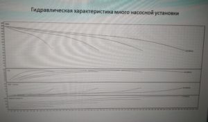
It can be seen from the graph that we cover the entire range of flow rates from 0 and more m3/h, i.e. the pumping unit provides protection against fire from the beginning of its development, when the water flow has not yet reached the design parameters.
At the same time, this scheme has several positive aspects:
- no water hammer occurs in the AUPT system
- power outages are reduced (becausewe have pumps with lower power are switched on sequentially)
- cheaper to replace a broken pump from a pumping group
- we provide work in the system from the beginning of the development of a fire (at a flow rate of 2.5-5 l / s)
With a combined AUPT system with fire hydrants, it is imperative to install diaphragms in front of the fire hydrants to reduce pressure in front of the PC (pressure should be no more than 40m)
Pumping units for fire extinguishing with a frequency converter have also appeared on the modern market (Plazma-T LLC)
You will find the rest of the requirements for the AUPT system for theaters in Appendix L to SP 118.13330.2012.
References: SP 118.13330.2012 "Public buildings and structures" appendix L. "Requirements for the internal fire water supply of buildings of cultural and entertainment institutions, libraries, archives and sports facilities."
Estimated pressure for internal fire extinguishing
In cases where the pressure in the external network is insufficient to ensure the design operation of fire fighting devices, it should be provided for the installation of pumps, the start-up of which should be designed:
- remote from buttons at fire hydrants - in the absence of sprinkler and deluge installations of devices;
- automatic - in the presence of sprinkler and deluge installations, with remote duplication (for start-up and installation) from the premises of the fire post and pumping station
The required pressure is determined by hydraulic calculation.
Free head for hydraulic calculation is determined depending on the dictating point:
- for fire hydrants, free pressure should be provided so that the resulting compact jet irrigates the highest part of the design room. The pressure of the fire hydrants on the floor of the stage should ensure the production of compact jets with a height exceeding by 2 m the distance from the tablet to the grate flooring.
- for the most remote and high-lying sprinkler, the free head must be at least 500 GPa (5 m w.c.)
Similar
| Reference manual for SNP design of retaining walls and basement wallsAnd the Design and Experimental Institute of Industrial Buildings and Structures (TsNIIpromzdaniy) of the State Construction of the USSR | Reference manual for SNiPCentral Research Institute of Building Structures. V. A. Kucherenko (Tsniisk named after V. A. Kucherenko) State Construction… | ||
| Reference manual for SNiPRecommended for publication by the section of the Scientific and Technical Council of the Institute of Public Buildings of the Ministry of Construction of Russia (former TsNIIEP of educational buildings ... | Reference manual for SNP heating and ventilation of residential buildingsCentral Scientific Research and Design and Experimental Institute of Engineering Equipment of Cities, Residential and Public… | ||
| A guide to the design of residential buildings. Issue. 3 (to SNIP 08. 01-85) floors 1If there is a technical floor between the residential part of the house and built-in noisy rooms, a self-supporting ceiling is not required. Soundproofing… | Manual for the organization of high-speed construction of roads and airfields using sets of machines of the ds-100 type (in development of SNiP 01. 01-85, SNiP 06. 03-85, SNiP 06. 06-88)On the organization of high-speed construction of roads and airfields using sets of machines of the ds-100 type (in development ... | ||
| Documentation1. / (to SNiP 2.05.07-85) Design of roads ind. enterprises.doc | Standard regulation on the procedure for issuing initial data and technical specifications for design, approval of construction documentation, as well as payment for these servicesSp 11-101-95, SNiP 11-01-95, rds 11-201-95 and “Reference book of basic prices for design work for construction” | ||
| Leased enterprise promstroyproekt allowance 91 to SNiP 04. 05-91 Fire-resistant air ductsRecommended for publication by the decision of the section of the Technical Council of the leased enterprise Promstroyproekt | "Fire safety of buildings and structures" mds 21 98 Moscow 1998 udk 699. 81 (083. 74) Prevention of the spread of fire.Manual for SNiP 21-01-97 "Fire safety of buildings and structures"Central Research and Design and Experimental Institute of Industrial Buildings and Structures JSC "TsNIIPROMZDANII" | ||
| Decree of 30.11.2012 No. 439-p On approval of the RegulationsRussian Federation, Federal Law of 06.10.2003 No. No. 131-FZ "On the general principles of organizing local self-government in the Russian ... |
Documentation