Operating modes of the hydraulic separator
The main task of this design is the hydraulic separation of the boiler and consumer circuits. After such a separation, the system can operate in different modes when:
- boiler consumption = consumer consumption;
- boiler flow
- boiler flow>consumer flow.
Some consider this flexibility to be one of the benefits of using a water heater for home heating. In fact, of all the options listed, only one is working. Let's consider why this is so.
Q boiler = Q consumers
Of course, the equality of the flow rates of the two circuits is an ideal situation, however, in practice, the implementation of such a regime is impossible. Even if the resistance of the circuits and the performance of the pumps are selected in such a way as to equalize the flow, when one of the consumers or, for example, the thermal head of the radiator is turned on, all equality will come to naught.
Q boiler
This mode, when the flow rate of the heater is less than what consumers require, is quite possible, but it should not be allowed in any case. To understand why such a situation is dangerous, we will analyze the principle of operation of the heating hydraulic arrow in a similar mode.
Let's assume that the boiler is capable of delivering 30 liters of coolant per minute, while the heating system requires 90 liters / min. In this case, the missing flow rate, namely 60 l / min, the system will replenish due to the reverse flow of the coolant, the temperature of which is approximately 20 degrees lower. Thus, water with a lower temperature will enter the consumer circuit, which forces it to increase fuel consumption and heat it up to higher temperature parameters.
A similar mode of operation of the hydraulic separator in the heating system is noted by some "specialists" as an advantage. Like, in this case, it becomes possible to use a cheaper boiler with a lower flow rate. As we managed to find out, this approach is fundamentally wrong, since it can lead to excessive fuel consumption and, even worse, failure of the heater.
Q boiler >Q consumers
The only correct operation of the low loss header is to use the boiler circuit with a slightly higher flow rate than the consumer circuit requires. In this case, the excess coolant is returned to the boiler through the return pipe, heating it. This is necessary in order to prevent thermal shock in the transitional mode, when the “cold” consumer (guest house, pool, basement) is turned on. Simply put, so that the cold return flow does not harm the boiler, it is heated by a heated coolant.
What is a hydraulic arrow in a heating system device and diagram
The design of the water gun is extremely simple. This is a piece of a pipe of rectangular or circular cross section, which has four outlets - two from the side of the boiler circuit and two from the side of consumers. Such an element can be placed both horizontally and vertically. Although the second option is more common, since in this case it is easier to install an air vent and a valve to remove the sludge that accumulates in the lower part of the structure.
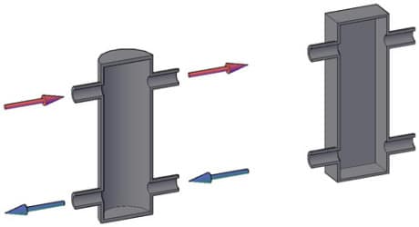
Sectional diagram of a hydraulic arrow for heating systems
Some manufacturers install two grids inside the hydraulic separator. One serves for air separation and the other for sludge separation. Although most often such a product is completely empty, since during operation the grids quickly become clogged and lose their effectiveness.
A hydraulic arrow is installed to break the connection line between the boiler and the collector, which divides the coolant flow between consumers.Sometimes the hydraulic separator and manifold are assembled in one housing. This simplifies installation and makes the overall design more compact.
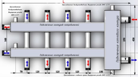
An example of a scheme for manufacturing a hydraulic arrow with a collector in one housing
What is calculated
This procedure is performed for the following utility operating parameters.
- Fluid flow in individual segments of the water supply.
- The flow rate of the working medium in pipes.
- The optimal diameter of the water supply, which provides an acceptable pressure drop.
Consider the methodology for calculating these indicators in detail.
Water consumption
Data on the standard water consumption of individual plumbing fixtures are indicated in the appendix to SNiP 2.04.01-85. This document regulates the construction of sewer networks and internal water supply systems. Below is part of the relevant table.
Table 1
If you intend to use several devices at the same time, the consumption is summed up. So, in the case when the shower cubicle on the first floor is working with the simultaneous use of the toilet on the second floor, it is logical to add up the volume of water consumption by both consumers - 0.12 + 0.10 \u003d 0.22 liters / second.
The water pressure in the future water supply system depends on the correctness of the calculations.
Important! The following norm applies to fire water pipelines: for one jet, it must provide a flow rate of at least 2.5 liters / sec. It is quite clear that during firefighting, the number of jets from one fire hydrant is determined by the area and type of building.
For ease of reference, information on this issue is also placed in tabular form.
It is quite clear that during firefighting, the number of jets from one fire hydrant is determined by the area and type of building. For ease of reference, information on this issue is also placed in tabular form.
table 2
Selection of a distribution manifold
The main rule is that the diameter of the collector should in no case be less than the size of the supply pipe. The larger the diameter of the distribution “comb”, the better for pressure uniformity at the points of water and / or coolant dispensing.
Incorrect selection of the “comb” (see recommendations above), for example, for plumbing, can cause jumps in flow on different devices (see Fig. 2) and cause imbalance, for example, on a mixer.
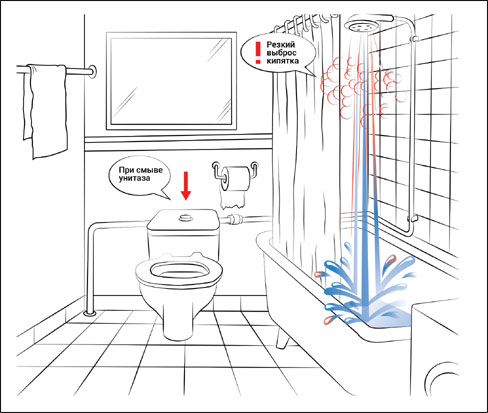 Rice. 2. The result of incorrect selection of collectors for cold and hot water supply
If control valves are not installed on the apartment inlet of hot and cold water, forcibly stabilizing the pressure in the “comb”, then it is especially important for apartment collectors to follow the connection sequence rules. It is necessary to connect devices, the uneven flow of which has little effect on the performance or comfort of the water supply, as “downstream” as possible along the water flow in the “comb”
The water heater should be connected first, then the faucets, followed by the washing machine and dishwashers (making sure that the “no water” shut-off valve is set to a pressure lower than the drop caused by the change in water intake), and at the very end of the collector, the drain pipe ( see Fig. 3).
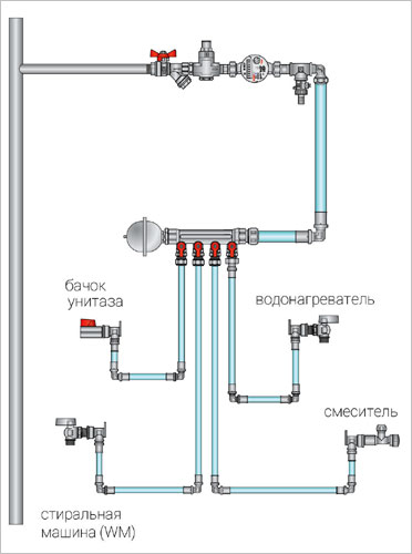 Rice. 3 Example of connecting an apartment cold water distribution manifold
Common collector calculation
The key mode of operation is characterized by the fact that the transistor is in one of two states: fully open (saturation mode), or fully closed (cutoff state).

Consider an example where the load is a contactor of the KNE030 type for a voltage of 27V with a coil with a resistance of 150 ohms. We will neglect the inductive nature of the coil in this example, assuming that the relay will be turned on once and for a long time.
We calculate the collector current:
Ik \u003d ( Ucc - U canas) / R n , where
Ik - collector current
Ucc - supply voltage (27V)
U kenas is the saturation voltage of a bipolar transistor (typically from 0.2 to 0.8V, although it can vary significantly for different transistors), in our case we will take 0.4V
R n - load resistance (150 Ohm)
Ik = (27-0.4)/150 = 0.18A = 180mA
In practice, for reasons of reliability, elements must always be chosen with a margin. Let's take a factor of 1.5
Thus, you need a transistor with a permissible collector current of at least 1.5 * 0.18 = 0.27A and a maximum collector-emitter voltage of at least 1.5 * 27 = 40V.
We open a guide to bipolar transistors. According to the specified parameters, KT815A is suitable ( Ik max \u003d 1.5A U ke \u003d 40V)
The next step is to calculate the base current that needs to be created in order to provide a collector current of 0.18A.
As you know, the collector current is related to the base current by the ratio
Ik \u003d I b * h 21e,
where h 21e is the static current transfer coefficient.
In the absence of additional data, you can take the tabular guaranteed minimum value for KT815A (40). But for KT815 there is a graph of the dependence of h 21e on the emitter current. In our case, the emitter current is 180mA, this value corresponds to h 21e = 60. The difference is small, but for the purity of the experiment, let's take graphical data.
To calculate the base resistor R 1, we look at the second graph, which shows the dependence of the base-emitter saturation voltage (U banas) on the collector current. With a collector current of 180mA, the base saturation voltage will be 0.78V (In the absence of such a graph, we can use the assumption that the I–V characteristic of the base-emitter junction is similar to the I–V characteristic of the diode and, in the range of operating currents, the base-emitter voltage is in the range of 0.6-0.8 V)
Therefore, the resistance of the resistor R 1 should be equal to:
R 1 \u003d (U in-U benas) / I b \u003d (5-0.78) / 0.003 \u003d 1407 Ohm \u003d 1.407 kOhm.
From the standard series of resistances, select the closest one down (1.3 kOhm)
If a shunt resistor is connected to the base (introduced to turn off the transistor faster or to increase noise immunity), it must be taken into account that part of the input current will go into this resistor, and then the formula will take the form:
R 1 \u003d ( U in - U benas) / ( I b + IR2) \u003d ( U in- U benas) / ( I b + U benas / R 2)
So, if R 2 \u003d 1 kOhm, then
R 1 \u003d (5-0.78) / (0.003 + 0.78 / 1000) \u003d 1116 Ohm \u003d 1.1 kOhm
We calculate the power loss on the transistor:
P = Ik * U canas
We take U kenas from the graph: at 180mA it is 0.07V
P = 0.07*0.18= 0.013W
The power is ridiculous, the radiator is not required.
trzrus.ru
Difficulties in choosing the diameter of heating pipes
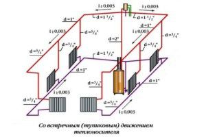
Heating scheme indicating the diameter of the pipes
It would seem that choosing the diameter of pipes for heating a private house is not a difficult task. They should only ensure the delivery of the coolant from the source of its heating to the heat supply devices - radiators to batteries.
But in practice, an incorrectly selected diameter of the heating manifold or supply pipe can lead to a significant deterioration in the operation of the entire system. This is due to the processes that occur during the movement of water along the highways. To do this, you need to know the basics of physics and hydrodynamics. In order not to go into the jungle of precise calculations, you can determine the main characteristics of heating, which directly depend on the cross section of pipelines:
- The speed of the coolant. It affects not only the increase in noise during the operation of heat supply, but is also needed for optimal distribution of heat among heating devices. Simply, the water should not have time to cool to a minimum level when it reaches the last radiator in the system;
- Heat carrier volume. So, the diameter of pipes with natural circulation of heating should be large in order to reduce losses due to fluid friction on the inner surface of the line. However, along with this, the volume of the coolant increases, which entails an increase in the cost of heating it;
- hydraulic losses. If different diameters of plastic pipes for heating are used in the system, then a pressure difference will inevitably occur at their junction, which will lead to an increase in hydraulic losses.
How to choose the diameter of the heating pipe so that, upon installation, you do not have to redo the entire heat supply system due to extremely low efficiency? First of all, you should perform the correct calculation of the section of the highways. To do this, it is recommended to use special programs and, if desired, check the result yourself manually.
At the junction, the diameters of the polypropylene pipes for heating are reduced due to the surfacing. The reduction in the cross section depends on the degree of heating during soldering and compliance with the installation technology.
Flow rate
Suppose that we are faced with the task of calculating a dead-end water supply network for a given peak flow through it. The purpose of the calculations is to determine the diameter at which an acceptable flow velocity through the pipeline will be ensured (according to SNiP - 0.7 - 1.5 m / s).
Calculations are also required to select the pipe diameter.
We apply formulas. The size of the pipeline is linked to the flow rate of water and its flow rate by such formulas:
S is the cross-sectional area of the pipe. Unit of measurement - square meter; π is a known irrational number; R is the radius of the inner diameter of the pipe.
The unit of measurement is the same square meters.
On a note! For cast iron and steel pipes, the radius is usually equated to half of their nominal bore (DN). Most plastic tubing has a nominal outside diameter one step larger than the inside diameter. For example, a polypropylene pipe with an internal section of 32 mm has an outer diameter of 40 mm.
The next formula looks like this:
W - water consumption in cubic meters; V – water flow rate (m/s); S is the cross-sectional area (square meters).
Example. Let's calculate the pipeline of the fire extinguishing system for one jet, the water flow in which is 3.5 liters per second. In the SI system, the value of this indicator will be as follows: 3.5 l / s = 0.0035 m3 / s. Such a flow rate per jet is normalized for extinguishing a fire inside warehouse and industrial buildings with a volume of 200 to 400 cubic meters and a height of up to 50 meters.
For polymer pipes, the outer diameter can be one step larger than the inner
First, we take the second formula and calculate the minimum cross-sectional area. If the speed is 3 m/s, this figure is
S=W/V=0.0035/3= 0.0012 m2
Then the radius of the inner section of the pipe will be as follows:
Thus, the internal diameter of the pipeline must be equal to at least
Din. \u003d 2R \u003d 0.038 m \u003d 3.8 centimeters.
If the calculation result is an intermediate value between the standard tubular dimensions, rounding up is performed. That is, in this case, a standard steel pipe with DN = 40 mm is suitable.
How easy it is to find out the diameter. In order to perform a quick calculation, you can use another table that directly links the water flow through the pipeline with its nominal diameter. It is presented below.
Table 3
head loss
The calculation of the pressure loss in a pipeline section of known length is quite simple. But here it is necessary to use a fair amount of variables. You can find their values in reference books. And the formula looks like this:
P is the head loss in meters of water column. This characteristic is applicable due to the fact that the pressure of water in its flow changes; b is the hydraulic slope of the pipeline; L is the length of the pipeline in meters; K is a special coefficient. This setting depends on the purpose of the network.
The pressure loss is affected by the presence of shut-off valves and bends in the pipeline
This formula is greatly simplified. In practice, pressure drops are caused by valves and bends in the pipeline. You can familiarize yourself with the figures reflecting this phenomenon in fittings by studying the following table.
Table 4
Some elements of the above formula need to be commented on. With the coefficient, everything is simple. Its values can be found in SNiP No. 2.04.01-85.
Table 5
As for the concept of "hydraulic slope", everything is much more complicated here.
Important! This characteristic displays the resistance provided by the pipe to the movement of water. Hydraulic slope - the value of the derivative of the following parameters:
Hydraulic slope - the value of the derivative of the following parameters:
- flow rate. The dependence is directly proportional, that is, the hydraulic resistance is higher, the faster the flow moves;
- pipe diameter.Here, the dependence is already inversely proportional: the hydraulic resistance increases with a decrease in the cross section of the engineering communication branch;
- wall roughness. This indicator, in turn, depends on the material of the pipe (the surface of HDPE or polypropylene is smoother than that of steel). In some cases, the age of the water pipes is an important factor. Lime deposits and rust that form over time increase the roughness of the surface of their walls.
In old pipes, the hydraulic resistance increases, because due to the overgrowth of the inner walls of the pipes, their clearance narrows.
Graphical method for calculating the hot water supply system
Since there is little precision required to determine the amount of equipment that needs to be purchased to organize solar water heating and supply it to the house, many manufacturers and suppliers of hot water systems have developed their own calculation methods, translating them into simple graphs.
According to such schedules, any potential buyer can independently determine their needs for certain components of the water heating system. Below is one such chart. To determine the composition of the equipment, you must perform several sequential steps.
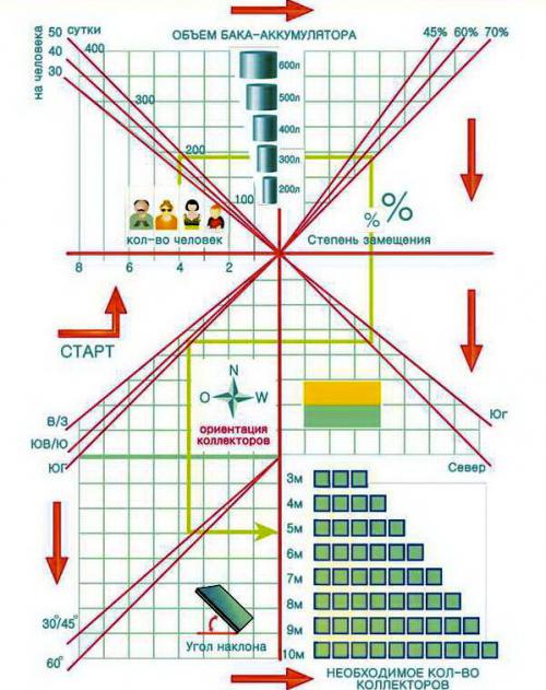 Graphical definition of the composition of equipment for hot water supply
- Determine the number of regular customers.
- Set the approximate amount of water used.
- Based on these data, determine the recommended volume of the boiler.
- Set the optimal degree of substitution of daily heat demand for solar energy.
- Roughly select ("North" - "South") your location.
- Determine the intended orientation of the helium collectors.
- Set the angle of the collectors in relation to the horizon.
After completing these steps, you will receive an approximate composition of the equipment that is necessary to meet your needs for hot water, namely the volume of the boiler, the number of collectors. And it’s up to you to decide how exactly to use this equipment - as the main or auxiliary hot water supply system.
Knowing the composition of the DHW system, you can easily calculate the cost of all components, as well as approximately calculate the payback period for this equipment.
solarb.ru
Advantages of the scheme
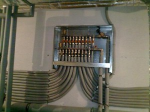 Country house heating systems
The advantages of such a coolant supply scheme are ease of use. The operation of the system and the control of heating devices are as comfortable as possible:
- The temperature of each circuit element can be controlled centrally. Being near the collector, the homeowner can limit the supply of coolant to any register or turn it off altogether. It is convenient to control the temperature in each room.
- Each branch that departs from the collector feeds only one radiator. Therefore, pipes of small diameter can be used for laying highways. In most cases, the highways are laid in a concrete base. This heats up the floor.
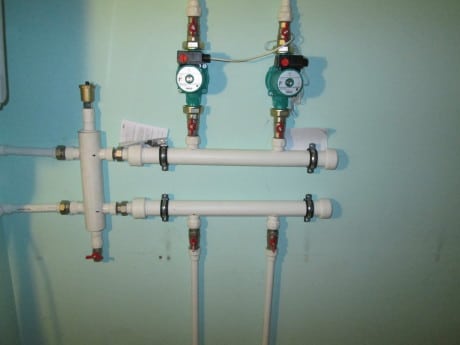
- If necessary, using a collector, it is easy to form several independent circuits with different temperature indicators. For this, it is preferable to use the so-called hydraulic gun - a type of collector. It is characterized by a large internal diameter of the pipe.
The installation of this variant of collector heating is somewhat unusual. It is planned to create short circuits between the hot water supply and the return lines.
The water heated by the boiler constantly circulates along the contours of the hydraulic arrow. At the same time, hot coolant can be taken at different distances from the collector, creating a temperature difference even in a single room. This option can be used for complex heating of the house - using traditional systems and "warm floors".
Hydraulic calculation of pipelines of heating systems using programs
Calculating the heating of a private house is a rather complicated procedure. However, special programs make it much easier. Today, there is a choice of several online services of this type. The output is the following data:
- the required diameter of the pipeline line;
- a certain valve used for balancing;
- dimensions of heating elements;
- values of differential pressure sensors;
- control parameters of thermostatic valves;
- numeric settings of the control parts.
Program "Oventrop co" for the selection of polypropylene pipes. Before starting it, it is necessary to determine the required elements of equipment and set the settings. At the end of the calculations, the user receives several options for implementing the heating system. Changes are made iteratively.
Calculation of the heating network allows you to choose the right pipes and find out the flow rate of the coolant
This hydraulic calculation software allows you to select pipe elements of the line of the desired diameter and determine the flow rate of the coolant. It is a reliable assistant in the calculation of both single-tube and two-tube designs. Ease of use is one of the main advantages of Oventrop co. The set of this program includes ready-made blocks and catalogs of materials.
HERZ CO program: calculation taking into account the collector. This software is freely available. It allows you to make calculations regardless of the number of pipes. HERZ CO helps to create projects for renovated and new buildings.
Note! There is one caveat here: a glycol mixture is used to create structures. The program is also focused on the calculation of one- and two-pipe heating systems
With its help, the action of a thermostatic valve is taken into account, as well as pressure losses in heating devices and an indicator of resistance to the flow of coolant are determined.
The program is also focused on the calculation of one- and two-pipe heating systems. With its help, the action of a thermostatic valve is taken into account, as well as pressure losses in heating devices and an indicator of resistance to the flow of coolant are determined.
The calculation results are displayed in graphical and schematic form. HERZ CO has a help function. The program has a module that performs the function of searching and localizing errors. The software package contains a catalog of data on heating devices and fittings.
Software product Instal-Therm HCR. Radiators and surface heating can be calculated using this software. Its package includes the Tece module, which contains subroutines for designing water supply systems of various types, scanning drawings and calculating heat losses. The program is equipped with various catalogs that contain fittings, radiators, thermal insulation and a variety of fittings.
The length of the pipeline is important for calculations
Computer program "TRANSIT". This software package allows for multi-variant hydraulic calculation of oil pipelines, in which there are intermediate oil pumping stations (hereinafter referred to as OPS). The initial data are:
- absolute roughness of pipes, pressure at the end of the line and its length;
- elasticity and kinematic viscosity of saturated oil vapors and its density;
- brand and number of pumps switched on both at the head station and at intermediate PSs;
- layout of pipes according to the size of the diameter;
- pipeline profile.
The result of the calculation is presented in the form of data on the characteristics of gravity sections of the highway and on the pumping flow rate. In addition, the user is given a table showing the pressure value before and after any of the pumps.
In conclusion, it must be said that the simplest calculation methods were given above. Professionals use much more complex schemes.
How much will it cost to install a hydraulic arrow with a collector
We examined what it is and why a hydraulic arrow is needed in heating. Now let's try to figure out how much it will cost to install such a structure together with a collector and when it is necessary to resort to such a service.
The hydraulic separator with the manifold itself is an expensive component. In addition, their installation entails a number of additional costs. Here are the average prices that currently exist on the market for these services:
- Hydraulic separator (factory production) - 200 euros;
- Collector (factory) - 300 euros;
- Piping (faucets, fittings) - 100 euros;
- Controller (required to control pumps outside the jurisdiction of the boiler) - 400 euros;
- Installation services (25% of the cost of materials) - 250 euros.
In total, it turns out 1250 euros - a pretty decent amount. Therefore, before installing a hydraulic gun, you need to make sure that it is really necessary. If the specialist performing the installation is not engaged, then he will recommend the installation of a separator only if there are three or more heating circuits (excluding the boiler).
Of course, you can use a hydraulic arrow with a handicraft collector, the manufacturing scheme of which will not differ in any way from the factory version. However, the quality of the material and welds is unlikely to meet technical standards. By saving on materials, as a result, you can significantly reduce the reliability of the system. And it’s good if the breakdown does not occur at the height of the heating season.
Polypropylene hydraulic separator - a simple but unreliable option
What conclusion can be drawn from this article? Firstly, the versatility of the hydraulic gun, which is so often talked about, is too exaggerated. It must be used only in one case - to coordinate the operation of several pumps with different capacities. Secondly, for reliable operation of the system, it is better to use a separator with a factory-made collector, and entrust the installation to specialists, whose goal is not to enrich at the expense of customers, but to actually optimize the operation of autonomous heating.