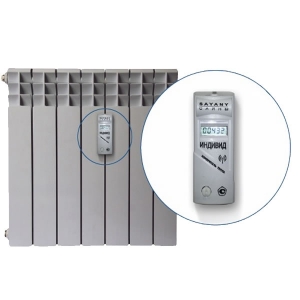
Popular instrument models
 Meet all requirements for performance, accuracy of control devices Techem"
. The brand's products also have good reviews from specialists. "Pulsar"
. Among the advantages of the units of this brand are the removal of indicators without visiting the apartment, a program that reads indicators, simple setup and operation, and protection from external heating.
Successfully used and heat distributor Decast"
. It can be mounted with vertical and horizontal wiring, it functions perfectly in apartments, cottages, offices, administrative and other buildings. Among the advantages of the model is versatility, it fits most models of heating appliances.
Heat metering with apartment distributors
Heat distributors are still not widely used in our country, although in Europe they have been used on an industrial scale since the 70s, and the number of installed heat distributor devices amounts to tens of millions. We do not yet produce these devices, although we already have experience in their use.
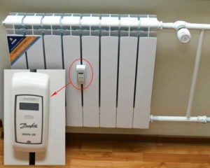
The principle of operation of distributors
The photo shows a thermostatic regulator and a radiator heat distributor installed in an apartment. The distributor measures the temperature of the radiator surface at one specific point every 3-4 minutes and records the temperature difference between the surface of the radiator and the air in the room in a non-volatile memory.
As a result, the readings of these heat meters correspond to the amount of heat given off by the radiator over the past period, measured in conventional units.
It is conditional, the readings of the heat distributor during recalculation are multiplied by the radiator coefficient corresponding to the given type and size of the heater.
At the same temperature on the surface of a large and small radiator and at the same temperature in the room, the readings of the distributors will be the same, but will a large heater give off more heat? To take this situation into account, the radiator coefficient is used. Each manufacturer has tables of radiator coefficients for their devices for all types of manufactured radiators. Tables of radiator coefficients are included in computer programs for recalculating payments, and the coefficients are automatically taken into account in the calculation.
But what about our homemade radiators or battery assemblies, when the residents themselves add sections to the existing radiator, while some of them practically do not heat. There is only one conclusion, you will have to get rid of homemade products.
The cost of a heat distributor and payment for heat
The cost of a heat distributor is about 10 times less than the cost of an apartment heat meter. Distributors are easily installed on any type of heating devices. This is the main advantage. Due to this, the cost of a set of devices for an apartment is acceptable even if there are several risers in the apartment.
Heat distributors are suitable for all heating systems
Calculation of payment for heating according to the readings of the heat distributors is the distribution of the total amount paid to the heat supplier between individual apartments in proportion to the readings of the radiator distributors.
At the same time, apartment residents monthly, throughout the year, make payments at fixed, pre-calculated and approved rates, and settlements with the heat supplier are made according to the indications of the general house heat meter.
Once or twice a year, readings are taken in apartments, and the total amount is distributed according to the readings received.For each tenant, a balance is drawn between the amount of his payments at provisional rates and his estimated payment. The amount received is used to offset payments for heating for the next year.
Finally, let's compare the costs of installing radiator thermostats and heat distributors.
Equipment and costs, Price per piece (at the rate of $ 1 - 60 rubles)
Considered:
- Distribution sensor for individual metering INDIV-3 with visual reading from the LCD display
- Sensor-distributor for individual accounting INDIV-3R with remote wireless data transmission (radio)
- Installing a thermostat and measuring sensor
- Annual apartment settlement services
In the table, the costs for the installation of radiator thermostats and heat distributors
Calibration interval of heat distributors is 10 years. Apartment heat meters - 5 years.
The payback period for installing heat distributors and radiator thermostats for a two-room apartment is 1 year, with a service life of a thermostat of 30 years, and a heat distributor of 10 years. For economical residents, this period will be even shorter.
Remember the basic rules for organizing apartment accounting using heat distributors:
- thermostatic regulators must be installed on heating appliances.
- at least 75% of the heated premises must be equipped with thermostats and heat distributors in the building.
- the actual cost of thermal energy for heating a residential building should be made by a common house heat meter.
- in the housing organization, recalculations of payments for residents should be organized according to the readings of common house and apartment metering devices.
Paramonov Yu.O. LLC enterprise "Energostrom" 2017.
Read more - Equipment necessary for apartment accounting. What else to read on the topic:
Place and method of mounting the collector
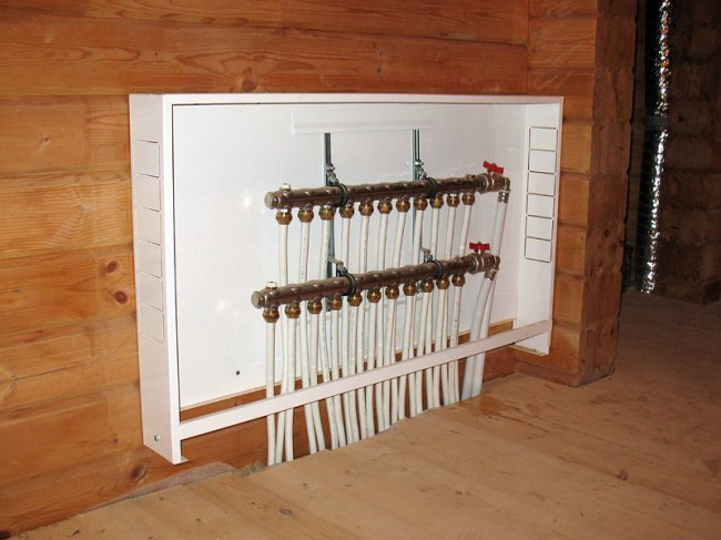
Cabinet for heating manifold. Click on the photo to enlarge.
To install the heating collector, specially prepared niches are used slightly above the floor level. This point should be taken into account at the design stage of the house. If modification of the existing heating system is required, the distribution block can be placed in any room. When determining the optimal location for the collector, it is necessary to choose rooms with normal humidity. This requirement is met by such premises as:
- pantry;
- corridor;
- dressing room, etc.
A special cabinet is used so that the appearance of the heating collector does not spoil the interior of the room. A cabinet with a lock will protect the operation of the heating system from the intervention of children. Buying a cabinet is not difficult, different models are produced by manufacturers of valves. They are metal boxes with doors, holes for pipes are made in the end walls. If the collector group does not spoil the look of the room, the structure can simply be attached to the wall in an open form.
Payment for heat during the operation of the distributor in the apartment
There is two options
the principle of calculating the amount of payment for heating in an apartment.
- According to the first option, the readings of the collective meter are also taken into account, but once a year a recalculation should be performed taking into account the indicators of the cost allocator in the apartment. In the text Government Resolution No. 354
there is an algorithm for calculating payment in those houses where heat meters are installed in most of the apartments. - According to the second option, payment is charged according to the readings of the heat meter, but these indicators should be in kWh.
The management company serving the house must accept indicators from consumers, which can be transmitted through the service of the Internet resource, by phone.
At the same time, employees of the management company have the right to check the operation of metering devices, the accuracy of the indicators that the consumer informs about.
Types of collectors in heating systems
The model range of products according to the specifics of functioning is divided into 3 types - solar and distribution collectors, hydraulic arrows. The second position has the largest coverage of consumers.
Solar collectors
Designed primarily for solving economic problems, in the southern regions they can be fearlessly assigned to all the processes associated with heating. In mid-latitudes with insufficient solar radiation, such collectors are used to provide hot water during periods when the heating boiler is idle.
The collector of solar panels consists of registers placed in vacuum tubes, they interact with a closed circuit operating on the basis of a liquid agent. As the agent evaporates, it rises to the heat exchanger and heats the working medium. When cooling, the substance descends, thereby laying the cycle of the process.
Hydraulic arrow - thermohydraulic distributor
 In the photo there is a hydraulic gun with a stainless steel manifold
The hydraulic separator is actively used in complex heating circuits based on several heating circuits; it combines the boiler with radiators, hot water supply, and underfloor heating. Factory models of devices include flow separators, as well as mechanisms that remove air and contaminants from the system.
To optimize heating, it is desirable to provide each circuit with its own pump. A hydraulic arrow is a special category of a collector, it is distinguished by the ability to work with large pipe diameters, it is mounted in a boiler room in a vertical plane.
Distribution manifolds for the heating system
They carry the flow of the working medium directly to the heating devices. Structurally, the product consists of a pair of combs, the first one is necessary to deliver the coolant to the heating points, the second one drains water back to the boiler room. In the end part of each distributor, connections to highways are provided, directly along the body you can see fittings for specific devices, in particular, for underfloor heating circuits, heating batteries.
The arrangement of radiator heating using a distribution manifold, in comparison with traditional 1-2-pipe schemes, is carried out in parallel, and not, as everyone is used to, in series. The coolant, bred in all branches, has the same temperature. The characteristics of each radiator or group within the same circuit can be set in accordance with requests, while you can not be afraid of their mutual influence.
For underfloor heating, the use of combs is the only viable option to ensure smooth operation of the system. If necessary, the collector can be mounted discreetly, disguised with a special cabinet placed in a niche.
Basic models of heat distributors
- Versions INDIV-3 and INDIV-3R. These distributors have one built-in temperature sensor. Such devices use the principle of accumulating the resulting reading over time at a rate that is determined by the output signal of the built-in sensor.
- Versions INDIV-3R2 and INDIV-3RD. These models have 2 temperature sensors (heater surface and ambient air). In the INDIV-3R2 distributor, both sensors are built into the housing. In the NDIV-3RD device, the air temperature sensor is built-in, and the heater surface sensor is remote.
All types of valves allow memorizing and displaying the resulting reading on a pre-set day of the year. The devices are used in internal heating systems.
Any distributor can be installed on:
- Sectional radiator made of cast steel or cast iron.
- Aluminum heating battery.
- Tubular and panel radiators.
- Pipe registers.
- Convectors.
The heat distributor solves the following tasks:
- Accumulation of consumption readings.
- Indication of consumption readings for the previous year.
- Checksum indication for verification.
In addition, the distributor is equipped with a self-test system.
Specifications INDIV-3:
- Design temperature range in heat supply systems: 55-105 degrees Celsius.
- Starting reference temperature: June-August: 40 degrees Celsius, September-May: 30 degrees Celsius.
- Heat distributor power supply: lithium battery.
- Dimensions: 40x76x25 mm.
- Distributor measurement accuracy: complies with European standard EN834.
The role of the collector in heating
When arranging a water pressure unit, it is necessary to adhere to the rule: the total sum of the diameters of all branches should not be greater than the diameter of the supply line.
We apply this law to the heating system, but it will look like this: the outlet fitting of the boiler with a diameter of 1 inch is allowed for use in a two-circuit system with pipes with a diameter of ½ inch.
For a house with a small cubic capacity, which is heated exclusively by radiators, this kind of system is considered productive.
In practice, a private cottage is equipped with a more modernized heating scheme, where additional circuits are equipped:
- underfloor heating system;
- heating of several floors;
- utility rooms, etc.
When a branch is connected, the level of working pressure in the circuits becomes insufficient for high-quality heating of all radiators, respectively, and the comfortable atmosphere mode will be violated.
In this case, for a branched heating main, a balancing unit is equipped using a distribution manifold. Using this method, it is possible to compensate for the cooling of the heated coolant, which is typical of traditional one- and two-pipe schemes.
By means of equipment and valves, the necessary indicators of the coolant temperature for each of the lines are adjusted.
Installing the comb in the heating system
The first task is to check the distribution manifold for tightness of the connections. The installation is implemented according to the design scheme. Depending on the material used to make the main unit, the connection conditions are determined.
The choice of connection technology depends entirely on the modification of the device used.
In addition to holding the level, the following rules must be followed during installation:
- boilers of electric and gas type are connected to the upper or lower nozzles;
- a circulation pump is mounted in the end part of the structure;
- connection of circuits can be carried out at the top or bottom of the comb;
- indirect heating devices and solid fuel boilers must be connected to the distribution group from the side;
- the entire hydraulic separation unit for the underfloor heating system is placed in a protective box - this reduces the risk of damage to the constituent elements of the collector.
At the final stage, it is necessary to make a control start of heating in order to timely identify hidden or obvious shortcomings of the design made.
Additional information on the organization of a radiant heating system using a distribution comb is given in this article.
Heat meters
The system of individual heat billing is widely used in a number of countries, it takes into account the heat consumption of individual consumers, for example, central heating radiators. It consists of a heat distributor and a radiator thermostat. The heat distributor is installed on each radiator in the apartment and records the amount of heat given off by the radiator.
Evaporative heat distributor Exzemper
In an evaporative heat distributor, the heat from the radiator acts on a special liquid in the measuring ampoule, which evaporates depending on the temperature and duration of the heat from the radiator. The hotter the radiator and the farther its heat acts on the ampoule, the more liquid evaporates.
The amount of liquid evaporated indicates how much heat a given radiator uses.
Electronic heat distributor "DOPRIMO"
Doprimo is a modern high-tech electronic device with two built-in temperature sensors - one measures the surface temperature of the radiator on which the distributor is installed, and the second measures the air temperature in the room. The temperature sensors are connected to the electronic unit of the calculator, which determines the temperature difference between the two sensors and integrates the resulting difference over time. The obtained value characterizes the heat input (thermal pressure) from the radiator into the room, measured not in absolute (Gcal, kWh, etc.) but in relative conventional units.
The accumulated values of heat consumption are displayed on the LCD screen built into the body of the device and are available for visual reading.
To set the initial parameters of the heat distributor during installation, change parameters during operation or to read archived data, there are optical inputs on the housing.
Radiator thermostat
A radiator thermostat (thermostat) is an automatic device designed to maintain a predetermined room temperature. It can be installed both in apartments with central heating and in cottages with an individual heating system, as well as in any other premises, regardless of the year the building was built. The purpose of this device is to maintain a comfortable temperature in the room, set by the owner, saving him from unnecessary trouble. The thermostat is installed on the pipe that supplies the coolant to the radiator. Responding to changes in the air temperature in the room, it regulates the flow of hot water passing through the radiator. This reduces or increases the amount of heat given off by the heater. The principle of operation is based on the property of substances to increase their volume when heated and reduce it when cooled. Inside a modern thermostat, or rather, in a small sealed flask with corrugated walls, called a bellows, there is a temperature-sensitive substance (it can be paraffin, liquid or gas). It reacts to any changes in the air temperature in the room. If the temperature drops below that set on the scale, the volume of the substance decreases, and the accordion-like bellows itself contracts and moves the valve stem, increasing the amount of hot water passing through the radiator. At the same time, the air temperature in the room rises. Conversely, when the room air temperature rises above the set temperature, the substance in the bellows increases in volume, moving the valve stem in the other direction. Less water begins to flow into the radiator and the temperature in the room decreases. The radiator thermostat is easily installed on any type of heater, and you can manually select the optimal temperature regime not only for the entire apartment, but also for each room separately.
On which radiators can not put the distributor
Despite the versatility and high functionality of the thermal energy distributor, there are a number of restrictions
to install the distributor.
- The device is not installed on a radiator through which not hot water passes, but water vapor.
- On heat sources located in the floor screed or radiating heat from the ceiling. If a warm floor is installed, a flow meter is used as a metering device - this is a device that allows you to control the flow of coolant in the loops connected to the collector.
- It is impossible to mount counters for the heat of the device on a radiator, in the design of which there is an electric heater or an electric fan.
- On batteries with decorative elements, except when the device will fit snugly against the structure.
How to make a do-it-yourself heating distribution manifold
The product design is based on the number of heating circuits used
It is necessary to take into account the location of the heating boiler, the specifics of the pipes, the features of heating and indirect circuits, plans for a possible increase in their number in the future, heat distribution points
 An example of a do-it-yourself heating distribution manifold
When drawing up a project, it is also necessary to take into account that each circuit has two pipes - for supply and return. It will be necessary to note additional equipment - a drain valve, an expansion tank, a group of thermostats, a filling valve, a make-up valve.
The next stage is spatial modeling. You will have to figure out the specifics of connecting pipes to the collector, usually taps are formed at the ends for indirect heating and connection with a solid fuel boiler, for electric and gas wall-mounted boilers, the pipe cuts from above. All collected information is taken into account when drawing up a collector drawing (graph paper is useful here). Between adjacent nozzles, it is necessary to maintain a distance of 10 cm, as practice shows, a maximum of 20 cm.
The most convenient material for self-assembly of the comb is a pipe profile of square or regular section. To perform marking, it is desirable to prepare a ruler, caliper, core. Using a gas cutter, holes are made into which pipes will be cut in the future. Threaded pipe trims must be inserted into these seats.
The workpieces are fixed by welding - first rough, the second step processes the entire perimeter. Next, you need to equip the resulting body with brackets for hanging the comb on the wall. Joints must be cleaned of rust and scale. The structure is coated with a degreasing compound, paint and varnish are applied successively.
After 2-3 days, when the layers of paint are completely dry, the collector can be mounted on the prepared place and connected to the incoming and outgoing circuits. As a result, an effective tool is formed that can fully coordinate the complex heating system of a private household.
The defining task in the design of an autonomous heating system is the uniform distribution of the heat carrier. This task in the heat supply system is performed by the control and adjustment unit - the distribution manifold.
The uninterrupted operation and reliability of the heating circuit largely depend on the competent choice of the device, high-quality installation and connection. If there is a desire to install a heating distribution manifold with your own hands, then it is necessary to carry out calculations in advance and design the wiring.
We will help you resolve these issues. In the article, we examined the design of the collector group, outlined the pros and cons of a heating system with a comb, described the rules for designing and installing a distribution unit.
The material is supplemented with practical advice on choosing components, assembling and connecting the collector to the heating system.
hydraulic locks.
hydraulic
the lock is called the guide hydraulic apparatus,
flow-through
working fluid in the absence
control action - in one
direction, and if there is a manager
impact in both directions.
Hydraulic locks are widely used in hydraulic drives
for automatic locking of the working
liquids in the cavities of hydraulic motors in
in order to stop their output links
in the given positions.
hydraulic locks
subdivided according to the following criteria:
according to the number of locking elements - one-sided
and bilateral; according to the design of locking
elements - with ball and conical
valves; but the type of control action
- with hydraulic, pneumatic,
electromagnetic and mechanical
management.
constructive
difference between hydraulic locks and non-return valves
is that the former have
elements for
forced opening of the valve
passage of working fluid in one
direction. In the absence of a manager
impact hydraulic locks work like
non-return valves: allow fluid to pass through
only in one direction. So
Thus, a hydraulic lock is a controlled
check valve.
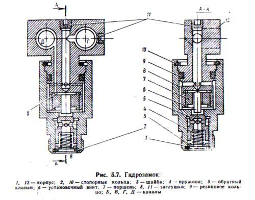
Working
hydraulic lock (Fig. 5.7) as follows.
With spool valve
working fluid from pressure line
is fed into channel G of building 12, further,
overcoming the resistance of the spring 4,
passes through the annular grooves to
valve 5, opens it and through the channel
B enters the piston cavity
corresponding machine cylinder.
The reverse flow of the working fluid is closed
valve 5, therefore, spontaneous
movement of the hydraulic cylinder
load is excluded.
At
supply of working fluid from the pressure
line with the help of a spool in the stock
the cylinder cavity through channels D and
B hydraulic lock acts on the piston
7, which with its set screw 6
opens valve 5. As a result of this
fluid from the piston cavity of the cylinder
through channels C and G of the hydraulic lock goes to
drain into the tank, while the rod moves
inside the cylinder.
V
hydraulic systems of road construction
machines are most widely used
unilateral balanced and unbalanced
hydraulic locks with conical shut-off
element having a conditional passage of 16,
20, 25 and 32 mm.
V
unbalanced one-way hydraulic lock
rod end of the control hydraulic cylinder
connected to the subvalvular cavity (with
internal drainage). In unloaded
unilateral hydraulic locks these cavities
separated and isolated stock
hydraulic cylinder cavity control
connected to a drainage hydro-line (with
separate drain). Parameters
one-way hydraulic locks are given
in table. 5.4.
Are common
intelligence.
hydraulic lines
called devices for
for the passage of the working fluid into
during the operation of the volumetric hydraulic drive.
They are an external system
communications in the form of rigid metal
pipelines, elastic (flexible)
low and high pressure hoses.
V
in accordance with the functions performed
hydraulic lines are divided: into suction
- through which the working fluid moves
to the pump pressure - on which the working
pressurized fluid moves from
pump to distributor, hydraulic motor
or hydraulic accumulator; drain - by
by which the working fluid-moves in
hydraulic tank In addition, there are hydraulic lines
controls, according to which the working fluid
moving towards control devices,
and drainage, through which leaks are diverted
working fluid.
Main
requirements for hydraulic lines are
ensuring-minimum hydraulic
resistance and structural strength.
To do this, the hydraulic lines and channels should be
do as much as possible
section with the least number of local
resistance.
For
pressure hydraulic lines flow rate
working fluid is recommended to choose
5 ... 10 m / s, for suction - 1 ... 2 m / s.