Central quality control of the combined load.
When choosing a chart
regulations focus on
relative load of hot water, depending
on the coefficient μ
μav=
Qguardssrn/
QO’
If
μav =>
0.15, to ensure quality
regulation needs central
regulation to be supplemented by group and
regulation to increase
combined heating load schedule
and gvs.
V
pulse quality for regulation
heating load on the central
heating points use internal
t
heated rooms or t
device simulating th
heated rooms.
Central
regulation of closed systems
heat supply can be taken at
any relative number of subscribers
with both types of load in case
use of system regulators
heating.
Using
flow controllers this regulation
applies only when
at least 75% of residential and public buildings
have hot water installations.
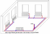
Consider
combined load control
with a closed heat supply scheme with 2x
stepwise sequential heating
water for hot water supply.
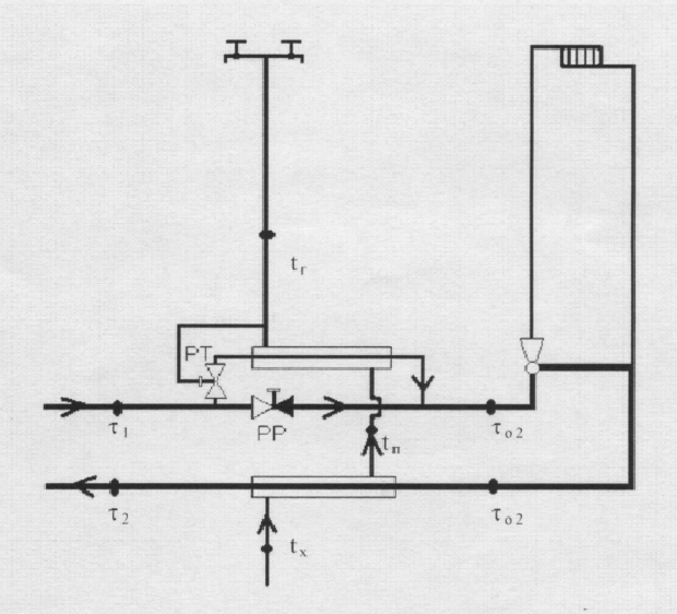
Consumption
network water in the installation under consideration
regulated by the flow regulator PP and
temperature controller RT. PP supports
constant set network flow
water through the elevator nozzle. When
PT valve opens increases
water flow through the top heater
steps, PP is covered for as much
so that the water flow through the elevator nozzle
didn't change.
Advantages:
1.
Alignment of uneven daily
combined load graph due to
use of storage capacity
builds structures.
2.
minimum consumption of network water,
practically = water consumption for heating
3.
reduced t
network water through the use
return water heat for partial
cover the DHW load.
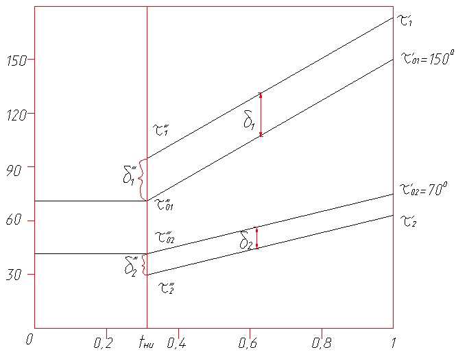
elevated
schedule
central quality regulation
combined load.
basis for it
constructing a regulation schedule
by heating load.
Task
calculation of central regulation
is to determine t
water in the supply and return lines
for various t
outside air.
Initial data
for calculation are:
1)μ
for a typical subscriber; 2) settlement
graph t
for heating; 3) typical daily schedule
for the DHW system.
Temperature
heating control schedule
loads are built according to the equations:
a) change
supply water temperature
highways
 —
—
b) temperature
network water after the heating installation

c) temperature
water after the elevator or after
mixing device
 .
.
Where
 —
—
temperature difference of the heating
installations in the design mode.
 —
—
temperature difference of network water in
heating network in the design mode.
 —
—
water temperature difference in the local or
subscriber installation.
Basic
calculation is carried out according to the balance load
DHW systems
Qguardsb=χb
Qguardssrn
χb
- correction factor for compensation
imbalance of heat for heating,
caused by uneven daily
DHW schedule (if batteries are present)
hot water =1, in the absence of accumulators
hot water for residential and public
buildings = 1.2)
Payment
t
combined load chart
is to determine the differences
t
network water in the heaters of the upper
and lower stage at different values
tn
and Qguardsb
δ1
and δ2 is the difference t
in heating top. and lowersteps, respectively.
At
balance load DHW system total
differential t
constant for any t
outside air.
δ
= ρguardsb(τ01,
- τ02,)
pguardsb=
Qguardsb/
QO’
drop
t
in the lower stage of the DHW heater at
any t
outside air.
δ2=
δ2'''
( ( τ02—
tx)/
( τ02,,,-
th))
δ2'''
- difference t
in the lower stage heater at the point
break th
graphics
δ2'''=
pguardsb(
( t'''P—
tx)/
(tG’-
th))
(τ01’
- τ02’)
pguardsb-
relative coefficient
th
– tcold
water
tp
– t
water at the outlet of the bottom heater
steps.
t'''P
- temperature
water from the lower stage heater
at the temperature break point
with balance sheet
d.h.w. load total temperature difference
in the upper and lower stage heater
constant:
δ
= δ1+δ2=const
δ
= ρguardsb(τ01’-
τ02’)
difference
temperatures in the heater
steps δ1 = δ-δ2
on
the found values of δ1 and δ2 and the known
values τ01’
and τ02’
determine τ1
and τ2:
τ1=
τ01+
δ1
τ2=
τ02—
δ2
then
available with central control
combined heating and hot water load
supply water temperature
mains of the heating network are higher than along
heating schedule, τ1>
τ01,
Therefore, the schedule is called heating.
Rice. 2. Scheme of an individual heating point with a temperature and flow controller pos. 2.11 dependent wiring diagram
Energy savings can only be achieved with proper design, configuration and installation of all elements of the substation.
The experience of ITP installations shows that home heating systems must be clearly described and inspected even before the start of ITP design work. Is it so in practice? In some cases, the preparation is done carelessly, as a result of which the characteristics of the heating point differ from those required. This discrepancy arises from errors that accumulate from the data collection stage until the elements are assembled into a single product. Therefore, when designing, they try to use universal equipment or selection with a "margin", which is not optimal for the control system.
In addition to the ITP components (pump, heat exchanger, shutoff valves and pipelines), a heat flow controller and a programmable logic controller (PLC) play an important role in the operation of the heating point - the central elements of the automatic control system (ACS).
In a sense, combined temperature and flow control valves can be considered a universal solution. Thanks to fittings such as the combi valve, the sizing is limited to the flow calculation only (kg/h), while the differential pressure controller is excluded from the calculation.
The function of maintaining a constant differential pressure is provided by a special design of the combi-valve (Fig. 3). Temperature and flow controllers are successfully used in circuits with dependent and independent connection of consumers to heating networks.
Rice. 3. Design with temperature and flow control
The combi valve has a design with two oppositely located gates: a flow regulator gate and a control valve gate.
The principle of operation is the following. When the control valve shutter is fully open, the flow regulator automatically maintains the specified maximum allowable flow rate Gmax (kg/h). In this case, the calculated resistance of the combi-valve (when it is fully opened) is determined by the sum of pressure losses at the control valve gate and the minimum required pressure loss at the flow regulator of 0.5 bar (50 kPa), which ensures its performance.
The action of the electronic controller (PLC) is aimed at reducing the flow below a predetermined maximum value by acting on the control valve shutter actuator.The flow characteristic of a combi valve is linear, in other words, it is a flow characteristic of a control valve, in which the relative flow is proportional to the relative stroke. Thanks to this fitting, in combination with the ACS system (based on a programmable controller), it is possible to achieve a sufficiently high accuracy of object control with dynamically changing characteristics (especially with external disturbances) of the heating network.
That is why solutions using combined valves manufactured by HERZ (Fig. 4) aroused great interest among specialists from engineering companies, design and installation organizations, and maintenance services. Thanks to the use of combi-valves, it is possible to create a compact universal scheme of an adjustable heat substation, adapted to any heating system connected to heating networks, with natural or forced circulation of the coolant without reconstructing the heating system itself.
The practice of using control systems (in particular, the installation of IHS) shows a significant reduction in energy consumption (up to 30%), while residents are able to significantly reduce utility bills and increase the level of comfort in their homes.
To achieve the maximum level of energy saving, the installation of a substation must be accompanied by other energy-efficient measures, such as the installation of valves for manual (static) and automatic (dynamic) balancing of heating systems, as well as the installation of thermostatic valves on heating appliances. The results of such modernization will be evident already in the first months of operation of the regulatory system.
Viewed: 4 208
Heat flow regulators in ITP
Regulation is carried out by local devices - heat flow regulators. In houses with a low energy efficiency class (below C), the regulation of the heating system is at best carried out manually, using shut-off valves as control valves. The effect of such regulation is difficult to predict. Therefore, the task of maintaining the optimum temperature in the premises is best solved by installing a heat flow controller in an individual heating point.
A heat point can consist of several modules: a heat metering unit module, a heating system module (dependent (Fig. 1) or independent (Fig. 2) circuit), a hot water supply system (DHW) module, as well as individual modules - for example, a module heating systems (if the metering unit is already installed at the facility). The equipment of the modules is mounted quite compactly, as a rule, on one ramp.
The main advantages of KOMOS UZZH-R coolant water flow regulators
Flow regulators KOMOS UZZH-R are modern, high-tech devices that have a lot of advantages, including:
-
energy independence. Devices do not need to be connected to any external power source;
-
automatic operating mode. The devices fully automatically maintain the flow rate of the coolant in heating, ventilation and cooling systems, as well as the set temperature of hot water in closed DHW systems;
-
comfort. Devices allow creating the most comfortable conditions for consumers, both t° of air and t° of hot water in heated rooms, even in conditions of emergency power outage of buildings;
-
versatility. Devices can work at almost any angle with respect to the vertical;
-
economy. The use of KOMOS UZZH-R allows an average of 25-64% to reduce the cost of thermal energy during the operation of heating systems, approximately 35-59% to reduce the cost of using hot water systems, as well as to reduce the cost of an average of 30% for the use of network water, depending on the individual thermal characteristics of the object on which the device is used;
-
ease of installation. It is worth noting that for installation, as well as further configuration and operation, the qualification of a plumber is sufficient;
-
quick payback. Depending on the amount of consumption of network water and thermal energy by the object, the payback period of the device is approximately from 2 to 60 days;
- relatively low price. It should be noted that the cost of our regulator is on average 12 times lower than electronic analogs in terms of function.
- high tuning accuracy;
-
vandal resistance, insensitivity to temperature fluctuations and environmental humidity
-
for 15 years they have been working without accidents in 108 cities of Russia;
- import-substituting equipment protected by the RF patent.
TECHNICAL CHARACTERISTICS of heat carrier flow controllers KOMOS UZZH-R
|
Regulator brand |
Conditional throughput KV, m3/hour |
Working environment pressure, Р, MPa (atm) |
Connecting size, DN, mm |
Weight,M,
no more than kg |
| KOMOS UZZH-R 15.16 | Up to 2 | 1,6(16) | 15 | 15 |
| KOMOS UZZH-R 25.16 | Until 3 | 1,6(16) | 25 | 16 |
| KOMOS UZZH-R 32.16 | Until 6 | 1,6(16) | 32 | 17 |
| KOMOS UZZH-R 40.16 | Up to 8 | 1,6(16) | 40 | 19 |
| KOMOS UZZH-R 50.16 | To 10 | 1,6(16) | 50 | 17 |
| KOMOS UZZH-R 80.16 | up to 30 | 1,6(16) | 80 | 22 |
| KOMOS UZZH-R 100.16 | Up to 50 | 1,6(16) | 100 | 33 |
Komos company is not just a supplier of high-tech equipment, but also a reliable partner for your business. Our company employs highly qualified specialists who value in their work a competent, responsible approach to solving any problem. We provide you with full warranty and post-warranty service for all products purchased from our company.
You can get advice and check the availability of any product in stock.
— by phone: 8-(343)-222-20-73;
— by mail: al@groupkomos.ru;
— by Skype (send us your Skype name by e-mail and a sales manager will contact you within 3 hours):
– in the office of our company at the address; Ekaterinburg, Pl. First five-year plan, d.1.
Operation of a heat point connected according to a dependent scheme

The operation of the heating point is controlled by a programmable controller to which an electric valve actuator is connected that affects the selection of the heat carrier from the heating network, an outdoor temperature sensor and a temperature sensor of the coolant entering the heating system.
The dependence of the coolant temperature at the inlet to the heating system on the outside temperature, day of the week and time of day is entered into the controller. The controller measures the outside air temperature with a certain frequency and compares the actually measured coolant temperature with the value set for the current conditions. If the temperature is lower than the set one, an opening signal is sent to the control valve, and if it is higher, a closing signal.
A mixture of two coolant flows enters the supply pipeline of the heating system. One thread "hot" comes from the supply pipeline of the heating network passed by the regulator, and second stream "Cooled" is mixed through a jumper from the return pipeline.
Regardless of whether the control valve is open or closed, a constant volumetric flow rate of the coolant circulates in the system, and only the proportions of "hot" and "cold" flows in this volume depend on the degree of closure. That is, if the selection from the heating network is completely blocked, only water taken from the return pipeline will enter the system through the jumper.
Stable circulation in the heating system and mixing are created by two silent pumps with a wet rotor, one of which is always working, and the second is in reserve in case of failure of the worker.
Advantages of ITP dependent connection
1 Lower unit cost compared to independent connection.
2 Possibility of automatic program control of the operating mode of the heating system.
3 The pressure in the heating system is stable and equal to the pressure in the return pipe of the heat source.
4 Simple start-up and configuration of the substation module.
5 Possibility to supply the system with a coolant with a temperature equal to the temperature of the coolant in the supply pipeline of the heating network (only if a three-way valve is used).
Disadvantages of ITP dependent connection
1 The heating system will be emptied if the heating main is drained.
2 The circulation of water in the heating system will stop if the pumps are de-energized.
Types of independent schemes for connecting a heating point and in what cases they are used.
CLAIM
1. Heating convector, including a heater in the form of at least two parallel pipes for supplying a coolant, mainly hot water, located in the same plane and provided with transverse cooling fins in the form of rectangular plates with two holes, brackets connected to the heater pipes, mounted on brackets An L-shaped casing containing a front panel, sidewalls and a grate on the horizontal part, a thermal coolant flow controller installed behind the heater and made in the form of a valve with a thermostat and an angled outlet, which are connected detachably by means of a threaded connection, respectively, to the ends of the heater pipes, characterized in that that the ends of the pipes of the heater are equipped with nozzles, one-piece, for example by welding, connected to the corresponding pipes, and the nozzles are made with external annular collars and are equipped with union nuts with the possibility of interacting with them and threads, respectively valve and angular spur of the coolant flow regulator.
2. A method for mounting a thermal thermostatic coolant flow controller in the manufacture of a heating convector with a heater in the form of two parallel pipes equipped with transverse cooling fins, including, prior to installing the thermal controller, fixing the heater pipes with working ends in the same plane and placing their geometric axes at a distance corresponding to (within tolerance) the distance between the geometric axes of the inlets in the connecting elements equipped with seals, respectively, of the valve and the angular sway of the thermal regulator and their subsequent connection to the heater pipes, characterized in that the connecting pipes with external flanges are fixed before welding with the corresponding ends of the heater pipes by means of union nuts on male threaded bosses which are rigidly connected, e.g. the distance between the geometrical axes of which corresponds (within tolerance) to the distance between the geometrical axes of the connecting elements of the thermal regulator, press the corresponding ends of the connecting pipes to the ends of the heater pipes, permanently connect them, for example, by welding, after which the union nuts are unscrewed from the bosses and the mounting device, and instead of it, a thermal regulator with sealing gaskets is installed, fixing union nuts on its connecting elements.