Typical connection diagrams
Water heated floor is rarely used as the only source of heating. Heating only due to floor heating is permissible only in regions with a mild climate, or in rooms with a large area, where heat removal is not limited to furniture, interior items or low thermal conductivity of the floor covering. Almost always it is necessary to combine radiator circuits, hot water preparation devices and underfloor heating loops in one heating system.
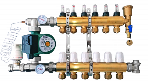
 A typical scheme of a combined heating system with the connection of radiators and underfloor heating circuits. This is the most technologically advanced and easily customizable option, but at the same time it requires significant initial investments. 1 - heating boiler; 2 - safety group, circulation pump, expansion tank; 3 - manifold for separate two-pipe connection of radiators according to the "star" scheme; 4 - heating radiators; 5 - underfloor heating manifold, includes: bypass, three-way valve, thermostatic head, circulation pump, combs for connecting underfloor heating circuits with gearboxes and flow meters; 6 - contours of the warm floor
There are a fairly large number of variations in the execution of the boiler room piping, while in each individual case, their own principles of operation of the hydraulic system apply. However, if you do not take into account extremely specific options, then there are only five ways to coordinate the operation of heating devices of various types:
- Parallel binding of the underfloor heating collector to the mains of the heating unit. The tie-in point in the line must be made up to the point of connection of the radiator network, the coolant supply is provided by an additional circulation pump.
- Association by type of primary and secondary rings. The main, wrapped in a ring, has several supply tie-ins in the supply part, the coolant flow in the connected circuits decreases as it moves away from the heating source. Flow balancing is performed by selection of the pump flow and flow limitation by regulators.
- Connection to the extreme point of the coplanar collector. The movement of the heat carrier in the underfloor heating loops is provided by a common pump located in the generator part, while the system is balanced according to the priority flow principle.
- Connection via a hydraulic separator is optimally suited for a large number of heating devices, a significant difference in flow rates in the circuits and a significant length of the underfloor heating loops. This option also uses a coplanar collector, while a hydraulic arrow is necessary to eliminate the pressure drop that interferes with the correct operation of the circulation pumps.
- Local parallel connection of the loop through the unibox. This option is well suited for connecting a short floor heating loop, for example, if necessary, heat the floor only in the bathroom.
 The simplest option is to turn on the underfloor heating circuit to a radiator heating system with a coolant temperature of 70-80 ° C. 1 - line with supply and return of the high-temperature circuit; 2 - contour of the warm floor; 3 - unibox.
It must be remembered that the nature of the work of a warm floor can also vary depending on the layout of the coil. The “snail” scheme is considered optimal, in which the pipes are laid in pairs, which means that the entire area is heated almost evenly. If the warm floor is arranged in a “snake” or “maze”, then the formation of colder and warmer zones is practically guaranteed. This disadvantage can be eliminated, including due to the correct settings.

Setting up a warm floor
And now, the heating system is filled and tested, the boiler is started. Everything is ready to set up the heating system.
Before starting the heating setup, it is necessary to determine its goals and objectives. The main task of balancing is not to set the required flow rate in each loop, but to establish the ratio of flow rates for loops or the balance of flow rates. It is worth remembering that the final flow rate is set during the setting of the pumping and mixing unit. By changing the total flow rate of the coolant through the collector, the ratio of flow rates through the loops will be preserved.
Setting up a warm floor using flow meters
The presence of flowmeters on the manifold block significantly affects the balancing. Flowmeters significantly speed up balancing and allow it to be done without turning on the boiler. This is possible because the flow meter shows the coolant flow for each circuit in real time.
The distribution of heat carrier flows must be carried out in such a way that the ratio of flow rates in the loops and the ratio of the required heat outputs coincide. To do this, it is desirable to know the required thermal loads on the hinges. But even if these data are not available, you can set the costs in proportion to the lengths of the loops. In most cases, this approach does not give a large error due to the fact that loops with large lengths also have large capacities.
Balancing starts with the longest loop, or the loop with the highest power, if known. Further, the control valve on this loop opens to the maximum position. In the future, the costs of all other loops will be displayed relative to it.
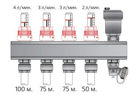
For example, consider a collector with four loops. Let's say that the lengths of the loops are as follows: 100, 75, 75 and 50 m.
As we have already said, the tuning begins with a larger loop, having a length of 100 m. It opens to the maximum. Assume that with the valve fully open, the flow on this loop is set at 4 l/min.
The coolant flow rate on the second and third loops should be: (75/100) 4 = 3 l/min.
The coolant flow rate on the fourth loop should be: (50/100) 4 = 2 l/min.
Problems when setting up a warm floor
In practice, it may turn out that on the third loop the flow rate with the valve fully open will be set at 2.5 l/min, although we need a flow rate of 3 l/min. This suggests that this loop has a greater hydraulic resistance than the second loop of the same length. As a rule, this happens due to the presence of a larger number of bends, rolls or supply sections. If this happens, then you will come, still turn on the boiler and carry out further balancing with the boiler turned on and at least with minimal heat removal in the room.
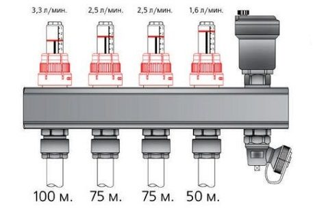
In this case, the first loop will be set to (100/75) 2.5 = 3.3 l / min, the second loop - to 2.5 l / min., and the fourth loop to - (50/75) 2.5 = 1.6 l/min.
After all costs in the loops are set, the balancing of the underfloor heating loops can be considered complete. The next step is to set up the pumping and mixing unit.
Setting up a warm floor without flow meters
If flow meters are not installed on the manifold, then the flow rates in the loops will have to be judged only by indirect signs.
Balancing without flow meters is carried out only with the boiler turned on and at least with minimal heat removal in the room. It is better if the temperature outside is not lower than +5 ºС, while the rooms should not have open windows and any significant heat emissions, for example, a working fireplace. The system should then be allowed to warm up for a few hours until the temperature in the loops stabilizes, after which it is necessary to evaluate the correctness of the adjustment made.
The correctness of the system setup is determined by one of the following methods:
- by the temperature of the heat carrier in the return pipeline;
- by average floor temperature.
Functionality and principle of operation of the flowmeter
The main function of flowmeters or, as they are also called, float rotameters in the underfloor heating system is to adjust the flow rate of the coolant in the water circuits. Installing such a device allows you to:
- to avoid excessive consumption of electrical energy in the process of heating the coolant;
- ensure uniform heating of all water circuits;
- eliminate temperature fluctuations in different rooms.
The need to use flow meters arises in buildings where floor coverings with different areas are heated. Large rooms require a longer pipeline, so they warm up less intensively than a small room. Therefore, it is possible to achieve uniform heating and ensure a comfortable temperature throughout the house only with such a device.
The floor heating flow meter is a mechanical type device with a plastic or brass body. Inside it is a polypropylene float. On the top of the case is a transparent flask with markings. In the process of circulation of the coolant, the float comes into action, moving up and down. According to its location, it is possible to determine the volume of liquid in the pipeline using a scale.
How to adjust a warm water floor manually preparation and input
Manual adjustment is carried out using a conventional tap, which is called a thermal head. It is mounted on the return and supply. Using a crane allows you not to load the system with automation and additional equipment. This significantly reduces costs, but creates a number of inconveniences. High-quality and quick adjustment of a warm water floor with a thermal head is a myth. The tap will have to be turned often, and when determining the temperature, rely solely on personal feelings.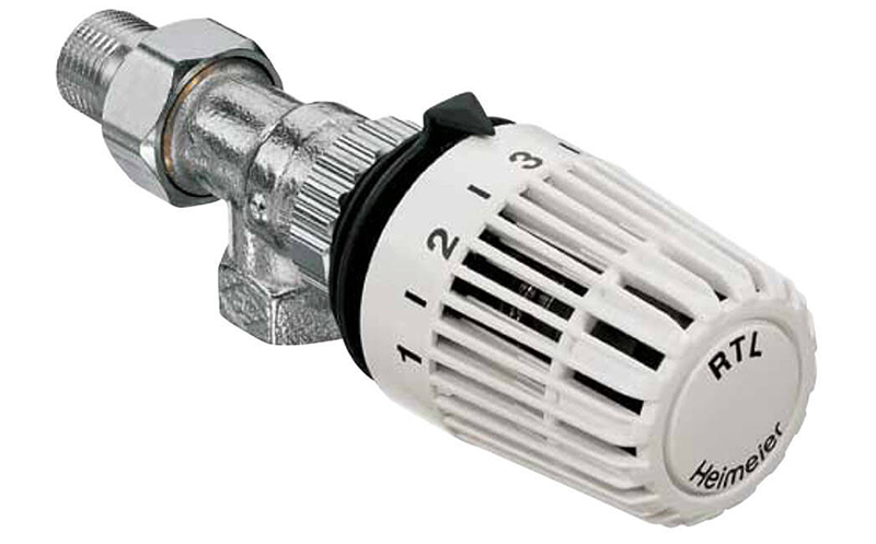
Important! It is considered more convenient to adjust water heated floors with rotameters (flow meters), which are installed at the inlet to each circuit (manifold installation site). All that is needed is to control the allowable difference in instrument readings
It is 0.3-0.5 liters.
Correct adjustment of a warm floor with a thermal head requires compliance with the commissioning standards for the entire system. Otherwise, the system of main or auxiliary heating of air masses from below the room will malfunction.
Temperature regime
Before proceeding with the adjustment of a warm floor, it is extremely important to establish a clear idea of \u200b\u200bthe purpose for which it is being performed. According to the principle of operation, a water-heated floor is fundamentally different from other heating devices.
The main difference is the operating temperature of the coolant. If the supply to the radiator network is carried out at temperatures up to 80 ° C, then the heating of the coolant entering the floor heating coil is limited to 40-42 ° C. This is necessary for reasons of comfort and safety. In normal mode, the temperature on the floor surface fluctuates in the range of 22-26 ° C, stronger heating causes discomfort.

There are two ways to control the heating temperature of a liquid underfloor heating. The first of them involves temperature control on the supply branch of the collector by mixing a portion of the cooled coolant from the return. Technically, this solution is implemented by installing a three-way valve with a thermostatic head RTL push-action. The difference between such a head and a radiator head is that it relies in operation on the temperature of the coolant, and not the air. With this method of regulation, the flow in the loops remains constant, only the temperature of the coolant changes with a small amplitude.
The second adjustment method involves limiting the flow of hot coolant in the circuit. In this case, a thermostatic head is also installed, but it is located on a two-way valve that interrupts the return flow circuit.With this method of regulation, the supply and return are connected by a bypass circuit, the flow through which is regulated by a restrictive valve with a pre-calibrated capacity. The principle of such regulation is based on the high inertia of the underfloor heating system. During operation, the coolant is supplied to the loops at the nominal temperature of the heating unit, only the total flow changes periodically. Thus, the heating of the screed occurs cyclically, that is, a significant heat capacity of the storage layer is required to smooth out temperature drops.

In both cases, one important rule applies: thermostatic fittings must necessarily rely on the return flow temperature of the loop or collector. The device can have a mechanical or electronic principle of operation, it can even be a conventional thermometer
The need for a correct location is due to the fact that it is almost impossible to judge the effectiveness of the adjustment by the value of the coolant temperature at the supply, because the length of the loops can differ significantly.
Balancing the underfloor heating loops
While preparing this article, I read many different opinions of specialists in setting up a warm floor. Here's what I disagree with:
You can often hear that it is possible to properly balance the underfloor heating system only with the help of calculations, by counting the resistance of all loops and calculating the adjustment position of the control valves. I do not argue that a competent hydraulic calculation will speed up the adjustment process and protect against installation errors. But in practice, setting up a warm floor can take place without theoretical calculations, although it will take more time. The most important thing is that a project with hydraulic calculation costs money, and we are aimed at competent savings.
Many experts believe that the flow rate of the coolant in all loops should be the same. In practice, the fluid flow in the loops mainly depends on the heat output that each particular loop transfers to the room.
There is an opinion that the underfloor heating system does not need to be balanced at all, and the coolant flow in the loops will even out by itself due to the operation of thermostats, controllers and other automation devices. I do not agree with this statement, since sooner or later conditions will come when all the underfloor heating loops will be forced to open to the maximum. In this case, the distribution of the coolant in the system must be such that all the liquid does not go into one loop, but is evenly distributed over all circuits.
Adjustment Features
For each separate room, a separate adjustment of the rotameters is carried out. Control is carried out according to the scheme of established circuits
This takes into account the level of heating of the liquid and pressure
It is recommended to perform balancing according to the following instructions:
- The total amount of coolant passing through the collector in one minute is determined. The figures are taken in liters. The resulting value is taken as 100 percent.
- The percentage flow of each individual water circuit is calculated. The result is converted to liters per minute.
- The flow meter controls the amount of liquid supplied to the pipeline.
By means of such actions it is possible to carry out a permanent correction of the water circuit. To indicate the actual parameters, it is necessary to observe the performance of the flow meter. According to the observations, it is possible to accurately determine the flow rate of the circuits connected to the collector.
Collector with flow meters for underfloor heating
Flow meter adjustment is performed depending on the installed model. After connecting the instrument to the manifold, a preliminary adjustment must be made by setting the initial position, which allows the liquid to enter.
In rotameters without a built-in valve, an additional locking device is used to set the "open" position. In this case, balancing is performed during the operation of the system.
Combined heat transfer meters can be pre-adjusted using full turns of the built-in valve. Each turn allows you to reduce the clearance by the set value.
Adjustment of the flow meter of the floor heating system is carried out taking into account the control of the liquid velocity in one minute - from 0.5 to 5 liters.
Before setting up the rotameter, you should check the status of the installed circuit. Trial testing is necessary to exclude the presence of leaks in the circuit, which can cause distortion of the indicators in the device.
The flow meter is an important element in a multi-circuit floor heating system. The device allows you to ensure a uniform flow of fluid in all individual pipelines. In order for the heating equipment to function as efficiently as possible, you should choose the right rotameter, as well as carry out its installation and configuration in accordance with the technical requirements.
Finally, the heating system of my house is assembled. Boiler started. Let me remind you that I decided to heat my house only with warm floors. Although there are not many rooms in the house, in order for the comfort in all rooms to be the same, it is necessary to set up a warm floor. That's how the underfloor heating is set up, we'll talk in this article.
Setting up a warm floor is not as difficult as it might seem at first glance. Generally speaking, setting up a warm floor consists of three stages. First, balancing the underfloor heating loops, then setting up the pumping and mixing unit, and finally setting up the controller if you decide to automate the heating system. I decided to fully automate the heating system in my house. Therefore, I purchased a controller, servos and thermal sensors. Let's take a closer look at the first stage of the setup, since the success of the entire setup depends on how well it is done.
Working with manifold meters
Hydraulic balancing of underfloor heating loops consists in rationing the flow in each coil. Depending on the length, a different amount of incoming coolant may be required so that when passing through the loop it cools exactly to the calculated value. The quantitatively required flow is defined as the ratio of the heat load on the loop to the product of the heat capacity of water or other coolant and the temperature difference in the supply and return: G \u003d Q / s * (t1 — t2).
Often you can find recommendations to determine the flow rate of the coolant according to the performance of the circulation pump, that is, to divide its supply in proportion to the ratio of the lengths of the loops. Such advice should be avoided: in addition to the fact that it is quite difficult to calculate the length of each coil, one of the most important rules is violated - to choose equipment parameters based on the needs of the system, and not vice versa. Attempts to distribute the flow in the described way almost always lead to the fact that the flow in the loops differs significantly from the calculated values, which makes further adjustment of the system impossible.
The very same adjustment of the flow with flow meters is quite simple. In some models, the throughput is changed by turning the body, in others - by rotating the stem with a special key. The scale on the body of the flow meter indicates the flow rate in liters per minute, you just need to set the appropriate position of the float. Almost always, when the throughput of one flow meter changes, the flow in the remaining loops changes, so the adjustment is carried out several times, successively calibrating each outlet.If such changes are especially pronounced, this indicates a lack of capacity of the control valve through which the collector is connected, or a too low performance of the circulation pump.