Instructions for installing heating from polypropylene pipes
Heating system installation
After the pipes for heating are selected, and the heating with polypropylene pipes with their own hands is carefully thought out and planned, the installation itself begins:
- Pipes should be installed with a slope towards the lowest section of the system. A drain cock or valve is installed in this place;
- In order to increase the ease of operation of the system and avoid various emergency situations, the pipeline is delimited into sections, each of which is easily blocked if necessary;
- When installing polypropylene pipes, secure fastening should be ensured. To do this, a special system of holders is mounted, which additionally prevent the formation of sagging in the pipeline;
- In the case when the riser needs to be divided into sections, it is possible to mount a fixed support for this purpose under and above the tee located at the branch point. This will help to avoid subsidence of the pipeline;
- Pipeline compensation is required between the fixed supports, which can be achieved in several ways:
- Changing the route of the pipeline;
- Installation of a compensator in the form of a loop;
- Installation of a U-shaped compensator.
- Do-it-yourself welding of polypropylene pipes is carried out in strict accordance with the instructions that are attached to the instruments and equipment used during installation, which control the welding parameters of polypropylene pipes;
- For cutting polypropylene pipes, only a sharply sharpened tool, such as a pipe cutter or special pipe cutting scissors, should be used;
- When self-installing a hot pipeline from polypropylene pipes, the transitions are made using a brass pressed-in insert with external and internal threads.
After the installation of the pipeline, it should be tested in order to identify and eliminate possible shortcomings and installation errors:
- When testing a pipeline, you can use a pipe deaeration device without installing water meters;
- Filling the pipeline should start from the lowest point in the system;
- When testing a pipeline, the length of the test section should not exceed 100 m;
- The pressure is increased gradually, bringing it to the maximum test level;
- The pipeline is tested for about an hour. This gap is usually enough to detect existing leaks.
After the installation is completed, the polypropylene pipes must together form a single heating system, installed in accordance with the developed project. To facilitate the work, you can familiarize yourself with the installation of a heating system from polypropylene reinforced pipes.
http://o-trubah.ru
TECHNICAL AND TECHNOLOGICAL CARD
The technical and technological map consists of sections.
1. Product name and scope. Here the exact name of the dish (product) is indicated, which cannot be changed without approval, the list of enterprises (branches), subordinate enterprises that have the right to manufacture and sell this dish (product) is specified.
2. List of raw materials used for the manufacture of the dish (product). All types of products necessary for the preparation of this dish (product) are listed.
3. Requirements for the quality of raw materials. A mark is put on the compliance of food raw materials, food products and semi-finished products used for the manufacture of this dish (product), with the requirements of regulatory documents, as well as on the availability of a certificate of conformity and a quality certificate.
4. Norms for laying raw materials in gross and net weight, output of semi-finished products and finished products. Here, the norms for laying products with gross and net weight for 1, 10 or more servings, the yield of semi-finished products and finished products are indicated.
5.Description of the technological process of preparation. This section should contain a detailed description of the technological process of preparing a dish (product), including cold and heat treatment modes that ensure the safety of the dish (product), as well as the use of food additives, dyes, etc. The technology for preparing dishes and culinary products should ensure compliance with the safety indicators and requirements established by the current regulations, in particular SanPiN 2.3.2.560-96.
6. Requirements for the design, serving, sale and storage, providing for the design features and rules for serving the dish (product), the requirements and procedure for the sale of culinary products, the conditions, terms of sale and storage, and, if necessary, the conditions of transportation. These requirements are formed in accordance with GOST R 50763-95, SanPiN 2.3.6.1079-01 and SanPiN 2.3.2.1324-03.
7. Indicators of quality and safety. These are the organoleptic indicators of the dish (product): taste, color, smell, consistency, the main physical, chemical and microbiological indicators that affect the safety of the dish (product), in accordance with GOST R 50763-95.
8. Indicators of nutritional composition and energy value. The section indicates data on the nutritional and energy value of the dish (product) (tables "Chemical composition of food products" approved by the USSR Ministry of Health), which are determined when catering for certain categories of consumers (organization of dietary, preventive, children's and other nutrition).
Each technical and technological map is assigned a serial number. The card is signed by a process engineer, responsible developer, approved by the head of the catering enterprise or his deputy. The period of validity of technical and technological maps is determined by the enterprise.
For terms, cost, clarification of information, please call 8 969 032 29 97, our specialists are always happy to answer all your questions.
Instructions for laying a heating plumbing from polypropylene pipes
Having made the choice of pipes for heating and having thoroughly prepared, proceed to direct installation:
- Pipe installation should be carried out with a slope, which should be made towards the lowest point in the system. A valve or drain cock should be located in this place.
- In order to avoid emergency situations, as well as for more convenient operation of the system, it is necessary to delimit the pipeline into sections that, if necessary, can be easily blocked.
- When installing polypropylene pipes, reliable fastening must be ensured by installing a system of special holders, which will also prevent the formation of sagging in the pipeline.
- If it is required to divide the system riser into several sections, then this can be achieved by installing a fixed support. The installation of such a support is carried out above and below the tee, which is located at the branch point, which will help prevent the pipeline from settling.
- Pipeline compensation required between fixed supports is achieved by the following methods: changing the route of the pipeline, installing a loop compensator, installing a U-shaped compensator.
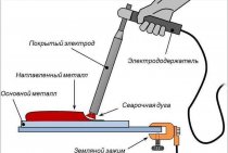
- Welding of heating pipes must be carried out strictly according to the instructions attached to the installation equipment and devices used to control the welding parameters.
- Cutting pipes made of polypropylene should be carried out only with sharply sharpened tools. As a cutting tool, special scissors or a pipe cutter are used.
- Self-installation of polypropylene pipes of a hot pipeline assumes the presence of transitions with a pressed brass insert, the thread of which must be external and internal.
- When the installation has already been completed, polypropylene pipes should be a pipeline installed in accordance with the project, clean, visible and accessible along the entire length for testing.
- During the test, it is not required to specially install water meters, it is enough to use only a pipe deaeration device.
- Pipe fittings should only be installed when they are able to withstand the pressure in the system. Mounted shutters must be open. However, it is preferable to replace such fittings with a cork.
- The pipeline is filled starting from the lowest point in the system.
- The length of the pipeline to be tested should not exceed 100 meters.
- The pressure is increased gradually until it reaches the test limit.
- The duration of the test is about an hour. This period of time is quite enough to detect leaks, if they occur (also find out how efficiently local sewage is carried out for a summer residence).
WHAT IS A TECHNOLOGICAL INSTRUCTION
A technological instruction (TI) is a special document that contains information about the sequence of technological processes for the production of products, and also regulates the rules for the implementation of this production, describes the methods of processing and disposal of goods.
The development of technological instructions is carried out, as a rule, in parallel with the technical specifications.
The TI used by the enterprise is a document that ensures the release of goods of good quality in accordance with all the requirements and standards established by the Legislation. Note that all the norms, characteristics and indicators, which are mandatory prescribed in the technological instructions, must be the result of experimental scientific work carried out by specialists in this field.
The development of TI is carried out in accordance with current international and state standards, as well as in accordance with the official rules for the preparation of technical documents and requirements for the content of TI.
The main sections of the developed TI include information about the product, which is the result of the production processes of the enterprise, information about the manufacturing procedure, information about the standards, requirements for the raw materials used, recipes, and so on. Certain sections of the TI are responsible for requirements regarding sanitary and hygienic and fire requirements for products, packaging and labeling rules, methods of storage and transportation of products.
Which pipes are suitable for the heating system
Heating systems are mounted from polypropylene pipes reinforced with fiberglass or aluminum foil. Such products are more durable and resistant to deformation, withstand pressure up to 25 atmospheres and temperatures up to 90 degrees.
Such pipes consist of several layers: the inner and outer layers are polypropylene, and a reinforcing layer is located between them. All of them are fastened with a special glue, due to which the pipe turns out to be actually five-layered.
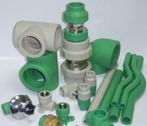
What fittings are needed for installation?
To connect the pipes to each other, to attach them to boilers and heating radiators (http://www.tdarsenal.ru/catalog/radiatory_otopleniya/), you will need a variety of fittings. These include:
- couplings for creating direct connections, involving fixation by soldering or threaded fastening;
- crosses, allowing to form the intersection and branching of pipes;
- corner joints that ensure the rotation of the pipe;
- Ball Valves;
- fixing supports on which pipes are installed;
- compensators;
- contours;
- fittings for fastening faucets and other plumbing fixtures.
The above list cannot be called exhaustive: in each case, the type and number of fittings is determined individually, depending on the installation features.
How is the heating system installed?
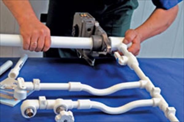
For installation, you will need two tools - for cutting pipes and soldering them. The first device is necessary for preparing fragments of a given length: it can be a manual, electric or battery device that provides an accurate and clean cut.You should not cut pipes with a grinder or a circular saw: theoretically, such devices can easily cope with polypropylene, but they will not provide proper cut cleanliness, and the pipe will not be airtight.
The apparatus for soldering (or welding) polypropylene pipes allows you to form a strong, reliable and tight connection. Welding is very simple: the pipes are put on nozzles on both sides of the apparatus, the polypropylene is heated and softened, after which both fragments should be pressed against each other and held for about 30 seconds until the joint hardens.
Thus, pipes of any diameter and purpose can be connected. However, before starting work, it is better to sketch the proposed pipeline diagram and subsequently mount the system in accordance with it so that there are no errors and shortcomings.
The finished sections of the system are mounted using fittings, connected to the boiler and radiators. If the installation was carried out correctly, the system is ready for operation immediately after it.
REQUIREMENTS FOR THE DESIGNATION OF TECHNOLOGICAL INSTRUCTIONS
The designation of the technological instruction for the manufacture of products, the requirements for which are established by the standard, includes the abbreviation "TI", through a space, the designation of the standard (for service stations without a year of approval) and then through a dash, a three-digit registration number assigned by the enterprise (organization) - the holder of the original.
Examples:
1. TI GOST R 50763-2018-XXX
2. TI STO 00437205-003-XXX
The designation TI for the manufacture of products, the requirements for which are established by the technical conditions of the TU, includes the abbreviation "TI", through the space, the designation TU without the year of approval.
Example: TI TU 1234-003-00437205
Requirements for the installation of heating with propylene plumbing
Fittings for mounting a pipeline made of polypropylene
Consider the basic requirements for the installation of a pipeline made of polypropylene pipes:
- When installing a polypropylene water supply system, elements without contamination and damage should be used, therefore, during their transportation and storage, all norms and requirements should be observed;
- Installation of pipes made of polypropylene should be carried out at an air temperature of at least 5 °, which allows you to connect pipes efficiently and reliably;
- PP pipes for heating during storage and transportation should be protected not only from mechanical influences, but also from the action of open fire;
- Crossings of polypropylene pipes, if necessary, should be performed using a special connecting piece - crossing;
- For threaded connections, threaded fittings should be used rather than threading yourself;
- The tightness and reliability of the connections is ensured by Teflon or FUM tape or other similar sealant.
Types of installation of heating pipes
The most popular autonomous heating schemes, perhaps, can be called systems with a lower and upper spill. The installation of systems of this type is due to the installation of steel or polypropylene pipes. By the way, during installation, you can use welding.
In a heating system with a top spill, the installation of a circulation pump is not required, since the main principle of such systems is the circulation of water by gravity. This method is effective in cases where the building experiences frequent power outages.
Installation of a system with a bottom spill (radial piping) has the following advantages:
- relatively high efficiency of the heating system;
- the possibility of installing pipes of smaller diameter by providing a certain pressure with a pump;
- this type of pipeline can be completely hidden in the floor and walls.
In this case, the contour is created by installing a pipeline made of plastic or metal-plastic, as when replacing pipes in an apartment, which allows you to make the required connections and bends. This is the most common installation option and the choice of pipe for underfloor heating.
In rare cases, more expensive copper pipes can also be used as circuits, which, in comparison with plastic pipes, have a higher heat transfer.
n1.doc
TYPICAL TECHNOLOGICAL CHART (TTK) INSTALLATION OF RISERS AND HEATING DEVICES OF A SINGLE-PIPE SYSTEM OF CENTRAL HEATING DURING MAJOR REPAIRS OF RESIDENTIAL HOUSESI. Scope of the map II. Organization and technology of the construction process 21. Basic requirements for the quality of work: Safety rules:III. Technical and economic indicators
| Labor intensity for one riser of a four-story house (with two radiators in each floor) | 2.76 man-days |
| Output per worker per shift | 0.42 riser |
IV. Material and technical resources
| N p / p | Name | unit of measurement | Quantity | |
| Main design, semi-finished products and materials | ||||
| 1. | Risers made of steel pipes | PC. | 1 | |
| 2. | Steel pipes for radiators | PC. | 20 | |
| 3. | Radiators | PC. | 10 | |
| 4. | Brackets for radiators | PC. | 30 | |
| 5. | Clamps, metal sleeves for passing the riser through the floors | PC. | 5+5 | |
| 6. | Drives | PC. | 20 | |
| 7 | Valves of one adjustment + couplings | PC. | 10+10 | |
| 8. | Lock nuts + radiator liners | PC. | 20+20 | |
| 9. | Radiator plugs | PC. | 20 | |
| 10. | Linen | PC. | 35 | |
| 11. | Minium (whitewash) | PC. | 150 | |
| 12. | Welding wire | PC. | 750 | |
| Machinery, equipment, tools, inventory and fixtures | ||||
| 1. | Construction and mounting gun SMP-1 | PC. | 1 | |
| 2. | Gas welding machine with a set of tools | PC. | 1 | |
| 3. | Pipe wrenches No. 2 | PC. | 1 | |
| 4. | hacksaw | PC. | 1 | |
| 5. | Hacksaw blades | PC. | 2 | |
| 6. | plumb line | PC. | 1 | |
| 6. | Trowel (trowel) | PC. | 2 | |
| 7. | Locksmith's hammer 500-800 g | PC. | 2 | |
| 8. | Bench chisel | PC. | 1 | |
| 9. | Sliding wrenches | PC. | 1 | |
| 10. | folding meter | PC. | 2 | |
| 11. | pliers | PC. | 1 | |
| 12. | Jumper | PC. | 2 | |
| 13. | Electric drill | PC. | 1 | |
| 14. | Syringe Grigoriev | PC. | 1 | |
| 15. | Portable ladder | PC. | 1 | |
| 16. | carpentry level | PC. | 1 | |
| 17. | Klupp pipe with a set of dies | PC. | 1 | |
| 18. | Pipe clamp | PC. | 1 |
V. Schedule, work performance
| N p / p | Name of works | Unit of measurement | Scope of work | Labor intensity, per unit of measure people - h | Labor capacity for the entire scope of work, people - day | Profession, rank and quantity, used mechanisms | Hourly work schedule | ||||||
| 1 | 2 | 3 | 4 | 5 | 6 | 7 | |||||||
| 1. | Installation of radiators with marking places, drilling holes and installing brackets | 1 device | 10 | 0,71 | 0,90 | Locksmith4 res. - 13 digits - 1 Gas welder: 5 digits - one | — | 3— | |||||
| 2. | Installation of a riser pipeline and connections to radiators with marking and drilling holes in ceilings, partitions, gas welding | 1m pipe-wire | 34,0 | 0,34 | 1,46 | Gas welding machineConstruction and assembly gun SMP-1 | — | 3— | — | — | — | ||
| Total | 2,36 |
VI. Labor costing Table 3
| N p / p | Grounds for the adopted norms for ENiR | Scope of work | Unit of measurement | Scope of work | Norm time unit of measurement, people - h | Priced per unit of measurement, rub. - kop. | Labor costs for the entire scope of work, people - h | The cost of labor costs for the entire scope of work, rub. - kop |
| 1. | 9-1-1, paragraph 1. 2, 3 | Marking places for laying and drawing measurement sketches of pipelines | 100 m | 34,0 | 3,75 | 2-97 | 0,16 | 1-00 |
| 2. | 9-1-31, vol. 2, item 2 | Drilling holes in floors | 100 holes | 4 | 7,1 | 3-94 | 0,04 | 0-16 |
| 3. | 9-1-2, vol. 2, item 2, | Laying of steel pipelines | 1m | 34,0 | 0,25 | 0-14,8 | 1,06 | 4-85 |
| 4. | 22-17, p. 9 | Gas welding of pipelines (fixed vertical joint) | 10 joints | 5 | 0,95 | 0-66,7 | 0,05 | 0-35 |
| 5. | 9-1-12, vol. 3 | Installation of radiators with drilling holes in the walls | 1 device | 10 | 0,71 | 0-40,3 | 0,90 | 4-03 |
| 6. | 22-17, p. 14 | Gas welding of pipelines (fixed horizontal joint) | 10 m | 10 | 1,1 | 0-77,2 | 0,15 | 0-75 |
| Total | 2,36 | 11-14 |
REQUIREMENTS FOR QUALITY AND ACCEPTANCE OF WORKS
3.1. Prior to the commencement of works on the installation of BAMTP, the construction readiness of the premises of the heating point and the incoming quality control of the materials used, blanks, measuring instruments, their compliance with standards and technical specifications are accepted.
3.2. Upon acceptance of the BAMTP at the facility, their dimensions, the presence of damage during transportation, and the completeness of the blocks are checked. It is necessary to comply with the acceptance rules specified in the "Rules for accounting for the supply of thermal energy" (Soyuzenergo, 1986).
3.3. Technical criteria and controls for operations and processes are given in Table 6.
3.4. Acceptance control of mounted units is carried out in accordance with SNiP 3.05.01-85.
Labor costs and wages for installation and welding work for BAMTP from functional units, man-hour / rub.
|
Block diameter, mm |
||||||
|
40 |
50 |
80 |
100 |
125 |
150 |
|
|
1 |
10,63 8,960 |
11,24 9,474 |
11,57 10,554 |
21,50 18,136 |
22,27 18,584 |
23,08 19,648 |
|
2 |
11,18 9,425 |
11,36 9,569 |
12,77 10,712 |
21,60 18,215 |
23,20 19,431 |
23,95 20,319 |
|
3 |
11,23 9,465 |
11,41 9,609 |
12,84 10,689 |
21,80 18,373 |
22,46 18,821 |
23,38 19,117 |
|
4 |
11,66 9,806 |
11,98 10,062 |
13,47 11,268 |
22,68 19,070 |
23,36 19,614 |
24,29 20,636 |
|
5 |
11,78 9,901 |
12,10 10,157 |
13,67 11,426 |
23,52 19,769 |
24,36 20,429 |
25,36 21,515 |
|
6 |
11,83 9,941 |
12,41 10,403 |
13,64 11,403 |
22,98 19,307 |
23,62 19,819 |
24,55 20,841 |
|
7 |
11,65 9,798 |
11,90 10,092 |
13,46 11,260 |
22,600 19,007 |
24,10 20,224 |
24,98 21,214 |
|
8 |
11,77 9,893 |
12,02 10,093 |
13,66 11,418 |
23,44 19,696 |
24,36 20,429 |
25,36 21,515 |
|
9 |
11,82 9,933 |
12,07 10,133 |
13,63 11,395 |
23,64 19,844 |
24,36 20,429 |
25,28 21,451 |
Labor costs and wages for installation work for BAMTP from separate functional units, man-hours / rub.
|
Block diameter, mm |
||||||
|
40 |
50 |
80 |
100 |
125 |
150 |
|
|
1 |
8,69 7,42 |
9,12 7,79 |
9,85 8,40 |
17,80 15,21 |
17,80 15,21 |
18,54 15,82 |
|
2 |
9,12 7,79 |
9,12 7,79 |
9,85 8,40 |
17,80 15,21 |
18,54 15,82 |
18,97 16,19 |
|
3 |
9,12 7,79 |
9,12 7,79 |
9,85 8,40 |
17,80 15,21 |
17,80 15,21 |
18,54 15,82 |
|
4 |
9,12 7,79 |
9,12 7,79 |
9,85 8,40 |
17,80 15,21 |
17,80 15,21 |
18,91 16,19 |
|
5 |
9,12 7,79 |
9,12 7,79 |
9,85 8,40 |
18,54 15,82 |
18,54 15,82 |
19,70 16,80 |
|
6 |
9,12 7,79 |
9,12 7,79 |
9,85 8,40 |
17,80 15,21 |
17,80 15,21 |
18,91 16,19 |
|
7 |
9,12 7,79 |
9,12 7,79 |
9,85 8,40 |
17,80 15,21 |
18,54 15,82 |
19,70 16,80 |
|
8 |
9,12 7,79 |
9,12 7,79 |
9,85 8,40 |
18,54 15,82 |
18,54 15,82 |
19,70 16,80 |
|
9 |
9,12 7,79 |
9,12 7,79 |
9,85 8,40 |
18,54 15,82 |
18,54 15,82 |
19,70 16,80 |
Labor costs and wages for installation work for BAMTP from enlarged blocks man-hour / rub.
|
Block diameter, mm |
||||||
|
40 |
50 |
80 |
100 |
125 |
150 |
|
|
1 |
5,70 4,94 |
6,00 5,20 |
6,50 5,62 |
7,55 6,50 |
13,75 11,89 |
14,85 12,81 |
|
2 |
6,00 5,20 |
6,00 5,20 |
6,50 5,62 |
7,55 6,50 |
13,75 11,89 |
14,85 12,81 |
|
3 |
6,00 5,20 |
6,00 5,20 |
6,50 5,62 |
7,55 6,50 |
13,75 11,89 |
14,85 12,81 |
|
4 |
6,00 5,20 |
6,00 5,20 |
6,50 5,62 |
7,55 6,50 |
13,75 11,89 |
14,85 12,81 |
|
5 |
6,00 5,20 |
6,00 5,20 |
6,50 5,62 |
7,55 6,50 |
13,75 11,89 |
14,85 12,81 |
|
6 |
6,00 5,20 |
6,00 5,20 |
6,50 5,62 |
7,55 6,50 |
13,75 11,89 |
14,85 12,81 |
|
7 |
6,00 5,20 |
6,00 5,20 |
6,50 5,62 |
7,55 6,50 |
13,75 11,89 |
14,85 12,81 |
|
8 |
6,00 5,20 |
6,00 5,20 |
6,50 5,62 |
7,55 6,50 |
13,75 11,89 |
14,85 12,81 |
|
9 |
6,00 5,20 |
6,00 5,20 |
6,50 5,62 |
7,55 6,50 |
13,75 11,89 |
14,85 12,81 |
|
Instrument name |
Scheme 1 - 3 |
Scheme 4 - 9 |
||
|
Diameter 40 - 100 mm |
Diameter 125; 150 mm |
Diameter 40 - 100 mm |
Diameter 125; 150 mm |
|
|
pressure gauge |
4 |
6 |
4 |
6 |
|
Thermometer |
4 |
4 |
4 |
4 |
|
Regulator |
2 |
2 |
3 |
3 |
|
water meter |
1 |
2 |
1 |
2 |
3.5. Upon acceptance of works, logs of installation and welding works, certificates of examination of hidden works are presented.
Technical criteria and controls
|
Subject of control |
Tool and method of control |
Control time |
Responsible Controller |
Technical criteria for quality assessment |
|
|
Preparatory pre-assembly work |
Compliance of the geometric dimensions of the blocks with the design ones, the presence of external defects |
Metal tape measure |
Before installation |
Master |
Size deviation according to TU 36-808-85 |
|
Setting item or individual blocks |
Horizontalness of the base, verticality of the block, distance from the walls |
Level, plumb line, tape measure, meter |
During installation |
Brigadier (link) |
No deviation |
|
Connection of the heat point (blocks to each other) to the pipeline of the heating network and the heating system by welding |
Weld quality |
Visually and in leak test |
Too |
Too |
According to GOST 3242-79 |
|
Installation of a water meter, flow regulator |
Strength and tightness of flange connections |
Too |
² |
² |
Too |
|
Installation of manometers and thermometers |
Strength and tightness of threaded connections |
² |
² |
² |
² |
|
Notes: 1. The pressure gauges used in the tests must be verified (have a stamp with the valid verification period). 2. The substation is tested together with the heating system upon delivery. 3. During the working check of the systems served by the point, it is turned off. |
1 area of use
Building
residential, consists of 10 floors, floor height
3.0 m, floor thickness 0.2 m. Walls
brick, there are radiator niches.
Radiators are located under the windows.
The premises are living quarters. In a buiding
single pipe system adopted
heating with top wiring. Eyeliners
to radiators are made of pipes
diameter 15 mm, riser diameter - 25 mm,
highways -40mm. Pipes are accepted
for installation steel water and gas pipelines
according to GOST 3262-75. Mounting
joints are made with welded
cups.
V
as heating appliances
cast-iron radiators MS-140 are accepted.
The scope of installation work is determined
calculation and is given in the table
form.
Mounting volume
works.
Table 4
|
Name |
Unit |
Scope of work |
Rationale |
|
markup |
100 m |
3,80 |
380 |
|
acquisition |
1 t |
4,86 |
4,86 |
|
fastening |
1 approx. |
90 |
90 |
|
pad |
1m |
284 |
284 |
|
too |
1m |
96 |
96 |
|
first working |
100m |
3,80 |
380 |
|
checking for |
1 app. |
90 |
90 |
|
working check |
100 m |
3,80 |
380 |
|
final |
100 m |
3,80 |
380 |
|
final |
100 |
7,13 |
E § 9-1-8 |
|
examination |
1 PC. |
140 |
E § 9-1-8 |
Calculation
labor costs.
Table 5
|
№ |
base |
Name |
Compound |
Unit and gp |
Volume T |
per unit rev. |
On the man-hour |
|
|
Norm |
Rust |
|||||||
|
1 |
E |
markup |
el.-san. |
100 |
3,8 |
1,2 |
12,7 |
4,56 |
|
2 |
E§ 9-1-41 |
picking |
el.-san 3r-2 |
1 t |
4,86 |
3 |
250 |
14,6 |
|
3 |
E |
installation of radiators |
el.-san 3r-1 |
1 |
90 |
0,24 |
32,0 |
24 |
|
4 |
Е§ |
pad |
el.-san 3r-2 |
1 m |
284 |
0,21 |
15,6 |
59,64 |
|
5 |
E § 9-1-2 |
pad |
el.-san 3r-2 |
1m |
96 |
0,23 |
17,1 |
22,1 |
|
6 |
E |
first |
el.-san 4r-1 3r-1 |
100 |
3,8 |
5,3 |
42,4 |
20,14 |
|
7 |
Е§ |
warm-up check |
el.-san 5r-1 |
1 |
90 |
0,11 |
1,17 |
11 |
|
8 |
E § 9-1-8 |
working check |
el.-san 5r-1 4r-1 |
100 |
5.8 |
2,8 |
25,8 |
10,64 |
|
9 |
E § 9-1-8 |
final |
el.-san 5r-1 |
100 m |
3,8 |
2,3 |
22,7 |
8,74 |
Installation
carried out in a streaming manner. Based
labor costing
work schedule is drawn up
(table 6). Work schedule
includes a list of works, volumes
work, labor intensity, composition of the link and
breakdown of work by days.
Numerical
qualification composition of units
determined on the basis of analysis
work schedule and descriptions
composition of work operations in the UNiR
Sat. 9 issue 1 1987
ROUTING
The technological map (TC) should answer the questions:
1. What operations need to be performed
2. In what sequence are the operations performed
3. With what frequency it is necessary to perform operations (when the operation is repeated more than once)
4. How long does it take to complete each operation
5. The result of each operation
6. What tools and materials are needed to perform the operation.
Technological maps are developed in case of:
1. High complexity of the operations performed;
2. The presence of controversial elements in operations, ambiguities;
3. If necessary, determine the labor costs for the operation of the facility.