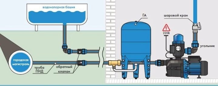
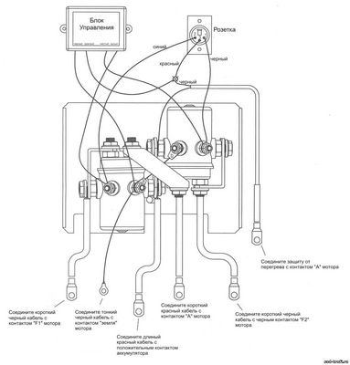
Wiring diagram
Depending on the type of pump, the connection diagram may vary.
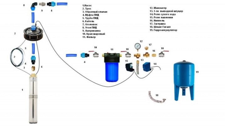
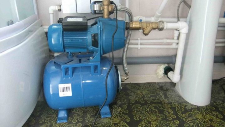
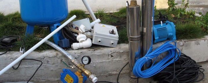
Installation and connection of a submersible pump and automation
For each generation of automation, the connection scheme to the pumping system has its own differences, often its features are described in the operating instructions.
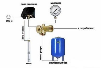
Consider the connection diagram using the example of equipping a submersible pump with 1st generation automation with a hydraulic accumulator.
- First, the accumulator is tied. Nodes are connected in series according to the scheme. Fum tape is used to seal threaded connections.
- The first “American” sits on the thread, with its help, during operation, the accumulator will be serviced in order to replace the membrane.
- On the other side, a bronze adapter with threaded branches is screwed to the "American".
- Two knots are screwed to them: a pressure gauge and a pressure switch.
- Next, a PVC pipe is installed by means of a fitting adapter on the end face of the bronze adapter of the hydraulic accumulator.
- On the other hand, the pipe is attached with a fitting to the pump.
- The supply pipe and the pump are laid on a flat area.
- A safety cable with a spare length of 3 meters is attached to the loops of its body.
- A cable and a cable are attached to the pipe with an interval of 1.5 meters with clamps. The second end of the safety rope is fixed next to the casing.
- After that, the pump is lowered into the well, and the safety cable is pulled.
- Next, the casing pipe is covered with a protective cap that protects the well from clogging.
- The cable is connected to the relay and led to the control cabinet.
- Immediately after connection, pumping of water into the accumulator begins. At this point, it is necessary to bleed the air by opening the valve.
- After water flows without air, the tap closes and the pressure gauge is checked. As a standard, the relay has settings for the upper pressure limit - 2.8 atm, and for the lower one - 1.5.
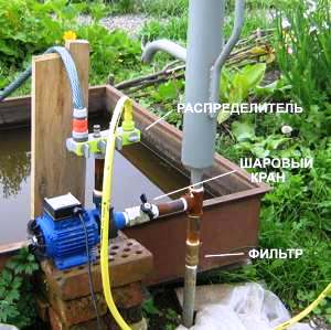
Installation and connection of a surface pump with automation
With this type of pump, the connection of automation has a number of differences, although the sequence of its connection is the same as for the submersible type. The differences are as follows:
- a PVC pipe is connected to the pump inlet for water intake from diameters from 25 to 35 mm;
- a check valve is attached to the second end by means of a fitting and lowered into the well, while the pipe must have a length sufficient for its end to be immersed in water by about a meter, otherwise air will be trapped;
- before starting work, the engine is filled with water through the filler hole and the intake pipe;
- with the correct hermetic connection of all nodes, turning on the pump will be accompanied by pumping water.
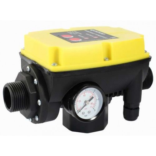
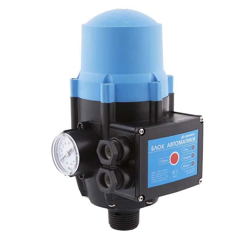
Well automation unit
These are already more advanced systems, which cost 10-15 times more than a conventional pressure switch. For this money, you will get convenient control of the minimum and maximum pressure on the LCD display, built-in protection against dry running, protection against pump jamming, and in some models, automatic starts after a certain period of time after the pump stops due to an error.
It would also be useful to supplement these automatic regulators for a well with a hydraulic accumulator. As a rule, they put small tanks on such systems, with a volume of about 5 liters, in order to compensate for water hammer.

Kinds
All automation used to control the operation of the pump is divided into 3 types in chronological order according to the sequence of its creation.
1st generation
This is the first and simplest automated control system for pumping equipment. It is used for simple tasks when it is necessary to provide a constant source of water in the house. It consists of three main parts.
-
Dry run sensor.
It is necessary to turn off the pump in the absence of water, which serves as a cooler, without it the pump will overheat and the winding will burn out. But an additional float switch can also be installed. Its function is similar to a sensor and is repelled by the water level: when it drops, the pump turns off. These simple mechanisms reliably protect expensive equipment from damage. -
Hydraulic accumulator.
It is a necessary element for system automation. Performs the function of a water accumulator, inside of which the membrane is located. -
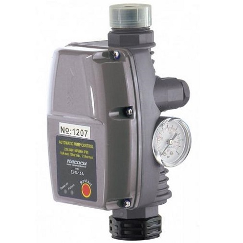
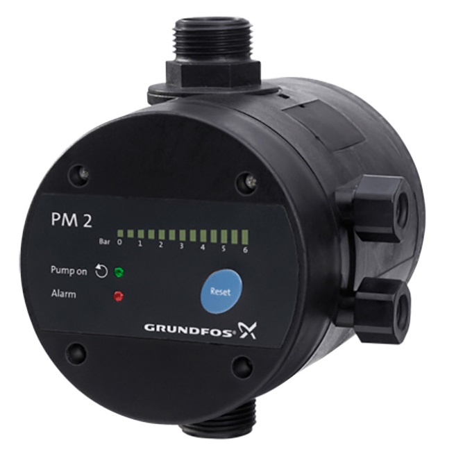
Relay
. The device that controls the pressure level must be equipped with a pressure gauge that allows you to set the operating parameters of the relay contacts.
Dry running sensor
Hydraulic accumulator
Pressure switch
Automation of the first generation for deep well pumps is simple due to the absence of complex electrical circuits, and therefore its installation on any pumping equipment is not a problem.
The functionality of the system is as simple as the mechanism of operation, which is based on a decrease in pressure in the accumulator when water is used up. As a result, the pump turns on and fills the tank with new fluid. When full, the pump turns off. This process continues cyclically
. Adjustment of the minimum and maximum pressure by means of the relay is possible. The pressure gauge allows you to set the lower and upper limits for the operation of automation.
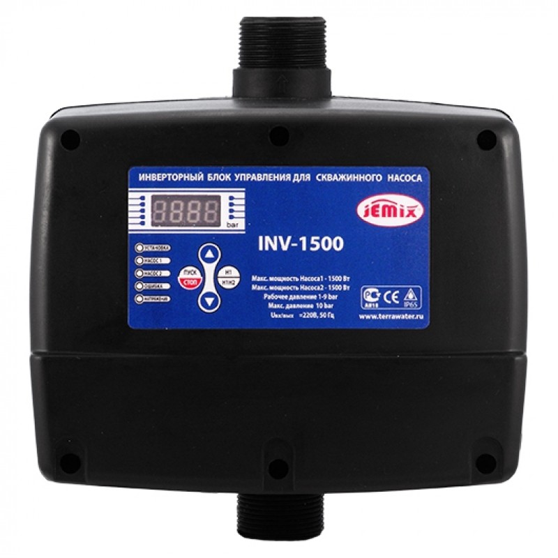
2nd generation
The second generation differs from the first in the use of an electronic control unit to which the sensors are connected. They are distributed throughout the pumping system and monitor the operation of the pump itself and the condition of the pipeline. All information is sent to the electronic unit, which processes it and makes appropriate decisions.
When using 2nd generation automation, a hydraulic accumulator may not be used, since the pipeline and the sensor installed in it perform a similar function. When the pressure in the pipe drops, the signal from the sensor goes to the control unit, which, in turn, turns on the pump and restores the water pressure to the previous level, and when completed, turns it off.
To install automation of the 2nd generation, basic skills in handling electronics are required.
According to the principle of operation, the systems of the 1st and 2nd generation are similar - pressure control, but the cost of the 2nd generation system is much more expensive, as a result of which it is in less demand.
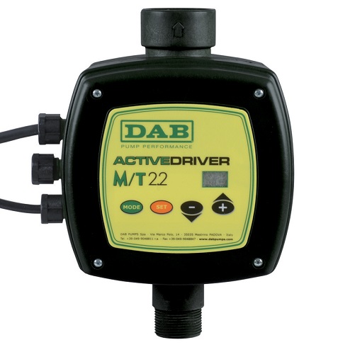
3rd generation
Such a system is highly reliable and efficient, but also more expensive than its predecessors. The precise operation of the system is ensured by advanced electronics and saves on electricity. To connect this system, a specialist is needed who will not only install, but also configure the correct operation of the unit. Automation provides a full range of equipment protection against breakdown, from dry running and pipeline rupture to protection against power surges in the network. The principle of operation, as in the 2nd generation, is not associated with the use of a hydraulic accumulator.
The main difference is the ability to more accurately regulate the operation of mechanical components.
For example, when turned on, the pump normally pumps water at maximum power, which is not necessary with its low consumption, and electricity is consumed to the maximum.
1 Types and differences of submersible pumps
Before understanding automation, we must understand what types of pumps exist. There are only two types of submersible pumps worldwide:
- Vibrating.
We all know that the above types of automatic submersible pumps are installed only in the water that these pumps pump.
That is why it is called "submersible". Most summer residents and lovers of country houses believe that it is much better than surface ones, but one can argue with that.

In principle, the operation of these pumps is the same for them, but the mechanism itself is different from each other. It should also be noted that their working conditions are also different. On wells of any depth, submersible pumps can be used, they need to increase the water pressure in order to pump the input up. It should be noted that submersible pumps operate at a depth in the well up to 10 meters.
If you have a well over ten meters, then highly specialized pumping systems are used to pump water from the depths.
For greater depths, it is best to use vibration pumps, which are most often used in water wells. But the centrifugal pump is most often used in the agricultural sector, where water supply is used.
The main element in the vibrating device is the membrane. When the mechanism vibrates, the membrane deforms. As a result, there is a pressure difference in the system. As a result, we get the effect of pumping liquid in the direction you need.
The following types of pumps work according to this principle:
- Aquarius.
- Gardena.
Before buying the above pumps, make sure they have a thermal switch. Also, when buying, you need to check the operation of the water intake at the bottom of the pump. If you have heavy soil in your summer cottage or country house, then it is advisable to install a vibration device as low as possible.
This is done so that the well (well walls) does not collapse, and also that the vibrating device installed in the ground is not contaminated by various objects. It is also desirable to install vibration models only in fortified springs. But pumps of the brand Aquarius, Gardena or Malysh are easy to assemble and dismantle.
You can make repairs quickly with your own hands. If we decide to consider the working mechanism of a centrifugal pump, then you can immediately see that special wheels are attached to it to the shaft, which is only one. Here you can see that the difference in pressure is produced by the rotation of the blades on the wheels. As a result of this, the liquid is pumped in the direction you need. The most popular models in the CIS are centrifugal pumps.
There are several reasons for this. The models are stable and have acquired considerable versatility in use. Also, such pumps - models can be connected with your own hands and will not be spent on this. And this saves the cost of arranging water supply.
Do-it-yourself automation for a well or with the help of professionals
General principle of operation of automation
Despite the difference in price and functionality, modern automatic units work according to the same scheme - various sensors monitor the pressure level and adjust it as necessary.
A good example is the principle of operation of the simplest pressure switch:
- The device is installed in two positions - the maximum and minimum pressure in the system - and is connected to the accumulator.
- The accumulator membrane reacts to the amount of water, that is, to the pressure level.
- When the minimum allowable level is reached, the relay turns on, which starts the pump.
- The pump stops when the top sensor is triggered.
More advanced systems that operate without a hydraulic accumulator can be equipped with additional options, but the main principle of operation of automation for a borehole pump remains unchanged.
Types of automation for borehole pumps
First generation ↑
The first (simplest) generation of automation includes the following devices:
- Pressure switch;
- Hydraulic accumulator;
- Dry run sensors-blockers;
- Float switches.
The pressure switch was mentioned above. Float switches react to a critical drop in the liquid level by turning off the pump. Dry running sensors prevent the pump from overheating - if there is no water in the chamber, the system stops functioning.As a rule, such a scheme is used in surface models.
The simplest automation for a borehole pump can be easily installed with your own hands. The system is also suitable for drainage equipment.
Second generation ↑
Block machines of the second generation are more serious mechanisms. It uses an electronic control unit and several sensitive sensors fixed in different places of the pipeline and pumping station. The signals from the sensors are sent to the microcircuit, which maintains full control over the operation of the water supply system.
The electronic "watchman" reacts in real time to any deviations from the norm. In addition, it can be equipped with additional features:
- Temperature control;
- Emergency shutdown of the system;
- Checking the liquid level;
- Dry run blocker.
Important! The big disadvantage of such an automation scheme for borehole pumps is the need for fine-tuning, a tendency to breakdowns and a rather high price.
Third generation ↑
Important! If you do not have experience in water supply, you will not be able to install automation for a well with your own hands. Only a specialist can determine which algorithm is better to program the system
Do-it-yourself automatic block ↑
Do-it-yourself automation for a borehole pump is often cheaper than a factory set of equipment. When buying units separately, you can always choose the best option for the purchased pump model without overpaying for unnecessary additional options.
Important! Such amateur performance requires a certain level of knowledge. If you cannot call yourself an expert, it is better to purchase pumping equipment with pre-installed automation.
Basic assembly schemes ↑
Among the automation schemes for borehole pumps, the following types have proven themselves well:
All automation nodes are assembled in one place. In this case, the accumulator can be located on the surface, and water is supplied to it through a pipe or flexible connection. The scheme is suitable for both surface and deep-well pumps.
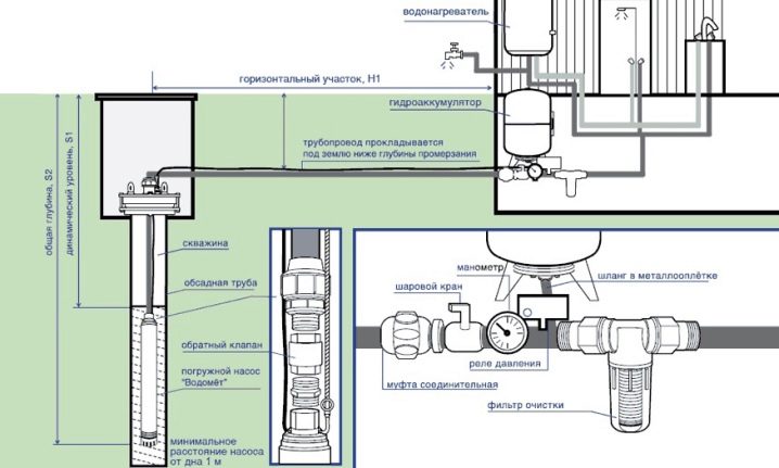
Control unit on hydraulic accumulator
With this arrangement, it is recommended to connect the system manifold to the pump supply pipe. It turns out a distributed station - the unit is located in the well, and the control unit with a hydraulic accumulator is installed in the house or utility room.
Distributed pumping station
The automation unit is located near the cold water collector, maintaining a constant pressure level in it. The pressure pipe departs from the pump itself. With such a scheme, it is better to use surface models.
Installation Tips ↑
In order for automatic equipment to serve you faithfully, you need to take care of the correct place for its installation in advance:
- The room must be heated all year round.
- The closer to the well is the remote unit, the better. The ideal option is to equip a small boiler room near the caisson.
- To avoid pressure losses, install the pumping station in close proximity to the collector.
- If the equipment will be located in the house, carry out high-quality soundproofing of the room.
Well Mechanical Pressure Regulator
The easiest and cheapest way to automate a well is to put a mechanical pressure regulator on it. It works quite simply, water creates pressure in the capsule, and if it is not enough, then the contacts close and the pump turns on, as soon as the tap closes, the pressure increases and the contacts open.


It happens that such pressure switches are equipped with a pressure gauge, but the most inexpensive models are deprived of this. Such a relay can be installed at any point of the pipeline, the pressure in the pipe is the same everywhere.The most significant drawback of this device is the lack of protection against “dry running” and if, for some reason, the water in the well runs out and the pressure in the system drops, the pressure switch will supply electricity to the pump, and the pump will work until it comes out of building.
The second point is the presence of a hydraulic accumulator in the system. It performs at least two functions:
- Prevents frequent switching on of the pump.
- It takes over the water hammer that occurs when the tap is suddenly closed.
How a hydraulic accumulator works
A hydraulic accumulator is a tank made of ferrous metal or stainless steel. As a rule, they are painted blue and have a capacity of 5 to 500 liters. The number of pump starts depends on the volume of the tank. With a small water consumption in systems equipped with small volume hydraulic accumulators (up to 50 liters), frequent pressure drops in the water pressure can easily be observed. Hydraulic accumulator
has a built-in membrane is inflated to a pressure of about 2 atm. The pressure in the system must always be higher than the pressure in the membrane, otherwise the membrane simply will not work.
When the pump is turned on, water begins to fill the expansion tank and compresses the membrane in volume, since it has a lower pressure. After the pump is turned off, the pressure in the membrane and in the tank is equalized. When the faucet opens, the water from the tank pours out, and the volume of water poured out of the tank fills the air in the membrane. At the moment when the pressure in the system drops to the value set in the relay for switching on, the pump is turned on and the process is repeated.
So, let's sum up the intermediate result. Inexpensive pressure switches must be equipped with a dry running sensor and a hydraulic accumulator.