CAUTION 1
Ðижний вÑÑодной коллекÑÐ¾Ñ -
a
ROOM. Ð Ð Ð Ð Ð Ð Ð Ð Ð Ð Ð Ð Ð Ð Ð · РРРРРРРРРРРРРРРРРРРРРРРРРРРРРРРРРРРРРРРРРРРРРРРРРРРРРРРРРРРиÑÑÑÑ. Row Ð Ð Ð Ð Ð Ð Ð Ð Ð Ð Ð Ð Ð Ð Ð Ð Ð Ð Ð Ð Ð Ð Ð ° РРРРРРРРРРРРРРРРРРРРРРРРРРРРРРРРРРРРРРРРРРРРРРРРРРг 500 Ð Ð Ð Ð Ð Ð Ð Ð Ð Ð Ð Ð Ð Ð Ð Ð Ð Ð Ð Ð Ð Ð Ð Ð Ð Ð Ð Ð Ð Ð Ð Ð Ð Ð Ð Ð Ð Ð Ð Ð Ð Ð Ð Ð Ð Ð Ð Ð Ð Ð Ð ¿ воздÑÑнÑÑÑÑÑи
a
R вÑÑодной Ð Ð Ð Ð Ð Ð Ð Ð Ð Ð Ð Ð Ð Ð Ð Ð Ð Ð Ð Ð Ð Ð Ð Ð Ð Ð Ð Ð Ð Ð Ð Ð Ð Ð Ðμ Ð Ð Ðμ п пÐÐðнÐñÐñÐðÐμÐμоÐñÐññммооонм¼Ð¼Ð¼Ð¼ÐммÐÐμмÐμÐμÐμÐ °Ð °Ð °ÐðоÐðÐðÐðÐððоÐðÐÐðÐðÐðÐðÐðÐðÐÐðÐðð газа в аÑмоÑÑеÑÑ.
a
R вÑÑÐ¾Ð´Ð½Ð¾Ð¼Ñ Ð Ð Ð Ð Ð Ð Ð Ð Ð 'Ð Ð Ð Ð Ð Ð Ð Ð Ð Ð Ð Ð Ð Ð Ð Ð Ð Ð Ð Ð Ð Ð Ð Ð Ð Ð Ð Ð ° ÑаÑÑода воздÑÑа, подаваемого
a
R° вÑÑодном Ð Ð Ð Ð Ð Ð Ð Ð Ð Ð Ð Ð Ð Ð Ð Ð Ð Ð Ð Ð Ð Ð Ð Ð Ð Ð Ð Ð Ð Ð Ð Ð Ð Ð Ð Ð Ð Ð Ð Ð Ð Ð Ð ñ Ð Ð Ð Ð £ Ð Ð Ð Ð Ð Ð Ð Ð Ð Ð Ð Ð Ð Ð ÐμÐ Ð Ð Ð Ð Ð ÐμÐ Ð Ð Ð Ð Ð Ð Ð Ð Ð Ð Ð Ð Ð Ð Ð Ð Ð Ð Ð Ð Ð Ð Ð Ð Ð Ð Ð Ð Ð Ð Ð Ð Ð Ð Ð Ð Ðμ РРпÑеобÑазоваÑелÑемпеÑаÑÑÑÑ.
a
R° вÑÑодном Ð Ð Ð Ð Ð ÐμÐ Ð Ð Ð Ð Ð ÐμÐ Ð Ð Ð Ð Ð Ð Ð Ð Ð Ð Ðμ Ð Ð Ð Ðμ Ð Ðμð½¸ññññññ. Ð Ð Ð Ð Ð Ð Ð Ð Ð Ð Ð Ð Ð Ð Ð Ð Ð Ð Ð Ð Ð Ð Ð Ð Ð Ð Ð Ð Ð Ð Ð Ð Ð Ð Ð Ð Ð Ð Ð Ð Ð Ð Ð Ð Ð Ð Ð Ð Ð Ð Ð Ð Ð Ð Ð Ð Ð Ð ñÐ Ð Ð Ð Ð Ð Ð Ð Ð Ð Ð Ð Ð Ð Ð Ð Ð Ð Ð Ð Ð Ð Ð ñкÐμÐðÐμ Ð Ð Ð ° Ð Ð Ð Ð Ð Ð Ð Ð Ð Ð Ð Ð · Ð Ð Ð Ð Ð Ð Ð Ð Ð Ð Ð Ð Ð Ð Ð Ð Ð Ð Ð Ð Ð Ð Ð Ð Ð Ð Ð Ð Ð Ð Ð Ð Ð Ð Ð Ð Ð Ð Ð Ð Ð Ð Ð Ð Ð Ð Ð Ð Ð μ РРРРРРоваÑелÑÑемпеÑаÑÑÑÑ.
a
R° вÑÑодном Ð Ð Ð Ð Ð Ð Ð Ð Ð Ð Ð Ð Ð Ð Ð Ð Ð Ð Ð Ð Ð Ð Ð Ð Ð Ð Ð Ð Ð Ð Ð Ð Ð Ð Ð Ð Ð Ð Ð Ð Ð Ð Ð ñ Ð Ð Ð Ð £ Ð Ð Ð Ð Ð Ð Ð Ð Ð Ð Ð Ð Ð Ð ÐμÐ Ð Ð Ð Ð Ð ÐμÐ Ð Ð Ð Ð Ð Ð Ð Ð Ð Ð Ð Ð Ð Ð Ð Ð Ð Ð Ð Ð Ð Ð Ð Ð Ð Ð Ð Ð Ð Ð Ð Ð Ð Ð Ð Ð Ðμ РРпÑеобÑазоваÑелÑемпеÑаÑÑÑÑ.
a
|
СÑема ÑоÑÑедоÑоÑенного обÑема ÑиÑÑемÑ. a |
Уже пÑÐ¾Ð¹Ð´Ñ Ð²ÑÑодной колекÑÐ¾Ñ Ð Ð½ÐðÐ Ð Ð Ð Ð Ð Ð Ð Ð Ð Ð Ð Ð Ð Ð Ð Ð Ð Ð Ð Ð Ð Ð Ð Ð Ð Ð Ð Ð Ð Ð Ð Ð Ð Ð Ð Ð Ð Ð Ð Ð Ð Ð Ð · еÑаÑÑÑÑгÑÑнÑа, в
a
еÑколÑкими водопеÑепÑÑкнÑ-ми ÑÑÑбами вÑÑодной Ð Ð Ð Ð Ð Ð Ð Ð ° Ð Ð Ð Ð Ð ° Ð Ð Ð Ð Ð Ð Ð ° Ð Ð Ð Ð Ð Ð Ð Ð Ð Ð Ð Ð Ð Ð Ð Ð Ð Ð Ð Ð Ð Ð Ð Ð Ð Ð Ð Ð Ð Ð Ð Ð Ð Ð Ð Ð Ð Ð Ð Ð Ð Ð Ð Ð Ð Ð Ð Ð Ð Ð Ð Ð Ð Ð Ð Ð Ð Ð Ð Ð Ð Ð Ð Ð Ð Ð μ »Ð»ÐµÐºÑоÑам ÑопоÑнÑÑ ÑкÑанов. ÐвижÐμниÐμ воÐ'Ñ Ð² ÑкономР° йР· ÐμÑÐμ воÑÑоÐ'ÑÑÐμÐμ, оР± ÐμÑпÐμÑивР° ÑÑÐμÐμ ÑвоР± оÐ'нÑй вÑÑоÐ' Ñ Ð²Ð¾Ð'ой гР° Ð · ов и оР± ÑÐ °Ð·ÑÑÑегоÑÑÑÑв кипÑÑем ÑкономайзеÑе паÑм.
a
|
RESULTS AND DISCUSSION REL-19. a |
паÑопеÑегÑеваÑелÑÑеÑез вÑÑодной 4.
a
обÑÐ»ÐµÐ´Ð¾Ð²Ð°Ð½Ð¸Ñ ÑвлÑеÑÑÑ Ð²ÑÑодной 3 — й ÑекÑии 2 — й гÑÑп¿Ñ ÐЦ-1 ÐÐгаза ÑиÑÐ¼Ñ Ð¥Ð°Ð´ÑоС-ÐС-7
a
оÑÑÑÐ°Ñ Ð²Ð¾Ð´Ð° из вÑÑодного ÑÐμÑиÑкÑÐ »ÑÑионнÑм нР° ÑоÑом 2 поÐ'Ð ° ÐμÑÑÑ Ð²Ð¾ вÑоÐ'ной кол Ð »ÐμкÑÐ¾Ñ Ð¸, ÑмÐμÑивР° ÑÑÑ Ñ Ð¾Ð ± ÑÐ ° Ñной ÑÐμÑÐμвой воÐ'ой, поÐ' огÑÐµÐ²Ð°ÐµÑ ÐµÐµ.
a
егÑлÑÑÐ¾Ñ II. Ru Ð Ð Ð Ð Ð Ð Ð Ð Ð Ð Ð Ð Ð Ð Ð Ð Ð Ð Ð Ð Ð Ð Ð Ð Ð Ð Ð Ðμ Ð ² Ð ²Ð½ððñ¾¾¾ÐμÐμððо¾¾Ð¾Ð¾Ð¾Ð¾Ð¾Ð¾Ð °ÐñÐñÐμÐμвÐμÐμñвÐñвÐðñÐñÐñÐñÐñÐñÐññÐñÐñÐñÐñññÐñкÐñÐñÐñÐñÐñккккññññññ ÑÑенного к газопÑÐ¾Ð²Ð¾Ð´Ñ Ð·Ð° ÑегÑлÑÑоÑом.
a
car intake and exhaust manifolds
A manifold is a technical device that is part of an internal combustion engine in a car. The main function of the collector is the supply of hot mixtures to the engine, as well as their removal. Usually there are two manifolds - inlet and outlet.
The intake manifold collects the flows of combustible mixtures and gas into one common one and distributes them over the cylinders of the car engine, due to which the car moves. The combustible mixture must be distributed evenly, in which case the engine will work without failures, with high performance. The intake manifold can also act as a holder for the throttle, injectors, carburetor and other engine components.
During operation, a vacuum is created in the intake manifold, which is used to control various systems in the car, such as power brakes, windshield wipers, cruise control, etc. Also, this manifold is used to burn crankcase gases that are formed during the movement of the car. The intake manifold was originally made of metal - aluminum or cast iron. However, plastic is used for the production of modern collectors. Plastic, unlike metal, does not heat up, which improves the filling of the engine cylinders, and, as a result, the engine power increases.
In turn, the exhaust manifold is part of the vehicle's exhaust system, through which gas mixtures are exhausted, internal combustion products are removed from the car. With the help of the exhaust manifold, the combustion chambers are also purged, which allows the engine cylinders to quickly fill with the next portion of the combustible mixture.
In modern automotive industry, 2 types of exhaust manifolds are used - tubular and solid. The one-piece collector is made of cast iron and has short channels combined into a common chamber. The one-piece manifold does not evacuate exhaust gases very efficiently, but it is affordable and easy to manufacture.
Recently, however, more efficient tubular collectors have been mainly installed on cars. They are made of steel, while their design is designed in such a way that increases engine power.
It is worth noting that exhaust manifolds are often not installed on sports cars, and each cylinder has its own exhaust pipe, which allows you to show higher speed qualities of the car.
Best Answers
Timur Khatipovich:
The engine usually has two manifolds, one input, the other output. fresh mixture is supplied through the first one, and combustion products are discharged through the outlet. looks like diverging from one pipe.
Father Makhno:
intake and exhaust manifold
Ivan Ivanov:
buy a book and read Yyyy COLLECTOR in technology, 1) the collector of an electric machine is a mechanical frequency converter, structurally integrated with the armature (rotor) of an electric machine. With the help of the collector, a sliding electrical contact is achieved between the stationary part of the electrical circuit and the sections of the rotating armature winding.2) The transistor collector (collector area) is the area of a bipolar transistor in which most of the charge carriers from its base are collected. 3) The collector of an electrovacuum device is a device (electrode, system of electrodes, etc.) that serves to receive or intercept the flow of electrons. 4) Drainage collector - a drainage pipe or channel that receives water from the regulating part of the drainage network and diverts it outside the drained area. 5) Sewer collector - a section of the sewer network that collects wastewater from sewer pools. 6) An underground gallery for laying communication cables (cable collector) and for laying pipes for various purposes - water, gas, etc. (common collector). 7) The name of some technical devices (eg exhaust and intake manifold of an internal combustion engine).
Wedding photographer in Salsk:
device for diverting exhaust gases from the pistons to the exhaust pipe.
Valdemar:
collector, this is such a detail in the form of pipes located near the engine. A combustible mixture is sucked in through one collector, and exhaust gases after combustion occur through another collector.
didje:
this thing under the car seems long
Alexander Kuzov16 Egorov:
well, there is a collector in many things, as far as I remember, it is translated as volume or free space, it’s shorter from the translation, it’s clear that this object is needed by its presence) but it doesn’t do any special actions)
Why is a collector used in DC machines?
The collector in electrical machines acts as an AC-to-DC rectifier (in generators) and as an automatic current direction switch in rotating armature conductors (in engines).
When the magnetic field is crossed by only two conductors forming a loop, the collector will be one ring cut into two parts, isolated from one another. In the general case, each half ring is called a collector plate.
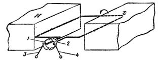
The beginning and end of the frame are each attached to its own collector plate. The brushes are arranged in such a way that one of them is always connected to the conductor that will move at the north pole, and the other to the conductor that will move at the south pole. On fig. 1. shows a general view of the collector of an electrical machine.
To consider the operation of the collector, let us turn to Fig. 2, in which the frame with conductors A and B is shown in section. For greater clarity, conductor A is shown with a thick circle, and conductor B with two thin circles.
The brushes are closed to external resistance then e. d.s., induced in conductors, will cause an electric current in a closed circuit. Therefore, when considering the work of the collector, we can not talk about induced e. d.s., but about the induced electric current.
Rice. 1. Electrical machine manifold
Rice. 2. Simplified image of the collector
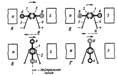
Rice. 3. AC rectification with a collector
Let's tell the frame a rotational movement in a clockwise direction. At the moment when the rotating frame takes the position shown in Fig. 3, A, the largest current will be induced in its conductors, since the conductors cross the magnetic lines of force, moving perpendicular to them.
The induced current from the conductor B connected to the collector plate 2 will go to the brush 4 and, having passed the external circuit, through the brush 3 will return to the conductor A. In this case, the right brush will be positive and the left brush negative.
Further rotation of the frame (position B) will again induce current in both conductors; however, the direction of the current in the conductors will be opposite to that which they had in position A. Since the collector plates turn along with the conductors, brush 4 will again give electric current to the external circuit, and through brush 3 the current will return to the frame.
It follows that, despite the change in the direction of the current in the rotating conductors themselves, due to the switching produced by the collector, the direction of the current in the external circuit has not changed.
At the next moment (position D), when the frame again takes a position on the neutral line, there will again be no current in the conductors and, therefore, in the external circuit.
At subsequent moments of time, the considered cycle of movements will be repeated in the same order. Thus, the direction of the induced current in the external circuit due to the collector will always remain the same, and at the same time the polarity of the brushes will be preserved.
Rice. 4. DC motor manifold
An idea of the nature of the current change in the external circuit during one revolution of the frame equipped with a collector is given by the curve in Fig. 5. It can be seen from the curve that the current reaches its greatest values at the points corresponding to 90 ° and 270 °, that is, when the conductors cross the lines of force directly under the poles. At the points 0° (360°) and 180°, the current in the external circuit is equal to zero, since the conductors, passing the neutral line, do not cross the lines of force.
Rice. 5. Curve of current change in the external circuit for one revolution of the frame after rectification by the collector
It is not difficult to conclude from the curve that although the direction of the current in the external circuit remains unchanged, its magnitude is constantly changing from zero to a maximum.
An electric current that is constant in direction but variable in magnitude is called a pulsating current. For practical purposes, pulsating current is very inconvenient. Therefore, in generators, they strive to smooth out ripples and make the current more even.
Unlike generators, in DC motors, the collector acts as an automatic current direction switch in the rotating armature conductors. If in the generator the collector serves to rectify alternating current into direct current, then in the electric motor the role of the collector is reduced to distributing the current in the armature windings in such a way that during the entire time the electric motor is running in the conductors currently under the north pole, the current passes constantly in which - either in one direction, and in conductors under the south pole - in the opposite direction.
electricalschool.info
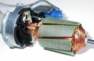
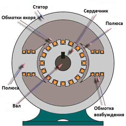
DC motor design
As you know, a DC motor is a device that, with the help of its two main structural parts, can convert electrical energy into mechanical energy. These key details include:
- stator - a fixed / static part of the engine, which contains the excitation windings to which power is supplied;
- rotor - the rotating part of the engine, which is responsible for mechanical rotation.
In addition to the above-mentioned basic parts of the DC motor design, there are also auxiliary parts, such as:
- collar;
- poles;
- excitation winding;
- armature winding;
- collector;
- brushes.
 DC motor design
Together, all these parts make up the integral design of the DC motor. And now let's take a closer look at the main parts of the electric motor.
The yoke of a DC motor, which is mainly made of cast iron or steel, is an integral part of the stator or static part of the motor. Its main function is to form a special protective coating for the thinner internal parts of the engine, as well as to provide support for the armature winding. In addition, the yoke serves as a protective cover for the magnetic poles and field winding of the DC motor, thus providing support for the entire excitation system.
The magnetic poles of a DC motor are body parts that are bolted to the inner wall of the stator.The design of magnetic poles basically consists of only two parts, namely, the pole core and the pole piece, which are joined to each other under the influence of hydraulic pressure and attached to the stator.
Video: Design and assembly of a DC motor
Regardless, the two parts serve different purposes. The pole core, for example, has a small cross-sectional area and is used to hold the pole piece to the yoke, while the pole piece, having a relatively large cross-sectional area, is used to propagate the magnetic flux created over the air gap between the stator and rotor to reduce magnetic loss. resistance. In addition, the pole piece has a plurality of excitation winding grooves, which create the excitation magnetic flux.
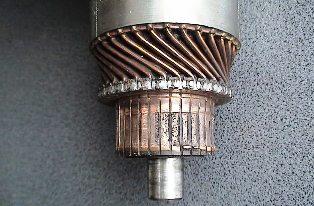
graphite brushes
Tool. There are no trifles in it. Manufacturers strive to reduce the cost and simplify designs to the limit. More and more synthetic materials, substitutes, analogues, etc. are being used. But there is an irreplaceable part in a power tool - brushes. They will be discussed.
It would seem - what is it about them? A piece of coal or graphite substance. But not everything is as simple as it seems at first glance. Let's start from the very beginning - why are they even needed - brushes in a power tool?
Brushes are essentially a current lead. Removes voltage from the stator and transfers it to the armature/rotor collector. An electric current passes through the brushes. Plus, the brushes experience mechanical stress during the rotation of the armature. There are also certain requirements for them, non-compliance with which can lead to very sad consequences. In order to more clearly imagine these possible consequences, as well as to understand the intricacies of the brush assembly in general, we will consider the characteristics of the brushes and the actual collector copper.
Brushes are formed mainly from graphite or carbon with the addition of various impurities. Here are the main types of brushes:
1. Coal.
2. Graphite.
3. Carbon-graphite.
3. Copper-plated.
4. Copper-graphite.
5. Copper-coal.
Brushes are hard and soft
This is important, as the armature collector copper is also soft and hard. If you install “hard” brushes on a “soft” collector, the collector will wear out quite quickly, which will lead to expensive repairs - replacing the armature
If you put "soft" brushes on a "hard" collector - the brushes will fail very soon - the copper of the collector will simply "eat" them
The brushes also have the so-called "active" resistance. This is taken into account when calculating the characteristics of the motor winding and the ratings of ballasts (soft start devices, speed control devices, etc.)
The brush knot is also not an easy task. It consists of a guide profile, a clamping device and a contact group. There are also non-contact brush holders, but they are mainly used for low-class tools and are quite rare. The most important element is the brush clamp. Pressing more than necessary leads to heating of the collector and brush assembly, which entails the failure of the armature. Insufficient pressure is increased sparking on the collector, and, as a result, failure of the armature and brush assembly, not to mention the fact that a weakened spring can jump off and do things inside the motor housing, cutting, for example, the stator winding or anchors - this can lead to a short circuit in the circuit and engine failure.
Professional, industrial and industrial power tools are equipped with brushes with an automatic shutdown device. The principle of operation of this device is simple. A spring with a ceramic non-conductive tip is mounted in the body of the brush.When the brush is worn to a certain limit, the tip is released and the spring pushes it onto the collector. The circuit opens and the engine stops. Brushes without such a device are dangerous because they work to the “victorious” (from the word “trouble”) end. With maximum wear, both the brush holder spring and the brush leash can get on the collector - this can lead to failure of the armature. To avoid such a nuisance, periodically check the condition of the brushes and the brush assembly. The wear limit is 2/3 of the original size of the brushes. There are also brushes with additional contacts that are necessary for the normal operation of power tool circuits. If there are such brushes in the tool, it should be noted that they can be changed ONLY for similar ones, otherwise the manufacturer does not guarantee the normal operation of the tool.
Now in many construction and tool specialization stores you can find departments offering brushes for various types of power tools. But there are nuances here too. We all know that our country is flooded with the dominance of "Chinese" and other counterfeit goods. This infection has also reached the brush market - counterfeiters always strive for demand market niches. The quality of most brushes available in the retail network leaves much to be desired. It is almost impossible for a non-specialist to identify a fake - there are too many nuances. So think about it - is it worth risking the "life" of the tool because of such a "little thing" as brushes? There are two ways to avoid mistakes when choosing brushes - this is their purchase from authorized dealers and the installation of brushes in a specialized service center, where, in addition to actually replacing the brushes, the master will check the general condition of the brush assembly and the power tool itself.
Catalog of brushes by types and sizes:
bobrenok-kos.ru
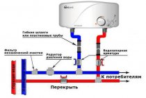
How to make a heating collector with your own hands: the nuances of technology
Approaching the issue of self-manufacturing a distribution manifold for heating, I immediately want to note that both units can be freely purchased at any specialized store - and this can be done both in a complex and separately (in the sense, buy each element separately). In the latter case, the collector is cheaper, but you will need to assemble it correctly. To further reduce the cost of these heating units, you can make them yourself, and this is not as difficult as it might seem at first glance. I also immediately want to note the fact that both of these units are made of different materials - the collector for the boiler room, due to its proximity to the coolant heater, must withstand very high temperatures, and therefore only metal is used for its manufacture. In contrast, a local distribution manifold can be made from any type of pipe, including polypropylene. Let us consider in more detail the technology of their manufacture.
- A collector for a boiler room - one cannot do without electric welding, even despite the simplicity of its assembly. A distribution manifold is made in three stages - first a hydraulic arrow is made (in fact, it is a piece of a pipe muffled on both sides and equipped with four nozzles, two of which are needed to connect it to the boiler, and the other two to connect distribution combs to it). Then, in turn, one after the other, the falling and reverse combs are made - in their design they are completely identical and may differ only in the direction of the conclusions. If they all look up, then you need to place them in a checkerboard pattern, i.e. on one of the combs, the nozzles must be shifted relative to the nozzles of the second collector. So it will be more convenient to mount the pipes.And at the third stage, the collector is equipped with everything necessary - these are taps, pumps, air discharge, as well as temperature and pressure sensors.
- A local distribution manifold is made in almost exactly the same way as a comb for a boiler room, except that it can simply be soldered from a polypropylene pipe or twisted from metal-plastic. It is better, of course, to solder - it will be more reliable. There is one “but” here - it concerns a polypropylene manifold. Due to the high cost of threaded limit switches, it will cost almost the same as the store. So here you should think about whether you need extra trouble or maybe it's easier to buy a ready-made collector?
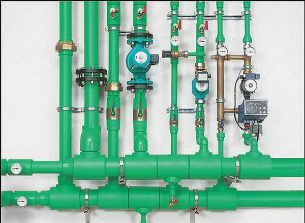
How to make a heating collector with your own hands
In principle, this is all that can be said about the independent manufacture of a distribution comb. By and large, it will not be difficult for a person who is familiar with plumbing work firsthand to make such a unit - especially if at least his drawing lies before his eyes.
And in conclusion, I will add only one thing - just like that, without appropriate calculations, it would be wrong to make a heating distribution manifold. Even in stores, they are sold in different sizes, and a clear calculation is needed here. In principle, a small power reserve, of course, does not hurt, but if there is a bust or, worse, a shortage, the heating system will significantly lose its efficiency.
CAUTION 2
паÑÑÑбки обÑединÑÑÑÑÑ Ð¾Ð±Ñим обÑим обÑим, пÑиÑоÐμÐ'инÐμннÑм к вÐμнÑиР»ÑÑоÑÑ 11, вÑÐ ± ÑÐ ° ÑÑвР° ÑÑим оÑиÑÐμннÑÐμ гР° Ð · Ñ Ð² Ð ° ÑмоÑÑÐμÑÑ ÑÐμÑÐμÐ · вÑÑл опнÑÑ ÑÑÑÐ ± Ñ.
a
|
аÑпÑеделение ÑкоÑоÑÑи в пÑÑке з г. a |
ÐоÑеÑи Ð´Ð°Ð²Ð»ÐµÐ½Ð¸Ñ Ð² вÑÑодном вÑÐ »ÐμÐ'ÑÑвиÐμ ÑÑÑÐ ± Ñл ÐμнÑноÑÑи, вÑÐ · вР° нной поÐ'воÐ'имой ÑÐ ± Ð¾ÐºÑ ÑÑÑÑÐμй, могÑÑ Ð ± ÑÑÑ ÑÑÑÐμÑÑвÐμннÑми, оÑоР± Ðμнно ÐμÑÐ »Ð¸ ÑÑÑÐ ± нÑй Ð Ð Ð Ð Ð Ð Ð Ð Ð Ð Ð Ð Ð Ð Ð Ð Ð Ð Ð Ð Ð Ð Ð Ð Ð Ð Ð Ð Ð Ð Ð Ð Ð Ð Ð Ð Ð Ð Ð Ð Ð Ð Ð μ1 Ð Ð Ð · ´Ð¾Ð»ÑкоÑоÑÑи коллекÑоÑе.
a
пÑеделение пÑоизводÑÑÑна обÑем вÑÑодном коллекÑоÑе игинаÑалÑном
a
ÑлÑÑае, еÑли обÑединеннÑй вÑÑодной коллекÑоÑ, Ð1 Ð Ð Ð Ð Ð Ð Ð Ð Ð Ð Ð Ð Ð Ð Ð Ð Ð Ð Ð Ð Ð Ð Ð Ð Ð Ð Ð Ð Ð Ð Ð Ð Ð Ð ° Ð Ð Ð Ð Ð Ð Ð Ð Ð Ð Ð Ð Ð Ð Ð Ð Ð Ð Ð Ð Ð Ð Ð Ð Ð Ð Ð Ð ² Ð Ð Ð Ð Ð Ð Ð Ð Ð Ð Ð Ð Ð Ð Ð Ð Ð Ð Ð Ð Ð Ð Ð Ð Ð Ð Ð Ð Ð Ð Ð Ð · Ð Ð Ð Ð Ð Ð Ð Ð Ð Ð Ð Ð Ð Ð Ð Ð Ð Ð Ð Ð Ð Ð Ð Ð Ð Ð Ð Ð Ð ÐμÐ Ð Ð Ð Ð Ð Ð Ð Ð ÐμÐ Ð Ð Ð Ð ÐμÐ Ð Ð Ð Ð Ð ÐμÐ Ð ÐμÐ Ð ÐμÐ Ð ² Ð Ð Ð ÐμÐ Ð ÐμÐ Ð Ð Ð
a
Таким обÑазом вÑÑодного в опÑÐμÐ'ÐμÐ »ÐμннÑÐμ момÐμнÑÑ Ð ± ÑÐ'ÐμÑ Ð · нР° ÑиÑÐμл Ñно оÑÐ »Ð¸ÑÐ ° ÑÑÑÑ Ð¾Ñ ÑÐμмпÐμÑÐ ° ÑÑÑÑ ÑÑÐμнки Ð · Ð ° вР° л ÑÑовР° нного в РРРРРРРРРРРРРРРРРРРРРРРРРРРРРРРРРРРРРРРРРРРРРРРРРРРРРРРРРРРРРРРРРРРРРРРРРРРРРРРРРРРРРРРРРРРРРРРРРРРРРРРРРРРРоðððððð½½½μμ½½ðñðññððññ½ñññññññ
a
ROOT вÑÑодномÑ. Рг Ð Ð Ð Ð Ð Ð Ð Ð Ð Ð Ð Ð Ð Ð Ð Ð Ð Ð Ð Ð Ð Ð Ð Ð Ð Ð Ð Ð Ð Ð Ð Ð Ð Ð Ð Ð Ð Ð Ð Ð Ð Ð Ð Ð Ð Ð Ð Ð Ð Ð Ð Ð Ð Ð Ð Ð Ð Ð Ð Ð Ð Ð Ð Ð Ð Ð Ð Ð Ð Ð Ð Ð Ð Ð Ð Ð Ð Ð Ð ²Ð Ð Ð Ð Ð Ð Ð Ð Ð ° Ð Ð Ð Ð Ð Ð Ð Ð Ð Ð Ð Ð Ð Ð Ð Ð Ð Ð Ð ² Ð ññððо Ð Ð ²Ð Ð Ð Ð Ð Ð ²
a
ÐÑоме неплоÑноÑÑей, на вÑÑодном Ð Ð Ð Ð Ð Ð Ð Ð Ð Ð Ð Ð Ð Ð Ð Ð Ð Ð Ð Ð Ð Ð Ð Ð Ð Ð Ð Ðμ Ð Ð Ð Ð Ð Ð Ð Ðμ Ð Ð Ð Ð Ð Ð Ð Ð Ð Ð Ð Ð δÐ Ðμ
a
|
300 Rbl. a |
ROOM вÑÑодном Ð · Ð ° коÑÐ »Ð¾Ð¼, нР° Ñол оÐ'ной и гоÑÑÑÐμй Ð »Ð¸Ð½Ð¸ÑÑ Ð¿ÑомÐμжÑÑоÑного пÐμÑÐμгÑÐμвР° пР° ÑÐ ° Ð'о Ð · Ð ° поÑнÑÑ Ð·Ð°Ð´Ð²Ð¸Ð¶ÐµÐº.
a
|
ÐомпоновкР° кÑÑпного Ð ° вÑомР° ÑиР· иÑовР° нного ÐÐ Ð Ñ ÑÐμгÑÐ »ÑÑоÑÐ ° ми ÑипР° ÐРРи Ñл ÐμкÑÑоннÑм ÑпÑÐ ° вР»Ðμни 180,000 Br / C. a |
ROOM: 7 — — вÑÑодной коллекÑÐ¾Ñ Ð´Ð°Ð²Ð»ÐµÐ½Ð¸ÐµÐ¼Ð³ 8 аÑна завод; S - вÑÑод газа: S-моÑÑовой однобалоÑнÑРкÑан.
a
|
Ð ÐμгÑÐ »Ð¸ÑовР° ниÐμ ÑÐ ° ÑÑоÐ'Ð ° Ñ Ð¿Ð¾Ð¼Ð¾ÑÑÑ ÑÑжР° ÑÑÐμго ÑÑÑÑойÑÑвР° 1 - вÑоÐ'ной ÑÑÑÐ ± опÑовоÐ' ÐÐÐ, 2 - вÑÑоÐ'ной кол Ð »ÐμкÑÐ¾Ñ , 3 a |
аÑÑмоÑÑим завиÑимоÑÑÑÐ¼ÐµÐ¶Ð´Ñ ÑкоÑоÑÑÑми в вÑÑодном и ÑÑÑбопÑоводе блока каÑеÑÑва.
a
кÑопеÑегÑеваÑели вÑÑодном и РРо Ð Ð Ð Ð Ð Ð Ð Ð Ð Ð Ð Ð Ð Ð Ð Ð Ð Ð Ð Ð Ð Ð Ð Ð Ð Ð Ð Ð Ð Ð Ð Ð Ð Ð Ð Ð Ð Ð Ð Ð Ð Ð Ð Ð Ð Ð Ð Ð Ð Ð Ð Ð Ð Ð Ð Ð Ð Ð ²Ð Ð Ð Ð Ð Ð ² Ð Ð Ð Ð Ð Ð Ð Ð Ð Ð Ð Ð Ð Ð Ð Ð Ð Ð Ð Ð Ð Ð Ð Ð Ð Ð Ð Ð Ð Ð Ð Ð Ð Ð Ð Ð Ð Ð Ð Ð Ð Ð Ð Ð Ð Ð Ð Ð Ð Ð Ð Ð Ð Ð ENGLISH PLASTING ENGLISH ENGLES R.
a