Water drainage along the perimeter of buildings features of planning and installation
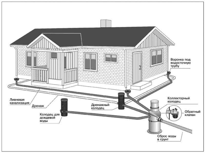
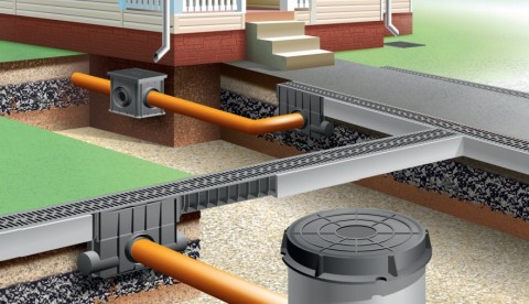
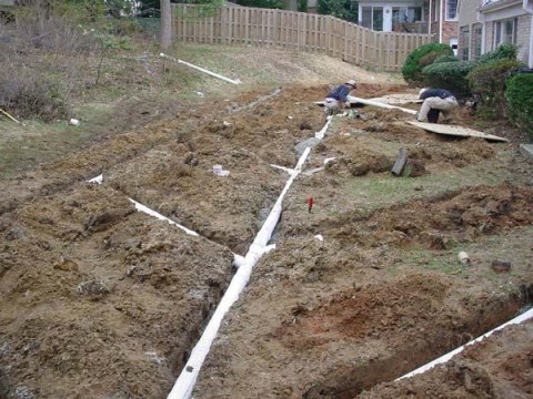
Surface drainage, which is installed around the house, is open lines along the perimeter of the foundation, connected at one point by an inspection well. From the connection point, the line is diverted to a receiving reservoir or collector.
Surface drainage network branch and point receivers around the house
When planning the trajectory of the branches, the highest point is chosen at a distance of up to 50 - 70 cm from the edge of the foundation. From this point, the channels will be dug with an inclination - to the point of installation of the revision well, in order to ensure free flow of water.
Moisture removal elements in the system around the house
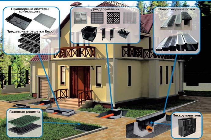
To install a surface drainage system around the foundation of the house, you will need:
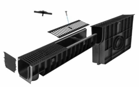
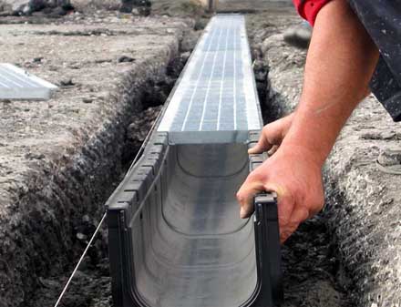
Trays with bars. There are products of different sizes. The main materials of manufacture are polymers, concrete. Plastic containers are suitable for mounting on decorative paths, blind areas. If you need to lay a branch at the entrance to a garage or house, it is better to use concrete trays with metal gratings, designed for a load of up to 25 tons. Ready-made containers are equipped with connecting elements that are fixed like a lock
Pay attention to the presence of spacers - they are installed in plastic trays
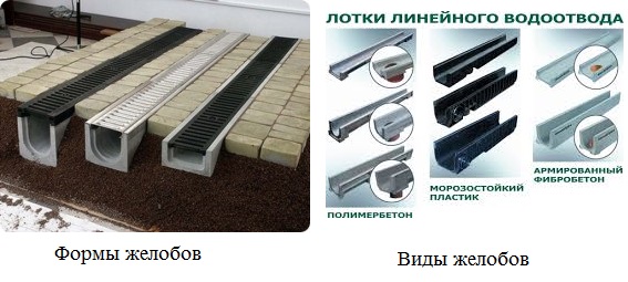
Types of gutters and materials of manufacture
Revision well. It is easier to install ready-made plastic parts. You can use concrete rings, or make your own revision of the concrete solution.
Tray connected to the outlet container
- Pipes for withdrawal.
- Bedding. Definitely gravel and sand. If you plan to install on a concrete base, you will have to prepare a mortar for pouring and draft boards to assemble the formwork.
- Earthwork tools and building level.
How to independently make surface drainage around the house on the site? The best way is to combine the installation of drainage lines with the arrangement of the blind area after backfilling the foundation. This approach will greatly facilitate the task - instead of digging out the channels, you can simply deepen the trays along the planned lines when backfilling and bring out a perfectly flat path, filling the blind area with concrete.
Installation height and possible direction of system lines
If you have to save a previously built house from moisture, then at a distance of up to 70 cm from the walls you need to make markings: hammer in the pegs and pull the tape or fishing line. You will have to dig channels to a depth of up to 50 cm. The slope in a straight line is up to 2 cm per meter. You can independently calculate the depth, guided by the hint on the diagram:

Tray lid - flush with stone
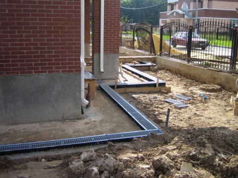
The bottom and walls of the ditches are strengthened: they are carefully rammed, sprinkled with sand, compacted and filled with gravel or gravel. To make the base airtight, experts prefer to make a monolithic concrete pad: the bottom is poured with mortar to the height of the bottom of the tray. Lines of connected gutters are installed on the prepared base. Check the integrity of the connections: the edges of the two containers should be at the same level. In order not to deviate from the horizontal line, a fishing line is pulled along the bottom.
Gutter installation
Covers are fixed on the installed trays. Check the height. If it is planned to lay tiles or stone, then the protrusion of the gutter from the ditch must correspond to the height of the decorative coating with a layer of fixing mortar.
The ledge of the gutter over the blind area prepared for laying the stone
It is possible to achieve an absolutely flat surface and at the same time give the correct slope to the blind area when combining the pouring with the installation of drainage. Gutters are laid on a gravel-filled base. Form a minimal slope from the wall of the house. A reinforcing mesh is installed on the backfill and the solution is poured.
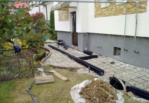
Simultaneous installation of drainage and filling the track
In an open surface drainage system around the house, at least one drainage well must be installed on the site. Pipes-branches connected to the sand traps are connected to the tank.
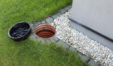
Drainage tank with blank cover
More revisions are not required. Flushing of pipes can be carried out through water collectors, and gutters are easily cleaned from the surface. The manhole is mounted at the lowest point - the place where all pipes of the surface network are supplied.
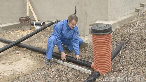
Pipe connection
Install the container on a bulk pillow. Branches are connected to the pipes, it is checked that the outlet pipe is located below the entry points of the drainage pipes. A layer of sand or fine gravel is poured between the walls of the installation pit and the outer walls of the container.
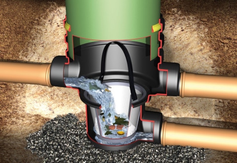
Drainage tank diagram
The discharge pipe is led into the storm sewer collector, or into a natural, artificial reservoir, moat.
Create a project
The quality of the design depends on how effective the drainage communications will be. The design of drainage systems takes into account the following points:
- The degree of susceptibility of soil-forming rocks to soil leaching;
- The value of the permeability of some types of soil;
- Presence of tectonic deformations;
- Groundwater structure;
- Location and power of sources feeding groundwater flows.
The design of the drainage system takes into account the following rules:
- The slope from the top of the pipe to the catchment devices is 0.5-0.7%;
- The system contains means for monitoring the operation of drainage and flushing devices;
- The bottom of the pipe is installed 20 cm below the foundation point (if the drainage is located next to the house).
It is desirable that the drainage system on the site have manholes. They are installed in the places where the pipeline turns. When designing, the calculation of the drainage system is also carried out.
Schematic project on a suburban area
Skilled summer residents perform drainage of the site with their own hands. Here you need to know that there are two types of drainage: surface and deep. The choice depends on the purpose for which the structure is being created. You can use drainage only near the house, so that soil does not wash out under the foundation. Another option is to create channels on the site to improve the landscape. The method is used when plants have too much water and swamping occurs (if there is a reservoir nearby or it rains several times a week).
V. Design of subgrade with complete excavation
36. The method of complete peat removal consists in removing weak soil from the base of the embankment to dense layers of the mineral bottom of the swamp with immediate filling of the excavation with high-quality imported soil. At the same time, it is necessary to comply with the condition that the sole of the embankment rests on the roof of dense layers with its entire area.
37. When designing peat, one should strive for maximum stability of the subgrade by creating the steepest slopes of the excavation. The slope angle of the excavation is assigned according to the data of field studies /p. sixteen/. The width of the bottom of the excavation should not be less than the width of the subgrade between the edges of the embankment.
In order to ensure the quality of peat removal, the mark of the bottom of the excavation should be set 10-15 cm below the bottom of the swamp.
38. If there is a longitudinal or transverse slope of the swamp bottom of more than 10%, the bottom should be developed in steps during mechanical peat removal, or in the case of unstable peat, a large stone should be thrown from the lower side / fig. a, b/.
With the explosive method of peat removal, the sloping bottom should be worked out with chisels / fig. v/.
39. Depending on the type of swamp and the amount of work, peat removal can be carried out in the following ways:
a) mechanical development;
b) ejection explosions;
c) blasting under an embankment;
d) hydraulic peat removal;
e) planting an embankment on the bottom of the swamp with extrusion of weak soil by the weight of the embankment.
Note: See SNiP III-D for instructions on the technology and organization of peat removal by various methods. 5-62.
40. In type II and III swamps, the subgrade, as a rule, should be constructed by squeezing out weak layers by the weight of the embankment being poured. At the same time, the requirement to support the entire sole of the embankment on the dense layers of the mineral bottom of the swamp must also be met.
If there are dense layers of peat in the upper part of the swamp, the latter must be removed or loosened by mechanical, explosive or hydraulic methods to the width of the subgrade plus two strips on each side with a width not less than the depth of the swamp. If the dense layers make up more than half the depth of the swamp, to facilitate extrusion, it is necessary to provide for the installation of peat inlets on both sides of the embankment. The volume of peat receivers must be at least half the volume of peat to be squeezed out.
The minimum height of the bulk layer required to extrude a weak layer is determined by the formula:
(7)
where:V - the width of the embankment at the base
WITH - adhesion of the weak layer
Hsl— power of the extruded layer
- volumetric weight of the soil of the embankment.
Use the plot feature
Since your site has a slight slope towards the road from the house, consider yourself very lucky. For the device of a drainage on your site the big labor costs will not be required. In your case, it is necessary to correctly combine open and closed drainage. Open drainage is equipped with open drainage ditches, which will perform the function of water outflow both in the spring-summer-autumn period and during winter thaws, when the frozen ground does not yet absorb water, and the surface outflow of excess moisture is already so necessary. For the device of such drainage, special tiles are used to drain water, which are laid at a slight slope, so that water from the roof and walkways gets to the main (closed) drainage system as quickly as possible. Closed drainage provides for the deepening of the drainage system underground, but a little more about this ...
Important!!! A few rules for the operation of the drainage system on clay soils:
- It is good to loosen dense heavy soil to improve culvert capacity.
- Do not lay drains in those places of the site where the car is planned to pass.
Creating deep drainage all ways to cope with the high level of groundwater on a summer cottage
The purpose of deep drainage is to reduce the amount of moisture in the soil. Installation of a deep-type drainage system is suitable for situations where the site is located in a wetland, lowland, next to a reservoir, and when it is planned to create a basement, garage, etc. under the house.
Traditional ditches are no longer suitable; special tools are required - drain pipes, rolled waterproofing.
The principle of operation of the simplest drainage: a drainage device using pipes
Moisture is collected in drains, from there - into the central pipe, and then through the catchment well it enters the water intake and water is drained from the site. Manholes are also considered additional equipment.
When creating drainage, it is necessary to organize high-quality moisture removal. The role of the water intake is performed by ditches along the road, ravines, rivers, sewer structures.
Depth measurement for installing drainage around a garden plot
The drainage system of the site is mounted below the level at which the ground flows flow. It is impossible to perform a measurement on your own, without the use of geodetic tools. It is advisable to contact professional hydrogeologists who will measure the depth and create a detailed soil plan, indicating the depth of groundwater flow.
If drainage on a land plot is required not to protect the foundation of the house from washing out, but to create conditions for vegetation, a simplified method of measuring depth is used.On mineral soil, channels are mounted at a depth of 0.6 - 1.5 m. For garden plants and lawns - up to 0.8 m, for forest, tall plants - up to 0.9 m, for trees - up to 1.2 - 1, 5 m. For a peat base, the depth of the ditches is 1 - 1.6 m, because peat tends to settle.
Varieties of pipes
Trench for laying a drainage pipe
To create a drainage structure, perforated pipes are used, with holes of 2-5 mm in size located on them. About 40 years ago, the pipeline for drainage was built from ceramics or asbestos cement. But the products immediately failed - the pipes had to be constantly washed so that no dirt remained inside.
Polymer pipe - a design made taking into account all the technical nuances. The pipe diameter is 50 - 200 mm, and some varieties are equipped with a filter mechanism that protects the drainage openings from clogging.
Creating the correct drainage of the site with your own hands according to the project
Installation of a deep-type drainage system is carried out as follows:
- Channels 0.4 m wide are dug (how to determine the depth is written above);
- The channels are alternately covered with sand and gravel;
- On this basis, a drainage pipeline is installed;
- The structure is covered with rubble and sand, while half of the depth of the canal remains;
- The trench is covered with loam of a dense structure;
- The last layer is fertile soil.
Manholes with open drainage
To control drainage and to clean the pipeline, manholes (round or rectangular) are created in the structure. They are made of reinforced concrete rings. If the drainage system on the site is located at least 3 m, PVC pipes (with a smooth or corrugated surface) with a diameter of 0.3 - 0.5 m are used. Wells do not require tightness and waterproofing, since their function is to control water flows and supply pressurized water to clean the pipeline.
The gaps between the wells do not exceed 50 m. In a high-quality structure, the wells are also located at the turns of the canals.
After the installation of the drainage, with properly executed construction, it is not visible on the surface and does not interfere with other objects. Draining the site, it catalyzes the growth of vegetation, prevents waterlogging and washing out of the soil under the foundation.
WATCH VIDEO
Common mistakes when creating drainage:
- The use of pipes that are not suitable for this soil. As a result, the pipeline becomes clogged. An example of an incorrect combination: drainage pipe without filter for clay soil;
- Installation of the pipeline directly into the ground, without the arrangement of sprinkles for filtration;
- Creation of incorrect slopes and irregular water intake from the well shaft;
Competent drainage systems for the removal of groundwater are a guarantee of a long service life of building materials, the foundation of buildings in the country and dense vegetation. The drainage of the site must be carried out in accordance with all the rules of SNIP, so that the design is as efficient as possible!
VI. Design of subgrade with partial excavation
41. An earth bed with partial peat should be assigned in the following cases:
a) if the density of the peat deposit increases with depth;
b) if at a certain depth of the swamp there is a layer of high stumpiness, which does not allow the use of other types of subgrade structures;
c) in order to accelerate the consolidation of the base.
The same requirements apply to a subgrade with partial peat removal as to floating embankments / Ch.
42. The minimum depth of replacement of peat with high-quality mineral soil should be such that the total thickness of the bulk layer from the top of the remaining peat layer to the design mark is not less than that required by Table. .
43. The stability of the base of the embankment against extrusion with partial peat should be checked according to the Gersevanov-Puzyrevsky formula:
where:Rwithout — the value of the specific load that does not cause plastic deformation of the base;
V - the width of the embankment along the base;
- volumetric weight of the material of the embankment;
is the volumetric weight of peat in its natural state;
hv — depth of peat removal;
j and C — angle of internal friction and cohesion of peat according to laboratory data.
44. The amount of settlement of an embankment with partial peat removal due to the compaction of the remaining layers of peat is determined in the same way as for a floating embankment / p. /.
45. The duration of the intensive settlement of the embankment due to the consolidation of the foundation soils is determined in the same way as for the floating embankment / p. 82/.
With partial peat removal, the base consolidation rate increases in proportion to the square of the ratio of the total depth of the swamp to the thickness of the removed peat.
Closed drainage algorithm for clay soils
1. The first stage in the construction of a closed drainage system is the determination of the location of the water intake, which can be a natural reservoir or a ditch along the road.
How to solve the problem of lack of a natural water intake? There are several ways to solve the problem of outflow of water:
- the device of an artificial reservoir, for example, a pond in a country house or a swamp;
- the device of deep ditches outside the site (of course, not to the detriment of the neighbors);
- arrangement of vertical shallow wells with subsequent automatic pumping of water using pumps.
2. Along the perimeter of the site, break through trenches with a depth of 1 - 1.2 m and a width of 35 - 40 cm to collect water under the pipes, bringing them to the water intake. Let's call them "Main Channels". It is advisable to lay pipes with a diameter of 110 mm in the main channels. The main pipe is laid a little deeper than the collecting pipes of the drainage. According to regulatory documents, the drainage system is located no closer than 0.5 m from the fence and 1 m from the blind area of the house.
3. Water enters the main canals through drainage trenches. Dig a network of trenches 0.8–1.2 m deep and 30–35 cm wide for collecting drainage pipes on the site. The trench network device provides for the laying of small channels at a slope of at least 3-5 cm per linear meter. Thus, a normal flow is ensured, with a smaller slope, the flow rate decreases and stagnation of water in the area may be observed. The distance between drains in areas with heavy clay soils is approximately 7-10 m.
4. When the entire network of trenches has been dug, you need to leave it open and test it. Ideally, heavy rain is suitable for this, but if this is not expected in the near future, you need to shed the channels well, see how and at what speed the water flows and whether it stagnates. If necessary, problems must be eliminated, namely, to increase the flow rate - increase the slope or diameter of the pipes, in case of stagnant water - increase the density of the branching of the network of drainage channels.
5. After such a check, the pipes can be safely closed. To do this, line the dug channels with geotextiles that pass water well, such as non-woven fabric. On heavy clay and loamy soils, special volumetric drainage filters are especially effective, which not only protect the pipe from silting, but also improve water flow. Such filters are made from porous organic materials - rye straw, coconut fiber or fibrous peat.
6. Lay the prefabricated pipes, leading them to the main channels. The most commonly used plastic corrugated and perforated pipes with a diameter of 63 mm.
7. Drainage pipes are connected to each other with special tees - fittings or crosses, wrapping them in geotextiles to prevent solid particles from entering the pipes.
8. Wrap the free ends of the pipes in several layers of geotextile, tightly fixing them with wire. Through the free ends of the pipes, excess water enters the drainage system.
9.Fill the pipes with loose material that passes water well. Experts advise using crushed stone, expanded clay, small stones, sand for this. But I would advise using only coarse-grained sand, since it not only passes water well, but also does not clog the site during repair work. The backfill layer on the side and top is at least 15 cm.
10. The resulting sandwich of geotextile, pipe and sand is overlapped with the free edges of the geotextile and again covered with coarse sand.
Natalia Vysotskaya, landscape designer, Ph.D. -X. Sciences
2013 – 2014, Planting a Garden. All rights reserved.
Creating surface drainage in a site with clay soil
Surface drainage of the site is considered a good means to protect against waterlogging of the soil. For the construction of such a structure, trenches are not required. Drainage of the site is carried out using a tray or backfill method.
Do-it-yourself surface drainage is created as follows:
- Geoprocessing of the landscape is in progress, a layout of ditches is being created;
- Trenches are dug 70 cm deep, 50 cm wide.
- The walls tilt depending on the type of soil, the standard slope is 30 degrees.
If the backfill method is used, the recesses are filled with crushed stone to 2/3 of the depth. And on 1/3 crushed stone of a smaller fraction is poured. From above, the trench is covered with turf.
If the tray method is used, special trays are used to create drainage. The purpose of the products is the removal of rain flows, drainage water. Concrete drainage trays, polymer, PVC products, polymer concrete trays are produced.
Tray drainage is created as follows:
- A 10 cm trench is filled up and compacted with a sand mixture;
- Trays and sand and dust containment made of PVC material are installed on top;
- Grids are laid on the trays (so that debris does not fall inside, and the trenches look more aesthetically pleasing) or a special drainage tray with a grid is used.
Drain well device
Open and Closed Plot Drainage Network Budget Garden Drainage
With your own hands, it is much easier to make a simple open surface drainage of the site. Wiring diagram:
- A central line is chosen - a wide trench will be formed along it, to which side branches are brought.
- Make the marking of the side branches: at an angle of up to 45o to the main ditch.
Wiring diagram of the surface drainage network
The depth of the trenches is from 50 to 70 cm. Along the side branches, a slope of up to 2 cm per meter is made towards the main highway. The width of the ditches is up to 50 cm. It is advisable to expand the channels as you approach the main branch to facilitate the flow of water.
The walls of the trench are dug in such a way that a smooth slope towards the bottom is obtained - with an angle of up to 30 °. The bottom must be rammed. Further arrangement depends on the chosen type of organization of ditches - open or closed.
Open lines:
It is poured along the inner surface with a solution along the formwork: concrete channels are not washed out by water, are easy to clean and can last for decades.
Concrete drainage channel
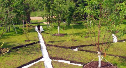
Filled with gravel over geotextile and left as dry streams and gravel strips along paths.
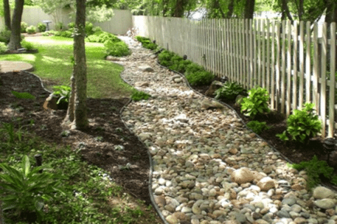
Aesthetic open line in the garden
The interior walls are lined with decorative stone.
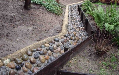
Lacquered stone on the walls
In closed trenches, a sandwich is formed from special materials: geotextile, crushed stone and, if necessary, perforated pipes.
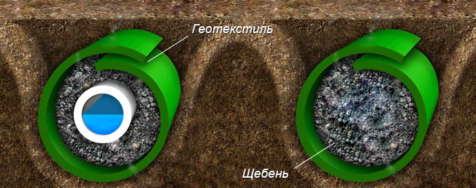
Closed line under the turf
Geotextiles are laid on a sand cushion so that the width of the free edges reaches 60 cm. A layer of crushed stone up to 30 cm thick is poured onto the canvas.
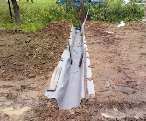
Linen laying
If pipes are to be installed, they are laid inside the gravel backfill. Wrap the canvas in the form of a roller, connecting the edges.
Sandwich: gravel in a wrap
A layer of sand or fine gravel is poured from above. The surface is covered with a layer of soil or turf with lawn grass.
The basic rules for arranging trenches and the problems that site owners face when installing surface drainage lines.
Installing the trays yourself according to the instructions is not a problem. No special tools are needed, all connecting elements and parts are prudently prepared by the manufacturer. Installation of plastic lines is simple. It is much more difficult to cope with the creation of a full-fledged branch on a large area with complex terrain. Problems start already at the planning stage. Earthworks take a lot of time, and in case of erroneous calculations, it may be necessary to lay new trenches. For the system to work for decades, entrust the planning and installation to specialists.
Drainage and drainage scheme
Taking into account the above characteristics, the choice of the type of drainage system is made, which can be surface, vertical and deep. Surface drainage performs the function of draining rain and melt water from the surface of the site
It is not difficult to design and install such a system. Since the drains are located on the surface, there is no need to calculate the depth of drainage, respectively, and the volume of excavation is insignificant.
Surface drainage performs the function of removing rain and melt water from the surface of the site. It is not difficult to design and install such a system. Since the drains are located on the surface, it is not necessary to calculate the drainage depth, and, accordingly, the amount of excavation is insignificant.
Vertical drainage is a system of drainage wells located in places where moisture accumulates the most. The collected water is discharged either into the lower layers of the soil, or pumped out using pumping equipment.
The deep system is most efficient, since it allows you to protect the territory from almost all sources of water supply. It is a network of drainage pipes, which are located at a certain depth. Such drainage is often used to protect foundations and basements, as well as the garden area from ground and ground-pressure supply.