Marking and types of trays for heating mains
The main document regulating the dimensions of tray structures is Series 3.006.1-2.87, it also describes their marking, consisting of the following sequence of alphabetic and numeric characters:
- L - tray, the plate that covers it is similarly designated (letter P);
- d - placed behind the first digit indicates additional products;
- numbers from 1 to 38 - indicate the serial number of the standard size and design of the product;
- The number behind the hyphen indicates the vertical pressure uniformly distributed over an area of 1 square meter (m2) in kilogram-force (kgf), but more often in ton-force (tf), which the product can withstand;
- a - the letter after the second digit indicates grades with steel tabs.
There is another Series 3.006.1-8 of working drawings and sizes of tray elements with holes, which has a different symbol. In it, alphabetic characters and numbers according to their positions mean the following:
- KL - tray, PTU - overlapping corner plate, PDU - corner bottom plate, PTO - plate with a hole, LKO - tray product with a hole;
- the next three digits indicate the length, width and height of the product in centimeters;
- the last number after the hyphen is the design load in tf/m2.
Structural and dimensional parameters of tray LK 300.180.120-6 from Series 3.006.1-8
From tray elements, underground structures are mounted, which are divided into two groups:
- channels - products having a net height of less than 150 cm;
- tunnels - engineering communications from trays with a height of 180 cm or more.
The marking of channels and tunnels has an alphanumeric designation by analogy with trays and consists of symbols:
- KL - tray channels covered with plates;
- KLp - channels of trays, which are based on plates;
- KLS - Structures of two reinforced concrete products, based on the ends of the side walls of each other.
The number after the letter indicates the width of the channel in centimeters, the next number is the height of the tray in centimeters. The numeric character after the hyphen is the workload in tf/m2.
Characteristics of trays of extreme standard sizes according to Series 3.006.1-2.87
III. INSTRUCTIONS ON THE ORGANIZATION OF WORK
Earthworks for excavation of pits under
sockets and trenches for tray blocks must be completed before installation work.
Blocks must be in advance
delivered to the place of work. Blocks are unloaded at the pit of the outlet bell
outlet bell and several tray blocks (depending on the overhang
crane booms). The remaining blocks of the tray are unloaded along the trench at the parking lots.
truck crane, and at the pit of the upper bell, the blocks of the upper bell are unloaded.
The blocks must be stacked so that they do not interfere with the passage of the truck crane.
Crushed stone for crushed stone preparation
unload at both sockets and intermediate stops.
Earthworks for trenching
the tray is performed by a link of workers consisting of: an excavator driver of the 6th category, and
diggers: 3 bits. - 1, 2 cuts. — 2.
The diggers work on the rough
planning trenches and pits after excavator work with digging trenches under
thrust spurs and under the stops, and then finally plan the bottom of the trench under the rail
with slope.
Installation of blocks is performed by a link consisting of:
truck crane driver 5 years and assemblers of structures: 4 cuts. - 1, 3 cuts. —
2.
During the work, the installer
designs 4 bits. instructs the truck crane driver to raise and lower
blocks, monitors their correct installation.
Structural assemblers, 3rd class. sling
blocks and direct them to the place of laying, and also arrange crushed stone
preparation.
For excerpts of trenches and pits, backfilling
sinuses primed with compaction and the final layout of the surface near the tray
involved: excavator driver 6 grade, compressor driver 4 grade. and
excavator 3 bit.
Dimensions
Trays are made of rectangular and trapezoidal shape with a slope of the inner walls. Their main dimensions are:
- the length according to the standard is 5970 mm, small concrete products of initial numbers have this standard size (at the discretion of the manufacturer, their length can be 2970 mm). Heavier large-sized products starting from numbers L25 (weight more than 5 tons) are produced with a size of 2970 mm for ease of transportation and installation;
- for all additional products with index d, a standard length of 720 mm is adopted;
- the width of the trays lies in the range from 420 mm to 4000 mm with the following gradation: 420 mm (L1); 570 mm (L2); 780 mm (L3 - L5); 1160 mm (L6 - L9); 1480 mm (L10 - L13); 1840 mm (L14 - L18); 2160 mm (L19 - L22); 2460 mm (L23 - L26); 2780 (L27 - L30); 3380 (L31 - L34); 4000 (L35 - L38);
- the height of the walls increases with increasing serial number and lies in the range from 360 mm for L1, L2 to 1700 mm for L38.
- wall thickness from 40 mm (L1) to 100 mm (L38);
- internal channel width - from 300 mm to 3600 mm;
- tray height from the inside from 300 mm to 1500 mm;
- bottom thickness - from 60 mm to 200 mm.
- the weight of the trays varies from 0.9 t for L1 with a concrete volume of 0.34 m3 to 9.38 t with a material volume of 3.75 m3 for L38.
- slabs of the KL and KLp types are produced with a length of 2990 mm, for reinforced concrete products with an internal width of 300 and 450 mm, the length of the slabs is 740 mm.
- for additional reinforced concrete products of 720 mm, the length of the overlapping slabs is 740 mm.
Scheme of installation of reinforced concrete channels
Production material
Trays are produced in accordance with GOST 13015.1-2003, in the normative act Series 3.006.1-2.87, working drawings are given and the following building materials are indicated, from which tray reinforced concrete products are made:
- the main component of their production is concrete of compressive strength class B15, B25, B30, B35, which corresponds to the strength grades of concrete M200, M300, M400, M450;
- reinforcement of class AI, AIII (GOST 5781-82), wire BpI (GOST 6727-80) is used for reinforcement;
- when arranging bookmarks, VSt3kp2 steel is used (according to GOST 380-71, this is structural carbon steel, V - supplied according to standardized chemical properties and physical parameters, kp - boiling, cn - calm, ps - semi-calm);
- anchor elements are made of class AIII steel (according to GOST 5781-82);
- for the production of mounting loops, steel of class AI grade VSt3sp2 or VSt3ps2 is taken. The use of the latter in temperatures below -40 ° C is unacceptable.
The trays are reinforced with frame and welded mesh elements according to the drawings and schemes for fixing reinforcement from Series 3.006.1-2.87, while the thickness of the protective concrete layer is taken equal to:
- with walls of a monolithic structure less than 10 cm - 1.5 cm;
- with walls of products more than 10 cm - 2 cm with a tolerance of +5 mm.
Reinforced concrete channel and tunnel elements according to Series 3.006.1-2.87 - parameters
Purpose
Reinforced concrete trays (ZhBL) for heating mains due to a wide range of standard sizes are used not only for their intended purpose, but also for other purposes, both in the household and in the construction, utilities, and industrial sectors.
Reinforced concrete trays for heating mains play the following role:
- They protect the water, gas, steam pipeline or cable from the physical pressure of the soil placed above it.
- They provide additional thermal protection of the pipeline, while saving money on heating water, steam or other coolant.
- Since the underground tray is covered from above with a protective cover and coated with waterproofing from the outside, moisture does not penetrate into it - in this way, internal engineering communications are protected from corrosion.
- Also, the reinforced concrete tray for the heating main does not allow the pipeline to come into contact with the soil, various biological organisms and animals. This increases the corrosion resistance of the pipeline and significantly increases its service life.
- A concrete tray for a heating main protects the pipeline from the physical impact of the soil during its subsidence, displacement as a result of earthquakes or erosion by groundwater.
- One of the popular uses for trays is to install them to drain various liquids. They can be used in the livestock sector of agriculture on livestock farms for the transportation of liquid manure, the organization of water supply channels. In land reclamation, trays are used for draining swampy areas.When conducting household out-of-town farming, using trays, you can supply water to the site from open sources, wells, standpipes, create channels for draining water from the territory.
Reinforcement schemes
The order of drainage from the separation lanes
The drainage of surface water from highway lanes, test sites and embankments exposed to groundwater is characterized by a list of individual characteristics. Most often, they are due to strictly individual contours of runoff directions in the plan, the presence of looped runoff areas and exits with large-scale multidirectional slopes, proximity and interaction with the city, etc.
drainage of water from trays
Branchings of transport arteries require the most efficient drainage of water and its redirection outside the roadway. Drainage systems must provide a stable, unhindered flow of liquid, directing it along the longitudinal slope in the required direction. If road junctions cross embankments, then special throughput pipes are used for drainage.
Installation and waterproofing of tray structures
Installation of channels and tunnels is carried out according to SNiP III -16-80 (Rules for the installation of prefabricated concrete and reinforced concrete structures) and SNiP III-4-80.
The basic rules for conducting work include the following points:
- Installation begins after the pillow is installed and the slopes and dimensions of the channel are checked with a construction tool.
- During installation, the trays are hooked to the hinges or use grips in the form of strong metal rods, passed into the opposite walls of the reinforced concrete products.
- When laying slabs, it is recommended to use tongs with friction grips without the use of hinges. Depending on the manufacturing technology of the plates, special holes in the products can be used for their installation; in the absence of loops and holes, sling loops are used.
- When laying the elements, the seams are filled with a cement mortar of grade 50; in places of deformation, the seam openings are filled with bitumen.
- If the laying is carried out by a semi-underground method, the seams between the ceilings are poured with bituminous mastic with a special filler according to SNiP III-20-74, which regulates roofing, waterproofing and vapor barrier work.
- All metal joints must be coated with an anti-corrosion compound, concreted in the tunnels according to the corresponding unit.
- Slinging holes after installation are covered with cement grade 50.
- It is allowed to install tray communications without upper and lower floors outside buildings with walls no more than 60 cm high, and in workshop channels with a depth of up to 50 cm.
- It is allowed to pull communications in open channel passages with no load during possible shedding of the earth or the absence of wall fasteners with temporary supports.
- In tunnels of a closed type, communications are pulled through mounting openings.
- Backfilling of the laid communications is carried out in evenly distributed layers 20-30 mm thick on both sides according to the excavation technology according to SNiP III-8-76.
- Installation of reinforced concrete products with backfill elements is carried out according to pre-applied marking risks.
Laying trays with special equipment
Waterproofing
When erecting flume engineering structures in areas with a high level of groundwater, the following methods are used to protect tunnel and channel structures from moisture:
- Arrange drainage, if its implementation is technically impossible, carry out hydraulic isolation. At the same time, the surface water level is considered to be 1 m below the level of the soil level with a deepening of up to 4.5 m and 1 m less than the top of the concrete goods with a deepening of more than 4.5 m.
- Hydraulic isolation on floors from groundwater penetration is carried out in accordance with SN 901-65, the prepared base for coating must have a slope of 4%.
- When laying, the following types of hydraulic insulation are used:
- cold from asphalt;
- hot from asphalt;
- pasting from bitumen;
- composite materials from acids, petrolatum, bituminous mastic.
- The outer surfaces of products outside the groundwater zone are coated with bituminous waterproofing. When laying heating networks for protection from surface water, it is guided by the relevant SNiP II-36-73.
- To increase the durability of reinforced concrete structures, reduce the complexity and cost of the work carried out, the use of waterproofing is recommended at a groundwater level of up to 20 m.
- The work is regulated by the instructions SN 301-65 (clause 2.1) and the requirements of SNiP 2.03.11-85 regarding the protection of building structures from corrosion under the aggressive influence of the aquatic environment.
- The waterproofing anti-pressure coating must be located at a height of at least 0.5 m above the maximum groundwater level.
- Prefabricated tray elements of channels and tunnels should be placed on a cushion of concrete grade 100 with a thickness of at least 10 cm, along the edges the preparation should be reinforced with meshes.
- If the preparation is carried out in an aggressive aquatic environment, it is performed from high-density concrete of a group of at least B6 in terms of water permeability.
- Another technology for creating a preparatory cushion in a trench is ramming crushed stone into the ground, followed by pouring it with bitumen until it is completely absorbed.
- Waterproofing units, expansion joints, protective fences, details of passage through the waterproofing layer of pipes, cables, must be carried out in accordance with SN 301-65
Tray cost
Widely used in industry, the construction industry, public utilities and agriculture, reinforced concrete trays for heating mains are produced for organizing open and closed channels, tunnels underground and on its surface. A significant number of standard sizes, availability, ease of installation, low price, significantly expand the scope of their application up to domestic use.
V. CALCULATION OF LABOR AND WAGES FOR THE DEVICE OF A CULVER 105 ms LONG WITH TWO SLEEVES
|
Code of rates and prices |
The composition of the link |
Description of works |
unit of measurement |
Scope of work |
Norm of time, man-hour |
rate, |
Norm- |
Full labor cost |
|
T-16, |
Driver 6 Assistant 5 |
Development |
100 |
0,57 |
6,6 |
4-92 |
3,76 |
2-80 |
|
ENiR, |
digger 2 |
Development |
m3 |
6 |
1,25 |
0-61,6 |
7,50 |
3-70 |
|
ENiR, |
digger 3 |
Bottom layout |
100 |
1,03 |
12,5 |
6-94 |
12,88 |
7-15 |
|
ENiR, |
Road 4 |
Device |
100 m2 |
0,1 |
14,5 |
8-09 |
1,45 |
0-81 |
|
ENiR, § 4-4-90, No. 3 b, as applicable |
Driver 6 Installers 4 |
Block assembly |
1 |
89 |
0,56 |
0-35,4 |
49,84 |
31-51 |
|
T-16, |
Driver 6 Assistant 5 |
layout |
100 |
3,27 |
1,22 |
0-91 |
3,99 |
2-98 |
|
ENiR,
2 a |
digger 3 |
Seal |
100 |
0,45 |
1,95 |
1-08 |
0,88 |
0-49 |
|
By the time |
Driver 4 |
Service |
man-hour |
0,88 |
1 |
0-62,5 |
0,88 |
0-55 |
|
Total |
81,18 |
49-99 |
VII. MATERIAL AND TECHNICAL RESOURCES
A. Main materials
|
Name |
Unit |
Quantity |
|
tray blocks |
PC. |
20 |
|
Blocks |
PC. |
4 |
|
Blocks for the input head |
PC. |
4 |
|
Plates |
set |
4 |
|
Stormwater |
set |
4 |
|
Tow |
kg |
12 |
|
cement mortar |
m3 |
0,6 |
|
rubble |
m3 |
4 |
B. Machinery, equipment and fixtures
|
Name |
brand, |
Quantity |
|
Truck crane |
K-64 |
1 |
|
Excavator |
E-4010 |
1 |
|
shovels |
GOST 3620-63 |
4 |
|
Scrap steel |
GOST 1405-65 |
3 |
|
Roulette type |
GOST 7502-69 |
1 |
|
Shurovki |
ZNIIS |
2 |
|
caulking |
GOST 11618-65 |
2 |
|
Slope Test Templates |
— |
2 |
|
hemp cord |
— |
40 m |
|
Four-line grab |
— |
1 |
|
Ropes 3 long |
— |
2 |
|
Rammer |
— |
1 |
|
Steel sheet (strike) |
— |
1 |
|
Compressor |
ZIF-55 |
1 |
Types of concrete trays
Concrete trays are made by pressing the source material, which gives additional strength to the product. In some cases, to give additional strength, metal particles are added to the concrete. Reinforced concrete drainage trays have a higher cost than conventional concrete products. Therefore, they are used exclusively in cases where increased strength is required.
Device and main characteristics
Galvanized steel rails are cheaper options than aluminum rails and they also provide some protection against oxidation due to the zinc on its surface. However, its disadvantage is the fact that this protection must be reinforced from time to time, presenting somewhat less effectiveness.
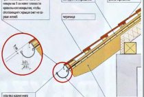
Step by step rail installation
The initial process of installing gutters is to measure structures and determine the direction of water flow. To do this, simply observe the roofing of your roof and measure, with the appropriate tools, all the compliments of the roof limits where the gutters will be installed later. Next, you need to determine the location of the nozzle, that is, where the pipe will be installed, which will drain the water from the roof to the ground. The most recommended locations for installing nozzles are where there is no foot traffic and near drains or other flow systems. Once determined, it will be necessary to cut the trim to the gutter, and this trim is usually done at two millimeters per metre. Soon the process of marking the supports that will have the gutter support function begins. The brackets vary depending on the type of track, but the recommended distance between them is between 50 centimeters and 1 meter. Please note that this is not a rule, but a recommendation, and there may be discrepancies between the measures shown here and those determined by the responsible professional. Then install the supports that will receive the gutter
It is important that special fastening materials are used, such as bolts, wall-type bushings, and supports that are strong enough to withstand the flow of water. Holes should be made on the wall with a drill to install the bushings, and then the brackets will be fixed with screws
Then amendments should be made when necessary. In some types of gutters, splicing may not be necessary, but if present, it is important to do it correctly. Therefore, according to the cutting direction, overlap the parts so that the water flow does not directly hit the seam, because over time, contact with water can break the connection and damage the gutter. Then install the gutters and accessories. With proper preparation, simply place the chute in the appropriate place, holding it in the most comfortable way, depending on the type of chute. Also install the material accessories so that the entire system is ready to go at the end of this step. And finally, the end of the service. The constant flow of water can damage the structure, and this is natural. To minimize the impact, you can use gutter protection products depending on the type of gutter.Contact your supplier and ask about suitable measures for your type of gutter.
Frequently Asked Questions About Gutters
Troughs are structures installed at the edge of a roof to bring rainwater to a more convenient location, bringing a number of benefits and conveniences to the consumer.
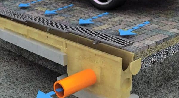
Concrete storm sewer trays can be classified according to the class of load that they can withstand:
- Class C250 is used on highways, the traffic intensity of which is characterized as low or medium, as well as in the area of arranging small parking lots intended for parking cars.
- The D400 class is used on high traffic roads, in the area of gas stations, garages and in small industrial areas.
- Class E600 is designed for drainage from highways, large industrial enterprises and railways.
- Class F900 has the highest strength and is used for drainage from airports, ports and large logistics centers.
In domestic construction, polymer concrete drainage trays are used (they cost less than concrete ones) or concrete class C250.
All concrete trays can be divided according to their parameters. Currently, trays are produced with a standard length of 1 m and various internal sections, which can vary from 100 mm to 500 mm.
How to make a tray Step by step instructions.
If you decide to make a drainage tray with your own hands, then you should act in the context of the following scheme:
You should start by preparing the molds for pouring. Contrary to popular belief, they can be not only metal, but also polymer
It is extremely important to carefully treat the inner walls of the form with machine oil. After lubricating the mold, it is necessary to fix the reinforcement in it;
The parts of the reinforcement should be fastened not only relative to the shape, but also relative to each other
As a rule, this stage of work is carried out using gas or electric welding.
It is necessary to fix the molds even before the start of pouring, even a slight mobility of the selected containers is considered unacceptable and may not affect the quality of the finished product in the best way.
After a week, you need to carefully pull out the formed channel from the pipe, if necessary, cover it with a layer of paint or any anti-corrosion compound that does not differ in roughness after drying. This will help increase the efficiency of the sewer due to the smooth internal structure.
In this video - a handicraft method of manufacturing
Even with total observance of the described technology, the service life of a tray made at home can differ significantly from the period of operation of a factory product, which is logical in itself. However, if you follow the described scheme, then the tray you made will not be inferior to the one that was manufactured in the factory in terms of efficiency in the process.
We look at how to make a U - shaped block for water drainage
Roads for cars and auxiliary units on their territory are seriously affected by the destructive effects of precipitation and other atmospheric factors. Precipitation in the form of rain seriously changes the mode of operation of roads, so their effective and timely removal plays a fundamental role.
The maximum harm to the stability of the structure is provided by the so-called. free water. The operation process is accompanied by significant fatigue of road surfaces, destruction of expansion joints, and the appearance of cracks. In order to delay this process as much as possible, drainage structures are used.
II. INSTRUCTIONS ON THE TECHNOLOGY OF THE PRODUCTION PROCESS
Tray arrangement includes the following
works:
- excavation of pits under the entrance and
outlet sockets and a trench under the tray by an excavator with manual cleaning;
— device for crushed stone preparation under
sockets and intermediate stops;
– installation of tray blocks and sockets
truck crane;
- filling the sinuses with soil and planning
slope in the tray area by an excavator with soil compaction.
Excavations for sockets and trenches for
the tray is torn off by an excavator on a car, equipped with a reverse
shovel with manual cleaning.
Soil excavated from pits and trenches
unload behind the outer edge of the tray, and when the tray is arranged in the cuvette of the recess
the excavated soil is loaded onto a dump truck and transported to a cavalier.
After manually cleaning the bottom of the trench
plan under the rail so that it has a design slope. At the bottom of the trench do
breakdown of the position of the thrust spurs of the tray blocks and tear off the transverse
trenches. With trays of great length, every 10 blocks are torn off
trenches for stops. For blocks of stop sockets and intermediate stops of the trench
should be torn off 15-20 cm wider for
possible regulation of the position of the block in the plan. At the entrance and exit
sockets, slopes must be planned for the installation of socket walls.
Crushed stone preparation layer 10
see do
under the upper and lower sockets and under the stop blocks, aligning the crushed stone under the rail and
compacting it with a hand rammer. After crushed stone preparation
check the level marks of its surface.
Tray installation starts from the bottom socket
(Fig. 2), install blocks of stops with the help of a truck crane, they are laid on them
socket tray plates, and then install the walls of the socket.

Fig. 2 General view of the tray from telescopic
blocks:
1 - crushed stone preparation; 2 - bottom thrust
input head block; 3 - top
thrust block of the input head; 4 - telescopic blocks; 5 - input
socket walls, 5 - tray plate of the inlet socket, 7 - outlet socket
walls, 5 - thrust blocks of the outlet bell, 9 - plates of the tray of the outlet bell
After checking the position of the blocks, the seams between
they are filled with cement-sand mortar.
The first block of the tray is slinged in four
mounting loops, served by a truck crane to the trench, lowered to height 1
m above
soil and deployed along the longitudinal axis. Then the block, holding the canopy, is injected
narrow end into the lower socket until it stops, while the stop spur of the block should
fall into a prepared trench.
The following blocks with a narrow end are inserted into
the end of the previous block to the stop and lowered to the bottom of the trench.
Before Installing the Last Tray Unit
install the lower thrust block of the upper socket and, after straightening it,
install the last block of the tray so that the stop spur of the block enters the groove
persistent block.
After installing all the blocks of the tray, produce
final alignment of the blocks using a truck crane, and then collect the top
trumpet. First install the upper thrust block, then lay the slab
the tray and the wall of the socket, fill the seams between them with a cement-sand mortar.
Backfilling of the sinuses between the tray and the slopes
trenches are made with an excavator equipped with a scraper. Following the backfilling of the sinuses
compact the soil with a pneumatic rammer.