Preparatory work
Before you make a distribution heating manifold with your own hands, you need to stock up on tools and perform a series of calculations - determine the length of the comb, the number of heat supply circuits and the internal section of the connected pipes
It is important that the hydraulic balance is observed in the design.
To do this, you need to make sure that the throughput of the collector nozzles corresponds to the sum of the same characteristics of the connected circuits. This is the key to the reliability and durability of the collector.
 The correct calculation of the heating collector can be carried out independently using special programs, or using the services of heat engineers. It is worth taking the calculations scrupulously, since their correctness will determine the correct assembly of the collector.
After making the calculations, the owner of the house should prepare the following components:
Also, the process of self-manufacturing of the collector provides for the presence of a certain tool for work:

Piping options
The main pipe laying patterns during installation are zigzag and spiral volutes, the latter provides more uniform heating and is considered the best in efficiency. When laying pipes, a certain distance between the sections should be maintained, it depends on the layout scheme and the thickness of the screed, its typical value for the usual thickness of the cement-sand layer lies in the range of 150 - 200 mm.
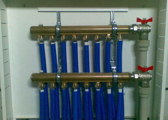
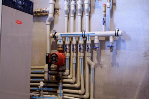
The distribution manifold is the main unit in an individual heating system containing two or more underfloor heating circuits, it performs the functions of distributing and mixing the coolant to reduce its temperature. During installation, a pipeline made of cross-linked or heat-resistant polyethylene is placed under the screed in the form of a zigzag or volute and connected to the combs using Eurocones, which provide a quick and tight connection.
Water gun and solar collector
A hydraulic arrow and a solar collector are devices that perform functions similar to water combs - they collect media from several sources in one housing and distribute it along circuits for various purposes.
A hydraulic distributor is installed in cases where significant volumes of coolant are used for heating, associated with a large number of circuits and areas of heated premises. A boiler, a hydraulic accumulator, collectors of heating radiators and underfloor heating, a boiler, pumping equipment with the installation of a circulation pump for each collector link are connected to the standing hydraulic arrow.
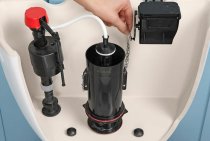
The device is designed to stabilize the pressure and equalize the temperature in the connected circuits, and ensures the convenience of connecting distribution units. A hydraulic arrow is a vertically (sometimes horizontal installation is used) located container (large-diameter pipe) of round or rectangular cross-section with welded side fittings, in the upper part of which there is a valve for de-airing, and a valve for draining the coolant is mounted below.
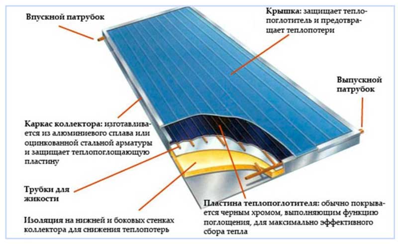
Rice. 12 Flat plate solar collector
Solar panels are used in areas with a large number of sunny days per year, and to save energy, solar collectors are used to additionally heat the coolant used for heating and other household purposes.
If solar panels convert ultraviolet radiation into electrical energy, then solar collectors are designed to heat the coolant, which is air or liquid.
The simplest and most popular collector device in everyday life is designed and works as follows. A heat receiver is placed in a metal case under the protective glass - a black plate with a pressed coil made of copper or aluminum coated with a black absorbent, the solar radiation receiver is located on the insulation layer. The cooled coolant moves along the coil with the help of the circulation pump of the heating system and, after being heated by solar radiation, enters the boiler.
The described system has high heat losses, therefore, in more expensive schemes, a pipeline covered with an absorbent layer is used, placed in a vacuum. Externally, the device resembles a series of glass flasks with evacuated air, inside which are placed heated copper pipes with refrigerant, each pipe is connected to a distribution solar collector. In such systems, a special refrigerant with a low boiling point is used as a coolant; when heated, it turns into steam and transfers its energy to the carrier flowing in the heat exchange manifold.
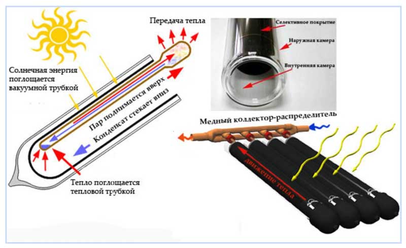
Fig.13 Vacuum solar collector - principle of operation
Solar collector saving opportunity
It is possible to connect several heat carrier heating sources to the heating circuit. Often solid fuel boilers operate in parallel with electric ones. this allows you to maintain the mode of operation of the heating system at night or in the absence of the owners for several days.
But such a regime cannot be called economical - electricity is one of the most expensive resources. Modern developments make it possible to use solar energy for heating the coolant by installing a solar collector.
A solar collector is an installation that can be used all year round even at cloudy temperatures. On sunny days, it is most efficient and heats up to the temperature of the boiler supply circuit - up to 70-90 degrees.
Homemade solar collector
The solar collector is a fairly simple device, it is not difficult to make it yourself. In terms of efficiency, a home-made solar water heater may be inferior to industrial models, but given their price - from 10 to 150 thousand rubles, a do-it-yourself solar collector will very quickly justify itself.
For its manufacture you need:
- a coil made of a metal tube, usually copper, you can take a suitable one from an old refrigerator;
- cuttings of a copper pipe with a thread of 16 mm on one side;
- plugs and valves;
- pipes for connection to the collector node;
- storage tank with a volume of 50 to 80 liters;
- wooden planks for the manufacture of the frame;
- expanded polystyrene sheet 30-40 mm thick;
- glass, you can take window glass;
- aluminum thick foil.
The coil is freed from freon residues by washing it with a stream of running water. From a wooden slat or bar, a frame is made with a size slightly larger than the coil. Holes are drilled in the lower part of the frame for the output of the coil tubes.
On the reverse side, a sheet of polystyrene foam is attached to it with glue or screws - this will be the bottom of the collector. This material has excellent thermal insulation characteristics, which will help reduce heat loss.
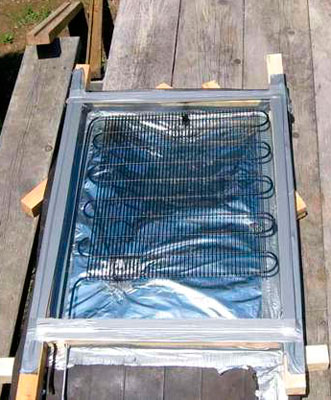 From the inside, the foil is laid so that it completely covers the bottom and walls of the frame. The foil is attached to the brackets with a stapler. A coil is placed in the frame, its ends are threaded into the hole.
The top of the solar collector is covered with glass, fixing it on glazing beads or rails. Pipes are attached to the ends of the coil for connection to the heating manifold assembly. This can be done using adapters or flexible piping.
The collector is placed on the southern slope of the roof. Pipes lead to a storage tank equipped with an air valve, and from there to a heating distribution manifold.
Video: how to make a solar heater yourself
A collector heating system is the most efficient way to connect various heaters to one or more heating sources. With it, you can ensure a stable temperature and comfort in the house, as well as uninterrupted and coordinated operation of all elements of the system.
What distribution combs are
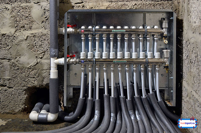
Manufacturers offer many models of collectors. Among them you can find devices with the maximum set of elements. The supply part is equipped with flow meters that regulate the flow of coolant in each loop, for a more even distribution. Thermal sensors are mounted on the return line to control the temperature of each heater. The system allows you to automatically control the heating of each radiator. The cost of such a heating distribution comb is quite high.

Collector block with the maximum set of functional elements. The supply part is equipped with flow meters that regulate the supply and pressure of the coolant. Thermal sensors are installed on the return manifold
You can choose more simple options. For example, a brass element with an inch passage. The device has plugs on the return manifold, which allows you to install additional devices if necessary. There are cast parts and the simplest ones - with collet clamps for metal-plastic pipes. This is the cheapest and most problematic option. The device often “suffers” from possible leakage of the coolant at the valve connection area, which is associated with the rapid wear of the seal, which can not always be changed.
Craftsmen often make distribution combs on their own. Perhaps the best option of all can be considered a stainless steel pipe of the desired diameter, to which the outlets are welded. But, despite all its simplicity, it is quite an expensive pleasure. And not only because of the cost of the pipe. You will need to install a lot more additional elements to get full-fledged equipment. Therefore, many use the most budgetary option - a heating manifold assembled from polypropylene tees, the desired size of valves, etc.
The most accessible and inexpensive collector. Self-assembled from polypropylene tees, valves of the right size, pipes and other necessary parts
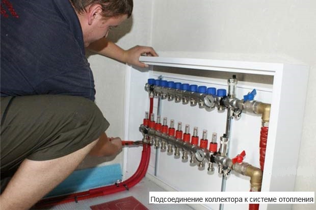
Do-it-yourself distribution manifold
If you have a small house, then it is quite possible that a factory manifold will suit you. But most of the time, this doesn't happen, and many people don't know what to do about it. Having suffered and tormented, they hire a plumber who does everything directly from the boiler. And then they complain that there is no heat.
After drawing up the estimate of the collector, we purchase the material, prepare the tool and proceed to the manufacture of the collector.
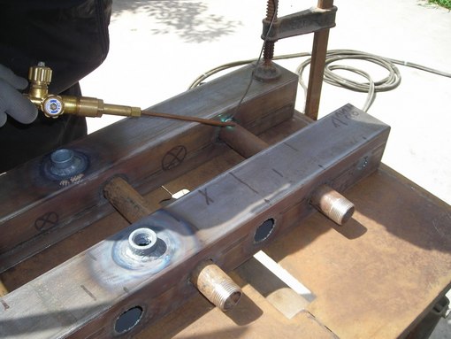
First, we clean the pipe square or pipe for the collector from rust. We make markings using a caliper, ruler and core.
We weld pipes and threads and weld fasteners.
Thus, it can be difficult or even impossible to choose a factory-made distributor for your specific conditions, since the size of the manifold and the size of the manifold nozzles are limited by the model range.
Consider drawing a collector circuit on the most common collector model in six circuits. First, we draw the supply and return manifold itself.
The coplanar distribution manifold in one fell swoop solved the problem of the number and size of connecting boilers and heating circuits, the problem of piling up pipes was solved and it became very fast and easy to monitor, maintain and repair boiler equipment.
The coplanar collector has a fairly simple device, so it will not be difficult to make it even for beginners who have not taken on the assembly of such devices before.
Learn more about installing self-heating cable in water pipes.
The distribution manifold is a metal comb with many branch pipes, which are designed to connect all heating devices in the premises for the purpose of central heating, the possibility of adjusting the temperature, the degree of supply of the coolant and pressure.
If the house has more than one floor, then the craftsmen install one distribution manifold per floor. In this way, high-quality heating is ensured in each room on the floor, and if repairs are necessary, a certain room or floor can be turned off, while other rooms or floors remain heated.
Now consider the principle of action in several stages:
On the Internet, it is quite easy to find diagrams for self-assembly of distribution manifolds, and at the same time there is not enough information about the specific steps required to assemble this device. Note that the reader, who decides to independently assemble the wiring, must first draw up a sketch, according to which further work will be carried out.
Drawing an analogy, it is a system of conductors and connections with centralized control for heating regulation.
We recommend that you familiarize yourself with the video, which tells how to make wiring for water with your own hands:
To date, one of the most profitable and acceptable options for the most productive operation of the heating system is the use of a distribution manifold, which allows you to evenly distribute the heat flows of the carrier over the entire surface. Given the features of the collectors, their properties and characteristics, this article will be devoted to these devices.
All working circuits will be connected to two devices - supply and return; this means that you, as a craftsman, will need to assemble a simple coplanar collector, the device of which we described above. When the sketch is ready, it remains to assemble the collector.
The second wiring is necessary to adjust the water pressure and the intensity of heating - with its help you can set the required pressure level on each branch.
Supply and return manifold device
Combs are one of the main elements of the collector circuit, their main function is the distribution of the coolant flow along the heating circuits. The element has a different design for lines of connected radiators and underfloor heating, the maximum number of involved circuits per collector does not exceed 12.
In relation to the diameters of the outlet fittings, the comb has a large cross section (1.1 1/2 inches vs. 3/4) and is connected to the line through an end connection with plumbing fittings. Usually, the pipeline is connected to the outlet fittings using compression fittings (Eurocones) - this method can be used to connect pipes made of cross-linked and heat-resistant polyethylene, metal-plastic, most commonly used in collector heating systems. Combs are made of stainless steel, brass, plastic, some modifications are assembled from separate links.
Material selection
 Before making the first blank, the owner of the house must study in detail the scheme for manufacturing the collector. It contains information about the material for the manufacture of the collector and its specification. At the same time, preference is given to durable, reliable and stable materials.
You can choose a durable metal as a material, such as steel, brass, copper. Also, the owner can choose polymers as materials and make a polypropylene heating manifold with his own hands from pre-purchased pipes. It should be understood that the polymer collector has a number of features.
A do-it-yourself manifold made of polypropylene for heating will have the following advantages:
 Metal collectors also have their own specifics. They are stronger and more reliable, have a long service life and a universal scope. Most often, when self-manufacturing, craftsmen prefer steel pipes with a square section. This material for the manifold allows you to easily connect the pipes and minimize labor intensity and duration of work.
Collector heating for a country house
The advantages of such a layout
1. Bottom connection of radiators, thanks to which all pipes pass under the floor. 2. A coolant with the same temperature is suitable for each radiator, because the movement occurs from one collector.
3. Installation of thermal heads allows you to maintain a different temperature in each room thanks to a panel with settings. 4. It is possible to lay pipes from the first floor to the second.5. The collector can have up to 12 outputs and inputs.
It is noteworthy that the floor (under which pipes are placed) can be either filled with concrete or made of parquet. Pipes can be arranged in a chaotic manner, the main thing is not to forget where they are located (so that during the installation of the floor you do not pierce them with self-tapping screws).
How to make a collector yourself
To create a comfortable temperature in the house, it is necessary to calculate the entire heating system. To do this, take into account such points as:
- Technical characteristics of the heating boiler (power, water heating temperature. Efficiency, etc.).
- The number of contours. For convenience, you need to draw a detailed outline of the outline of the heating system.
- Availability of additional equipment (pump, pressure gauge, storage tank, etc.).
Taking into account all the components that will be included in the system, the heating collector is calculated. In cases where it is not possible to find the right equipment in the distribution network, it is made independently. If you know how to handle a welding machine and have locksmith skills, it will not be difficult to build such a device.
To make a heating distribution manifold with your own hands, while ensuring the correct operation of the heating, you need to think through and calculate every little thing.
Before work, a supply and return section of the collector is drawn on a sheet of paper. Then mark the connection points of the components (boiler, pipes from all circuits, additional equipment). In addition, they provide for the possibility of connecting new elements to the collector in the future. For convenience, in the figure, all sizes of threaded connections are marked, with which the elements of the system will be connected. To make a collector with your own hands, you will need:
- Prepare pipes of the required length and diameter. For ease of manufacture, that part of the collector into which the outlet pipes will cut is made from a rectangular pipe.
- Cut from a pipe or pick up ready-made pipes.
- Mark and cut the required number of holes. It should be noted that for connecting solid fuel boilers and indirect heating boilers, the pipe cuts from the end of the supply section. Electric or gas wall-mounted boilers are mounted on the switchgear from above. The gas collector for the floor boiler is also connected from the end.
- Clean all workpieces from rust.
- Make a markup and cut holes for the pipes.
- Seize by welding all the elements of the collector, and then carefully scald each connection.
- Weld to the device elements for fastening to the wall.
- Remove scale by cleaning all welds.
Such a device will help to evenly distribute heat in the heating system.
Before painting, the collector of the boiler wiring is checked for operability. To do this, it is filled with water, trying to create as much pressure as possible in the equipment. The device must be completely sealed.If moisture is released at the joints, you will have to boil the problem areas again.
If you decide to make a distribution manifold with your own hands, its quality and reliability must correspond to the tasks.
What is included in the collection system
The collector is the most critical and complex device of the heating system, a typical device for connecting underfloor heating circuits consists of the following main components:
- The supply comb is a horizontal pipe with outlets for connecting heating circuits, depending on the design, it is located above or below the return manifold.
- Reverse comb - the product is a mirror image of the previous part, has the same dimensions of the main channel and the number of inlet fittings.
- Flowmeters - elements are installed in the outlets of the supply manifold, have a transparent case, on the walls of which divisions with a digital designation are applied. A rod with an indicator head placed inside the housing indicates the volume of coolant passing through the circuit.
- Shut-off valves - usually the elements are placed in the return comb and closed with smooth adjustment caps.
- Air vents - mounted on the inlet and outlet combs, with the help of devices they bleed air from the collector strips in automatic or manual mode.
- The thermostat is a device with a remote sensor mounted on a flexible tube, it is placed at the inlet to the collector, where it provides the ability to regulate the temperature of the coolant, which in the underfloor heating circuit should not exceed 55 C.
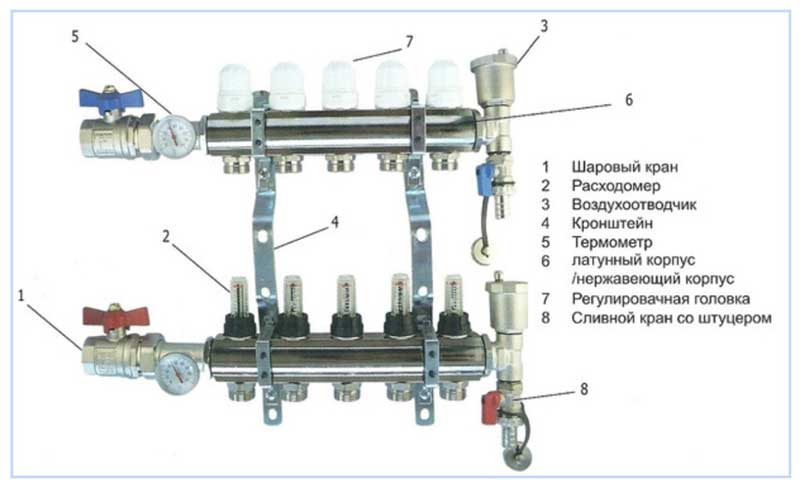
Rice. 3 Collector - structural device and main components
- Circulation electric pump - included in the package of some models, the device ensures the movement of the coolant through the pipeline of the collector system with a certain pressure. The unit is installed additionally with an electric pump that circulates through the heating circuit of the entire house.
- Temperature digital sensors - installed in separate versions, measuring devices in the supply and return lines allow you to control the temperature. This helps to optimally tune the loop for the best heat dissipation and efficiency, which is observed with a difference of 10 C.
- Thermal sensor - some collector circuits incorporate a thermostatic sensor, which, when the temperature of the coolants exceeds 55 ° C, opens the power supply circuit of the compression electric pump.
- Bypass - sometimes a jumper is installed in the collector system connecting the inlet and outlet combs, the element is designed to mix the cooled coolant into the hot water entering the collector.
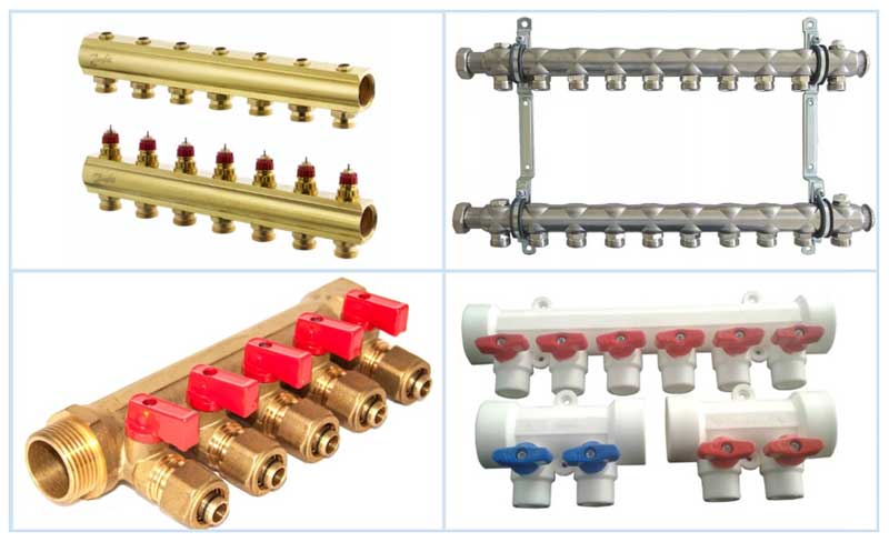
Rice. 4 Different types of combs
Functional purpose
Let's start with the fact that there is one very important rule, and if you do not strictly adhere to it, then the heating system at home will not work well. This rule states that the diameter of the outlet pipe of the heating boiler must always be equal to or slightly less than the total diameter of all circuits consuming the coolant
The best option if it is more.
For comparison, here is an example of a wall-mounted unit in which the diameter of the outlet pipe is ¾ inch. Imagine that three separate circuits will be heated due to this boiler:
- The main heating is a radiator system.
- Warm floor.
- Indirect heating boiler, which will use water intended for household needs.
Now imagine that the diameter of each circuit is at least ¾ inch, like the boiler. But the total figure will be three times higher. That is, no matter how you want, it will be simply impossible to give out the required amount of coolant through the diameter of the heating boiler nozzle so that it is enough for all three circuits.Here you have a decrease in heat transfer over the entire area of \u200b\u200bthe house.
Of course, individually, all circuits will work fine. For example, the main circuit (radiator) without the inclusion of underfloor heating will completely overpower the heated space. But as soon as you turn on the underfloor heating system, everything, neither here nor there, will not be enough coolant. The coolant has enough temperature, but its volume is not enough.
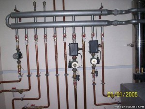
This rather serious problem is solved by installing a distribution manifold in the heating system. In fact, this is a structure made of stainless metal pipes, in the device of which devices are installed for the input and output of the coolant distributed along the circuits. To control the temperature, pressure, flow volume and speed, shut-off valves are installed along the outlets, which performs all the necessary functions.
Most importantly, with the help of a distribution manifold, you can control the temperature in a single room. And it will not affect the neighboring rooms and the temperature of the house as a whole.
Collector device
The collector consists of two pipes:
- Connects the supply pipe from the boiler to the supply circuits of heating systems. This compartment helps the distribution of hot water. His device is especially helpful when the question arises of repairing one or another branch. At the same time, on a certain circuit where it is necessary to carry out repair work, the shut-off valve closes. It simply shuts off the coolant supply.
- The return compartment regulates the pressure inside each circuit, which is how the quality of the coolant movement is achieved. And, therefore, the quality of heat transfer of heating systems.
Anyone who does not understand what the essence of the installation of a distribution manifold is, begins to build various additional installations into the heating system: a circulation pump, valves for various purposes, and so on. Let's face it, this will not help, with their help it is impossible to increase the volume of the coolant. You will simply make extra expenses that will turn out to be in vain.
Attention! If you are the owner of a large multi-storey building, it is recommended to install a separate distribution manifold for each floor
Homemade collector
It is important to follow the direction
Making a homemade distribution manifold must begin with planning. You need to determine for yourself some components of the heating network at home.
- The number of circuits where the coolant will be directed.
- Number of heating equipment. Do not forget to decide on its power, water temperature and so on. That is, you will need its technical characteristics.
- If in the future you plan to integrate additional heating elements into the heating system, for example, a heat pump or solar panels, then it is best to take them into account in advance.
- Number of additional equipment (pumps, valves, fittings, storage tanks, thermometers, pressure gauges, etc.).
Now the design of the device is being determined, it is especially necessary to take into account how each circuit will fit and from which side (bottom, top, side)
We draw your attention to some of the nuances of connection
- Gas or electric boilers are connected to the collector either from below or from above. If a circulation pump is installed in the heating system, then the connection is made only from the end of the comb.
- Boilers of indirect heating and solid fuel units crash into the collector only from the end.
- The supply circuits of heating systems cut either from above or from below.
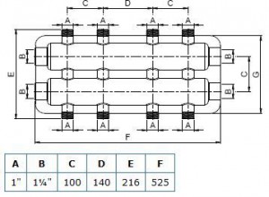
It is good if a small drawing of the collector design is transferred to paper. This will give a visual picture, according to which it will be easier to manufacture the device. In addition, it can accurately indicate the dimensional characteristics that will have to be maintained during the manufacturing process.For example, the distance between the nozzles of the supply and return circuits should be within 10-20 cm. You should not do more or less, it will simply be inconvenient in terms of maintenance. The distance between the two compartments (supply and return) should be in the same range.
Make the device compact and beautiful. We recommend that you mark all threaded connections in the figure, indicating the dimensions of the thread, do not forget to sign all the necessary contours. This will ensure that you do not make a mistake when connecting. Now it becomes clear from the sketch how much and what materials you will need to make a homemade distribution manifold.
Manufacturing process
Please note that the supply and return compartments can be made from round or square pipes. Many masters prefer the latter option
They claim that it is easier to work with him.
So, here is the production sequence:
- For all dimensions that were indicated on the sketch, it is necessary to prepare the appropriate materials. It's almost all pipes.
- They are connected according to the design of the drawing in accordance with the purpose of each.
- The connection is made using a welding machine.
- Places of welding must be cleaned with an iron brush, if necessary, degreased.
- The finished device must be tested for leaks. Therefore, all pipes will have to be closed tightly, leaving only one. Hot water is poured into it. If none of the joints dripped, then the work was carried out at a high level.
- The collector must be painted and dried.
- It is possible to carry out installation and connection of all pipe systems with the installation of stop valves.
An easier option
Now to the question, isn't it better to buy a ready-made version? There is one "BUT" here. The finished distribution manifold may not exactly fit your heating system; you will have to align the thermal performance in other ways. For example, installing an additional comb. And this is an extra cost and an extra amount of ongoing installation work. And a home-made comb, in which you took into account all the design features of the heating of your home, will definitely fit it and will work efficiently and rationally.
So it’s worth thinking about the question that was posed at the beginning of the article, how to make a distribution manifold with your own hands? Let's just say that this is a simple process that you will spend one day on. But you simply must have the skills to work with a welding machine and other plumbing tools. Without this, it will be impossible to guarantee the quality of the device.