Tichelman loop for two floors or more
Most often, such a heating system is mounted in one-story buildings of a large area. It is in such houses that it works most effectively. However, sometimes such a system is also assembled in two-three-story buildings. When performing wiring in such houses, a certain technology should be followed. According to the Tichelman scheme, in this case, not each floor is tied up separately, but the entire building as a whole. That is, an equal sum of the lengths of the return and supply pipelines for each radiator of the house is maintained.
The Tichelman loop on two floors is thus assembled according to a special scheme. Also, experts believe that it is not advisable to use only one circulation pump in this case. If possible, it is worth installing one such device on each floor in the building. Otherwise, if a single pump breaks down, the heating will be turned off in the whole house at once.
The volume of water in the system
Of course, in order for the Tichelman loop heating system to work efficiently, it is necessary to calculate, among other things, the required coolant flow rate before installing it. To determine this parameter, you should first calculate the heat loss of the building. This can be done using the formula G \u003d S * 1 / Po * (Tv - Tn)k. Here Po is the heat transfer resistance, Tv and Tn are the air temperature in the street and in the house, k is the reduction factor. The first and last indicators are determined according to the tables, depending on the design features of the building. Actually, the coolant flow itself is calculated by the formula Q \u003d G / (c * (T1-T2)), where:
- c is the specific heat capacity of water (4200),
- T1 is its return temperature,
- T2 - in the supply pipe.
The last two parameters are determined taking into account the non-linearity index of heat transfer from radiators. Ultimately, the difference between their values \u200b\u200bshould be approximately 15-20 C.
The opinion of the owners of country houses about the system
According to most owners of suburban real estate, this scheme is really very effective - the Tichelman loop. Reviews such a system deserved just excellent. In the house, with its proper design and assembly, a very comfortable microclimate is established. At the same time, the system equipment itself rarely breaks down and lasts a long time.
Not only the owners of residential buildings, but also the owners of summer cottages speak well of the Tichelman loop. The heating system in such buildings during the cold season is often used irregularly. If the wiring is done according to a dead-end scheme, when the boiler is turned on, the rooms warm up extremely unevenly. With an associated system, such problems, of course, do not arise. But the assembly of heating according to such a scheme is really more expensive than according to a dead end.
Installation features when balancing is needed
As already mentioned, the Tichelman loop does not require adjustment of the amount of coolant passing through the radiators. But only when radiators of the same capacity are installed in the building. However, in large houses, such a scheme for assembling a heating system is rarely used. For example, in the boiler room and other utility rooms, weak radiators are usually installed, and in living rooms - more powerful models. Of course, all these batteries will need different ducts. If the coolant flow is calculated for weak radiators, it will not be enough for powerful ones. With reverse circuits, hydraulic noise will begin to occur in small batteries. To prevent this from happening, balancing cranes are installed.
Installation procedure
The work consists of the following operations:
- Boiler installation. The required minimum room height for its placement is 2.5 m, the allowable volume of the room is 8 cubic meters. m.The required power of the equipment is determined by calculation (examples are given in special reference publications). Approximately for heating 10 sq. m requires a power of 1 kW.
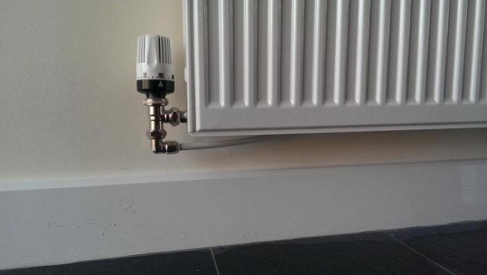
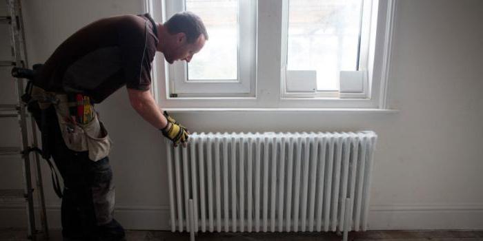
- Mounting of radiator sections. The use of biometric products in private homes is recommended. After selecting the required number of radiators, their location is marked (usually under window openings) and fastened with special brackets.
- Pulling the pipeline of the associated heating system. The use of metal-plastic pipes is optimal, which successfully withstand high temperature conditions, are distinguished by durability and ease of installation. The main pipelines (supply and “return”) from 20 to 26 mm and 16 mm for connecting radiators.
- Installation of a circulation pump. Mounted on the return pipe near the boiler. Tapping is done through a bypass with 3 taps. A special filter must be installed before the pump, which will significantly increase the life of the device.
- Installation of an expansion tank and elements ensuring the safety of the equipment. For a heating system with a passing movement of the coolant, only membrane expansion tanks are selected. Elements of the safety group are supplied with the boiler.
For tracing doorways in back rooms and utility rooms, it is allowed to mount pipes directly above the door. In this place, to prevent air accumulation, automatic air vents must be installed. In residential areas, pipes can be laid under the door in the body of the floor or bypassing the obstacle using a third pipe.
The Tichelman scheme for two-story houses provides for a certain technology. Piping is carried out with tying the entire building as a whole, and not each floor separately. It is recommended to install one circulation pump on each floor while maintaining equal lengths of return and supply pipelines for each radiator separately in accordance with the basic conditions of an associated two-pipe heating system. If you install one pump, which is quite acceptable, then if it fails, the heating system will turn off in the entire building.
Many experts consider it expedient to arrange a common riser on two floors with a separate piping on each floor. This will allow taking into account the difference in heat losses on each floor with the selection of pipe diameters and the number of required sections in radiator batteries.
A separate associated heating circuit on the floors will greatly simplify the system setup and allow for optimal balancing of the heating of the entire building. But to obtain the desired effect, it is necessary to insert a balancing crane into the trailing circuit for each of the two floors. Cranes can be placed side by side directly next to the boiler.
Mounting the Tichelmann loop useful tips
The layout of the rooms can complicate the assembly of such a system. For example, highways in any case will have to be pulled in the area of \u200b\u200bthe door. In utility rooms, pipes are allowed to be laid over the opening. Indeed, in this case, special attention is usually not paid to the design of the room. In residential premises, the pipe is most often pulled under the door. To do this, you may need to perform a procedure such as punching a screed. If, for some reason, a broach cannot be done under the door, the return pipe returns to the same place where the feed came from. In this case, sections appear in the system, where not two, but three pipes pass. This scheme is sometimes used in private homes. But the assembly of the heating system is expensive. Therefore, as mentioned above, in this case it is worth considering using a collector or dead-end circuit.
Tichelman heating feature
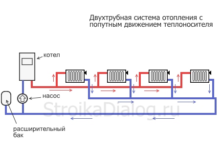
The idea of changing the principle of operation of the "return" was justified in 1901 by the German engineer Albert Tichelman, after whom it got its name - the "Tichelmann loop". The second name is “reverse type return system”. Since the movement of the coolant in both circuits, supply and return, is carried out in the same direction, a third name is often used - “scheme with the associated movement of heat carriers”.
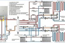
The essence of the idea is the presence of the same length of straight and reverse pipe sections connecting all radiator batteries with a boiler and a pump, which creates the same hydraulic conditions in all heating devices. Circulation circuits of equal length create conditions for the hot coolant to pass the same path to the first and last radiators with the same heat energy being received by them.
Tichelman loop diagram:
The volume of water in the system
Of course, in order for the Tichelman loop heating system to work efficiently, it is necessary to calculate, among other things, the required coolant flow rate before installing it. To determine this parameter, you should first calculate the heat loss of the building. This can be done using the formula G \u003d S * 1 / Po * (Tv - Tn)k. Here Po is the heat transfer resistance, Tv and Tn are the air temperature in the street and in the house, k is the reduction factor. The first and last indicators are determined according to the tables, depending on the design features of the building. Actually, the coolant flow itself is calculated by the formula Q \u003d G / (c * (T1-T2)), where:
- c is the specific heat capacity of water (4200),
- T1 is its return temperature,
- T2 - in the supply pipe.
The last two parameters are determined taking into account the non-linearity index of heat transfer from radiators. Ultimately, the difference between their values \u200b\u200bshould be approximately 15-20 C.
One-pipe and two-pipe system open and closed loop
In addition to the type of wiring and the location of the riser, variations in heating schemes are also divided into single-pipe and two-pipe. Single-pipe schemes are quite rare: they are used mainly in the design of large areas. In residential buildings, they are almost never found.
Single pipe heating system
In a single-pipe system, there is no supply and return pipeline, the coolant circulates through one single pipe, which is only mentally divided in half, counting the first part that delivers water from the boiler as the supply, and the remaining half of the pipe as the return. In a one-pipe system, hot water heated in the boiler rises, being forced out by a cold return flow and enters the heating devices through the wiring, flowing from one to another, cooling down and returning to the boiler for heating. Pumping circulation helps the correct flow of fluid through the circuit.
The main problem of the circuit is the loss of heat by the coolant: the water reaches the last battery barely warm.This problem is solved by installing a pump and more radiators as they move away from the boiler. It helps to save heat by installing pipes in such a way that the first radiators where the water from the heating element that has not yet cooled down are the batteries located in the coolest rooms, which require a lot of energy for heating.
Two-pipe heating system
Although single-pipe systems are cheaper, two-pipe systems are more popular. One delivers hot water from the boiler to the radiators, and the second collects the return flow of the cooled coolant and transports it back to the boiler. A two-pipe associated heating system, like a two-pipe dead-end system, is distinguished by the fact that water enters all heating radiators with the same temperature, the problem of uneven heating does not arise. A thermostat can be installed on each heating element and the heat supply can be regulated, which allows additional savings on space heating. Pipes for installation are thinner and look more neat, neater fitting into the interior.
The weaknesses of a two-pipe heating heating system include the need to install shut-off valves and a Mayevsky crane on each heating element. Dead-end and associated schemes They divide the heating circuits and according to the principle of movement of the coolant in them. An associated heating system implies the movement of water in the supply and return lines in the same direction. A dead-end heating system assumes that the water in the return line moves in the opposite direction to the supply.
The dead-end circuit is not characterized by the same length of the contour rings of the heating radiators. The farther the radiator is located from the riser, the more water travels, moving from the boiler to the radiator and back. The farther the heating element is from the heating element, the longer its contour. Associated heating circuit - a circuit where the maximum identity of the material resistance value is realized, and the length of the heating pipes forming the contour rings is the same. The voltage in the circuits is also the same, which makes the distribution of resistance throughout the heating system uniform and facilitates its balancing. The disadvantage of an associated heating system with pump circulation is a more tangible cost, because you need to buy more pipes. In conclusion, it is worth remembering all the positive aspects of the schemes with the pump, because of which they are preferred:
-
- Such a system is launched in a short time
- The circuit with the pump works without losses, providing efficient heating of the room
- Pumps are durable and work without repair for a long time
- The pump makes no noise and consumes little electricity
WATCH VIDEO
Pumped circulation heating systems are very efficient. The advantages of heating systems with a pump outweigh the disadvantages.
Traditionally used heating schemes
- Single pipe. The circulation of the heat carrier is carried out through one pipe without the use of pumps. Radiator batteries are connected in series on the main line, from the last one the cooled carrier returns to the boiler through the pipe (“return”). The system is simple to implement and economical due to the need for fewer pipes. But the parallel movement of flows leads to a gradual cooling of the water, as a result, the carrier arrives at the radiators located at the end of the series chain significantly cooled. This effect increases with an increase in the number of radiator sections. Therefore, in rooms located near the boiler, it will be excessively hot, and in remote ones it will be cold. To increase heat transfer, the number of sections in the batteries is increased, different pipe diameters are installed, additional control valves are installed, and each radiator is equipped with bypasses.
- Two-pipe.Each radiator battery is connected in parallel to the pipes for the direct supply of hot coolant and the “return”. That is, each device is equipped with an individual output to the “return”. With the simultaneous discharge of cooled water into the common circuit, the coolant returns to the boiler for heating. But at the same time, the heating of heating devices also gradually decreases as they move away from heat sources. The radiator located first in the network receives the hottest water and is the first to give the carrier to the “return”, and the radiator located at the end receives the coolant last with a lower heating temperature and also the last to give water to the return circuit. In practice, in the first device, the circulation of hot water is the best, and in the last, the worst. It is worth noting the increased price of such systems compared to single-pipe ones.
Both schemes are justified for small areas, but are inefficient for extended networks.
An improved two-pipe is the Tichelman heating scheme. When choosing a specific system, the availability of financial opportunities and the ability to provide the heating system with equipment that has the optimal required characteristics is decisive.
Installation steps
The assembly of the heating system according to this scheme is carried out in the usual manner. That is:
The boiler is installed. The height of the room where it will be installed should not be less than 2.5 m. At the same time, 8 m 3 is considered the minimum allowable room volume. The boiler is usually chosen based on the fact that it requires 1 kW of power per 10 m 2 of the room.
Radiators are mounted. The most popular type of this equipment are bimetallic batteries. Before hanging radiators, markup should be done. This heating equipment is usually mounted on special brackets.
The highways themselves are stretched. Most often, metal-plastic pipes are used to assemble heating systems, including associated ones. Their advantages include ease of installation, the ability to withstand even very high temperatures and durability.
A circulation pump is installed. This device is usually mounted in the immediate vicinity of the boiler, on the return pipe. You need to embed it through a bypass with three taps. A filter must be installed in front of the circulation pump. This addition will greatly extend its lifespan.
An expansion tank and a safety group are mounted. The first is connected to the return line through one pipe. Of course, for the Tichelman system, you need to choose a membrane expansion tank. The safety group usually comes with the boiler.
Horizontal and vertical risers
If the pipes connecting all the heating devices to each other are located in a horizontal plane, this is a heating scheme with a horizontal riser. This approach is more economical, because requires fewer pipes and requires less installation costs. A horizontal heating riser - a hot water supply line, is more common in one-story buildings with a long length, because. with such a layout, it is more reasonable to connect the radiators in series one after the other.
Heating system with horizontal piping
Such a design makes it possible to set separate temperature conditions for rooms, use heat meters. The disadvantage of the design is the occurrence of air jams in the pipes. To eliminate this problem, Mayevsky cranes are installed on the batteries in order to release the resulting excess air.
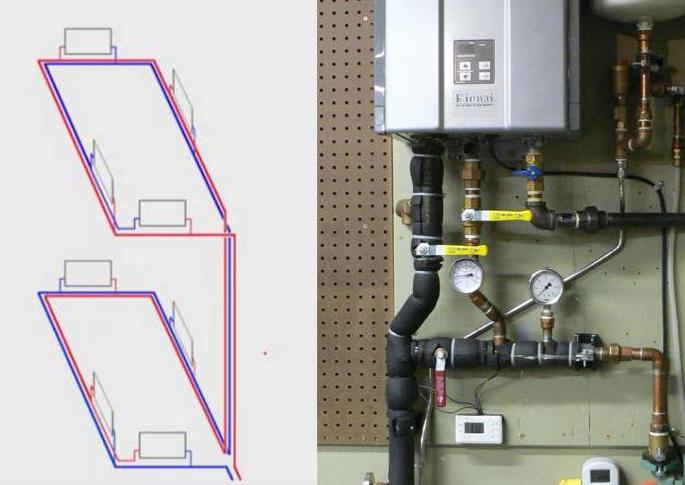
If the heating scheme with a pump involves connecting radiators located on different floors to a common line, then this is a vertical riser heating system. With this installation scheme, radiators that heat one apartment are fed from different risers, which makes it difficult to account for heat consumption in a single apartment.In a vertical heating circuit, the supply line runs under the ceiling of the upper floor or in the attic, and all heaters are connected in series to the main riser, which is located vertically and passes through all floors. Schemes of this type are used in multi-storey residential buildings. Each floor can be connected to a vertical riser separately, this will come in handy if the house is put into operation gradually. A vertical riser solves the problems of air accumulation in pipes, but the installation of such a design is more expensive.
An example of a vertical heating scheme for a private two-story house
The riser can run right through the apartment: penetrating the floor and ceiling in every room or located outside the living quarters. In the second option, it carries large heat losses, so it is “dressed” with a heat-insulating coating or placed in an insulated shaft. In a circuit with a vertical riser, it is impossible to build underfloor heating, it is difficult to maintain the required air temperature in different rooms. The upper floors are warmer than the lower ones, and the risers that are located further from the supply line are colder than those that are closer.
If heating devices are mounted directly to the distribution manifold, and each of them has a supply pipe and a return pipe, such a scheme is called a collector or beam. This approach is more expensive than the previous options, but is used in the installation, because. makes it possible to reduce the use of shaped elements and make the coolant velocity the same in all circuits.
Wiring lower and upper scheme of autonomous circulation
According to the types of wiring, heating circuits are divided into structures where the wiring is lower and upper. With the lower wiring, the supply line is laid in the lower part of the coolant flow pattern, as is the return pipe. Both lines are located below the heaters. This design has a high hydraulic stability, it is convenient in that it allows you to take out the vertical pipes of the risers outside the rooms. All circuit regulators (valves, locking mechanisms) with this arrangement are located in the same room, as a rule, this is a basement or a technical floor.
Lower type of piping of the heating system
Lower wiring of heating pipes saves heat, because. they are not laid in attic spaces or interceiling spaces. The disadvantage of this type of heating is the need to install air bleed valves for each battery, as well as constant air plugs.
With the upper type of wiring, the pipeline with the coolant passes in the upper part of the heating circuit. As a rule, it is located in the attic or in the space between the ceiling and the roof. Return pipes are mounted below the heating radiators. An expansion tank is placed at the highest point of the circuit. It regulates the pressure inside the structure and eliminates the appearance of air congestion. This type of heating cannot be installed in a house where there is no slope at the roof. The minus of the upper wiring is the negative gravitational pressure in vertical pipes. This interferes with the flow of water and reduces hydraulic stability. With the upper wiring, it is impossible to drain the risers centrally.
In addition to the lower and upper wiring, there is also a mixed one: the supply line runs from above, and the return pipeline runs at the bottom of the heating structure. This approach is reasonable if a multi-storey building has its own autonomous boiler located under the roof.
Installation procedure
The work consists of the following operations:
- Boiler installation. The required minimum room height for its placement is 2.5 m, the allowable volume of the room is 8 cubic meters. m. The required power of the equipment is determined by calculation (examples are given in special reference publications). Approximately for heating 10 square meters. m requires a power of 1 kW.
- Mounting of radiator sections.The use of biometric products in private homes is recommended. After selecting the required number of radiators, their location is marked (usually under window openings) and fastened with special brackets.
- Pulling the pipeline of the associated heating system. The use of metal-plastic pipes is optimal, which successfully withstand high temperature conditions, are distinguished by durability and ease of installation. The main pipelines (supply and “return”) from 20 to 26 mm and 16 mm for connecting radiators.
- Installation of a circulation pump. Mounted on the return pipe near the boiler. Tapping is performed through a bypass with 3 taps. A special filter must be installed before the pump, which will significantly increase the life of the device.
- Installation of an expansion tank and elements ensuring the safety of the equipment. For a heating system with a passing movement of the coolant, only membrane expansion tanks are selected. Elements of the safety group are supplied with the boiler.
For tracing doorways in back rooms and utility rooms, it is allowed to mount pipes directly above the door. In this place, to prevent air accumulation, automatic air vents must be installed. In residential areas, pipes can be laid under the door in the body of the floor or bypassing the obstacle using a third pipe.
The Tichelman scheme for two-story houses provides for a certain technology. Pipe wiring is carried out with tying the entire building as a whole, and not each floor separately. It is recommended to install one circulation pump on each floor while maintaining equal lengths of return and supply pipelines for each radiator separately in accordance with the basic conditions of an associated two-pipe heating system. If you install one pump, which is quite acceptable, then if it fails, the heating system will turn off in the entire building.
Many experts consider it expedient to arrange a common riser on two floors with a separate piping on each floor. This will allow taking into account the difference in heat losses on each floor with the selection of pipe diameters and the number of required sections in radiator batteries.
A separate associated heating circuit on the floors will greatly simplify the system setup and allow for optimal balancing of the heating of the entire building. But to obtain the desired effect, it is necessary to insert a balancing crane into the trailing circuit for each of the two floors. Cranes can be placed side by side directly near the boiler.
Tichelman heating scheme
In country houses, autonomous heating is most common. This is due to the lack of centralized or non-passage of main gas pipelines in most rural areas. For heating, small-sized boilers are used, operating on solid, liquid fuels, electric energy and natural gas supplied in cylinders. The most commonly used water heating, characterized by simplicity and reliability, compactness and hygiene. The main equipment for this method includes the following elements:
- hot water boiler;
- radiator batteries;
- water pipes;
- expansion tank;
- shut-off and control valves.
Tichelman heating feature
The idea of changing the principle of operation of the "return" was justified in 1901 by the German engineer Albert Tichelman, after whom it got its name - the "Tichelmann loop". The second name is “reverse type return system”. Since the movement of the coolant in both circuits, supply and return, is carried out in the same direction, a third name is often used - “scheme with the associated movement of heat carriers”.
The essence of the idea is the presence of the same length of straight and reverse pipe sections connecting all radiator batteries with a boiler and a pump, which creates the same hydraulic conditions in all heating devices. Circulation circuits of equal length create conditions for the hot coolant to pass the same path to the first and last radiators with the same heat energy being received by them.
Tichelman loop diagram: