Boiler control panel
Modern boilers are automated: there is a control panel on the front panel of each boiler. There are several buttons on it, including the main ones - “on” and “off”. Using the buttons, you can set the boiler operating mode - minimum, economical, enhanced. For example, in winter, the owners leave home for a long time, but so that the heating system does not freeze, they set the boiler to a minimum (it is also supporting) mode. And the boiler provides a temperature of +5 °C in the house.
The enhanced mode is used when the house needs to be heated urgently, say, to a temperature of 20 ° C. We press the corresponding button, set the temperature controllers on batteries to 20 ° C. Automation starts the boiler at full power. And when the temperature in the rooms reaches the set value, the remote thermostats installed in the room are activated and the economy mode automatically turns on, it also maintains the desired temperature. Depending on the operating mode, the automation delivers either more or less fuel. In addition, a weekly programmer can be connected to the system and the temperature can be programmed for any day.
The automatic unit has sensors that respond to malfunctions of the boiler. They turn off the system in a critical situation (for example, if the boiler body overheats or runs out of fuel, or if another malfunction occurs). But automation also has a minus: the electricity is turned off, the automation is turned off, followed by the entire heating system. But some domestic boilers work without electricity, for example, AOGV (gas-fired water heating unit), KCHM (modernized cast-iron boiler, runs on gas). If the electricity is often cut off, then this problem for an automatic heating system can be solved in two ways.
- Install AC batteries, they are capable of providing the required current for a short time (from an hour to a day).
- Put an emergency generator, it automatically turns on when there is a power outage in the network and gives current until the power is supplied.
1. Basic principles of automation of boiler houses
reliable,
economical and safe operation of the boiler room
with a minimum number of attendants
personnel can only be carried out
with thermal control
automatic control and
process control,
alarm and equipment protection
.
Main
boiler room automation solutions
accepted during the development of schemes
automation (functional diagrams).
Automation schemes are being developed
following the design of heat engineering
schemes and decision-making on the choice
main and auxiliary equipment
boiler room, its mechanization and
thermal communications. TO
the main equipment is
boiler, smoke exhausters and fans,
and to the auxiliary pumping and deaerator
installation, chemical water treatment, heating
installation, condensate pumping station,
GDS, fuel oil (coal) storage and fuel supply.
Volume
automation is accepted according
with SNiP II-35-76 (section 15 - "Automation")
and manufacturers' requirements
thermal mechanical equipment.
Level of automation
boiler rooms depends on the following main
technical factors:
—
boiler type (steam, hot water,
combined - steam water heating);
—
boiler design and equipment
(drum, straight-through, cast iron
sectional supercharged, etc.), type of thrust
etc.; type of fuel (solid, liquid,
gaseous, combined
gas-oil, pulverized) and type
fuel-burning device (TSU);
—
nature of thermal loads
(industrial, heating,
individual, etc.);
— number of boilers in
boiler room.
At
drawing up an automation scheme
provide the main subsystems
automatic control,
technological protection, remote
management, thermal control,
technological blocking and signaling.
Reducing the cost of paying for thermal energy
ITP automation is one of the most effective tools
for
reducing the cost of paying for thermal energy.
4.1. Automation ITP provides
water temperature regulation,
coming to
heating system, depending on the outside temperature. This
allows you to reduce the "overflow" of the building in
autumn-spring period and reduce the
the most "useless" costs of thermal energy.
4.2. An additional reserve for saving thermal energy is
adjustment
temperature of the coolant supplied to the heating system according to
temperature
return water, taking into account the real mode of operation of the heat supply
organizations.
4.3. Maintaining the temperature of the water in the return pipeline in
According to
temperature of the heat carrier in the supply pipeline of the heating network (see.
3.3)
allows you to avoid claims and penalties of the heat supply
organizations.
For example, CHPP-5 in case of systematic excess of the average daily
temperature
"returns" by more than
3°C charges an additional fee for
"Unused thermal energy". This value
is determined by the formula:
∆Wunderestimated=
M2∙(T2F-T2GR)/1000
∆Wunderestimated–
The value of "underutilized heat
energy” for the billing monthly period, Gcal.
M2
- the amount of coolant for the heating system;
ventilation for
settlement monthly period, T;
T2F
– actual return water temperature, °C;
T2GR–
return water temperature
corresponding to the temperature in the supply pipeline of network water,
°C;
1000
-coefficient for conversion to Gcal.
Practice shows that
the value of ∆W is underestimated. reaches 50% of
total
heat consumption for 1 month.
4.4.
Modern controllers allow
use the setpoint (correction) to the desired water temperature,
coming to
heating system. This setting allows you to automatically lower
temperature in
production facilities at night and on weekends,
then
exceed it during business hours. Residential buildings use automatic
decline
temperature at night.
Thus, the automation of heat consumption provides a significant
savings in thermal energy, which reaches 50%.
Correction of the temperature of the water supplied to the heating system according to the temperature of the return coolant
3.1.
Purpose of adjustment
temperature in the heating supply pipe by temperature
returned
coolant.
3.2. Classical technique
adjustments
heating temperature "return" and its lack.
To keep up with the schedule
return temperature
ITP automation
starts to work on a different algorithm. Now the controller calculates
v
depending on the outdoor temperature, the desired temperature is not
only
for the heating supply pipeline, but also for the return pipeline.
When
exceeding the temperature of the returned coolant of the calculated value
–
the reference for the flow line is reduced by the corresponding
size. This
the function is present on many temperature controllers, both domestic and
and
imported production.
The task of adjusting the temperatures supplied to the heating system
coolant with
to maintain the required return water temperature, many
controllers such as ECL. However, this method of regulation
leads to
errors for a simple reason: the heat supply organization does not support
declared temperature chart. In the heating networks of St. Petersburg,
which
should function according to the schedule 150/70 ° C, the water temperature in
server
pipeline, as a rule, does not exceed 95°C.
Heat supply organizations require that the temperature of the return
coolant corresponded to the temperature of the water in the supply pipeline.
Consider an example:
— outside -20°C, according to the heating schedule 150/70
supply pipeline
the heating system should have a temperature of 133.3 °C. However, in fact
the heating network issues
temperature in the supply pipe is 90.7°C, which corresponds to
temperature
outside air -5°С. Based on outdoor temperature
-20°C the controller calculates the required temperature
return coolant
64.6°C (see Fig. 1 - graph 150/70 C).
but
the heat supply organization requires the consumer to return
coolant is not
warmer than 49°C, which corresponds to the temperature of the water coming from
heating networks. If
return temperature exceeds 49°C, controller
will not be
adjust the heating temperature setpoint until the temperature in
reverse
pipeline will not exceed 64.6°C, which means that the task
maintaining
required return water temperature has not been resolved and the heat supply
organization
has the right to present a claim to the subscriber regarding the overestimation of temperature
reverse
water (see item 4).
3.3.
New Decision.
Automation
ITP is based on
freely programmable controller MS-8 or MS-12. On the pitcher
pipeline
heating networks install an additional temperature sensor. To the algorithm
work
controller, in addition to the standard two heating curves for
server and
return heating pipelines relative to the outdoor temperature
air
(provided by many modern controllers) include two
additional graphics for supply and return pipelines
heating
relative to the temperature in the heating supply pipe. V
developed
algorithm compares two set temperature values
returned
coolant: relative to the outdoor temperature and
relatively
temperature in the supply pipeline of the heating network. Graph correction in
server
the pipeline is conducted relative to the smallest of these two values.
So
Thus, the consumer of thermal energy avoids fines for exceeding
temperature of the returned coolant at reduced parameters
thermal
networks.
An additional advantage of the above algorithm is
promotion
system survivability. For example, if a sensor fails
temperature
outdoor air, with standard algorithms, ITP automation does not
working.
The developed new algorithm for this accident provides
functioning
automatic regulation regarding the temperature in the supply
pipeline
heating networks.
ITP automationmodern technical solutions
Automation
ITP makes it possible to maintain the required parameters of heat supply,
reduce
consumption of thermal energy due to weather compensation, to produce
diagnostics of the operation of equipment and the system as a whole, upon detection
contingency
situation, issue an emergency signal and take measures to reduce damage from
given
emergency situation.
ITP automation is being designed
taking into account the complexity of the object, wishes
Customer. The choice of equipment and circuit solutions also depends on
whether heat supply dispatching (or ITP dispatching) is required.
The control system can
be built as on hard-coded
microprocessor temperature controllers (ECL -
"Danfoss", TPM - "Aries", VTR
–
Vosges, etc.), and on the basis of
freely programmable controllers. Holding
commissioning of the latter requires high qualification
adjusters. Tem
However, in recent years, most of our projects are carried out on
base
namely freely programmable controllers. Their use
conditioned
the following reasons:
a) Applicability
non-standard algorithms that take into account
technical
features of a particular object and changing requirements
heat supply
organizations.
b) Possibility of minimization
consequences
emergency situation.
c) Reduced hardware
redundancy:
taken from any
sensor information can be used for various purposes;
for example, with
one pressure sensor information can be obtained and formed
commands
according to the following situations: emergency high pressure, replenishment of the secondary
contour
heat exchanger, the threat of airing the system, dry running of the pump,
current
pressure value for dispatching.
d) Possibility of use
information
from some types
calculators (heat, gas, electricity); for example, you can not
duplicate
sensors of the thermal energy metering unit, and receive data from these sensors
across
SPnet.
e) Applicability
peripheral devices with any
standard and
even with non-standard characteristics, easy replacement of devices (sensors,
drives, etc.) with some characteristics to devices with other
characteristics, which may be important for the prompt replacement of outdated
from
building elements or when upgrading.
f)
Ease of changing the algorithm
control (without rewiring
or with minor alterations of the scheme).
g) One device
(controller) manages all equipment
thermal
point, which greatly simplifies the electrical circuit diagram
closet
management, this is especially important if automation and dispatching
are solved
at a high enough level. The use of additional
elements
automation, such as intermediate relays, timers, comparators, etc.
So
Thus, the electrical circuit of the control cabinet is simplified, which reduces
expenses,
this is all the more important if complex automation is being designed, for example,
automation of ITP of high-rise buildings
h)
The controller produces detailed
diagnostics practically
all equipment and modes of operation.
i)
The multivariance of bringing diagnostic messages to
maintenance personnel (signal lamps, detailed information on
remote control
controller, local dispatching of heat supply through local
net
Ethernet, remote dispatching of heat supply and other processes
across
Internet, sending SMS messages to the responsible person).
j)
The multivariance of bringing diagnostic
messages before
maintenance personnel (signal lamps, detailed information on
remote control
controller, local dispatch via Ethernet,
remote
dispatching via the Internet, sending SMS messages to the person in charge
face).
k) Low price for
quality domestic
freely programmable
KONTAR controllers manufactured by OAO Moscow Plant
thermal automation",
which has become comparable to the price of hard-coded
controllers
(weather compensators).
Thermal control
Organization
thermal control and instrument selection
carried out in accordance with
the following principles:
- parameters,
monitoring is necessary for
operation of the boiler house are controlled
indicating instruments;
- parameters,
changes that could lead to
emergency condition of the equipment,
controlled by signaling
indicating instruments;
- parameters,
accounting for which is necessary for the analysis
operation of equipment or household
settlements are controlled by registering
or summing devices.
For
steam boilers control requirements
thermal parameters are determined
operating steam pressure and design
steam capacity. For instance,
steam oil-fired boilers DE-25-14GM
(Fig. 4.1 and 4.2) are equipped with indicating
instruments for measuring:
– temperature
feed water before and after the economizer
technical thermometers type 1 P
or At;
– temperature
steam behind the superheater to the main
steam valve with technical thermometer
3 types P or
At;
– temperature
flue gas millivoltmeter E4
type W4540/1;
– temperature
fuel oil thermometer 2 types P
or At;
– pressure
steam in the drum showing pressure gauge
25 types MP4-U
and showing self-recording secondary
instrument type 20 KSU1-003;
– pressure
steam at oil nozzles with a manometer 15
type MP-4U;
– pressure
feed water at the economizer inlet
after the regulating body with pressure gauges
25 types MP-4At;
air pressure after blowing
fan pressure gauge membrane
type NML-52
and differential pressure gauge
liquid type 26 tj16300;
– pressure
fuel oil to the boiler with pressure gauges of type 16 MP-4U
and showing secondary device
13 types KSU1-003;
– pressure
gas to the boiler with membrane pressure gauges
indicating type NML-100
and showing self-recording secondary
device type 12 KSU1-003;
– pressure
gas to the igniter with a type 34 manometer
MP-4U;
- rarefaction
in the boiler furnace with a membrane draft
showing 14 types TNMP-52;
- rarefaction
in front of the smoke exhauster
differential liquid 18 type
tj24000;
– consumption
steam differential pressure gauge 33 type DSS-711Ying—M1;
– consumption
gas differential pressure gauge 31 type DSS-711Ying—M1;
– consumption
fuel oil meter fuel oil 32 type CMO-200;
– content
SO2
in flue gases with a portable gas analyzer
30 types KGA-1-1;
– level
water in the drum with a gauge glass 28 and
indicating self-recording secondary
device type 29 KSU1-003.
Level
water in the boiler drum, vacuum in
furnace, gas pressure to the boiler, pressure
fuel oil to the boiler and air pressure after
blower fan controlled
signaling devices - differential pressure gauge
E35
type Chipboard-4WITHG—M1,
pressure and draft sensor-relay E22
type DNT-1,
pressure sensor-relay E19
type DN-40,
electrocontact manometer indicating
E23
type EKM-IV,
pressure sensor-relay E21
type DN-40
and warning lights HLW
— HL7.
Thermal automation definition, device, application
 Thermal automation is a set of devices that provide thermal consumption of buildings and structures with the highest energy efficiency. The automation system includes the following devices:
- controllers and sensors for temperature readings of the thermal carrier;
- air mass temperature control sensors;
- mechanisms of executive significance (electric valves, temperature regulators, pressure regulating devices), as well as pumping equipment.
The purpose of thermal automation.
The main task of thermal automation systems for buildings is the maximum reduction of heat losses from the consumed electrical energy. The main functions of such systems:
- Control and management of the temperature of the thermal carrier depending on external (outdoor) temperature indicators.
- If necessary, lowers or raises the temperature in the building when the equipment is operating according to the schedule entered into the program. The temperature is often lowered at night, while a decrease of only 1 degree gives about 5% savings from the entire heating season.
- Temperature control in the return pipelines, if necessary, heat energy is forcibly utilized.
- It monitors the temperature regime of DHW supply to the building, if necessary, regulates it with the help of quick-response mixing valves, as well as using storage boilers.
- Effectively controls the operation of heat pumps, taking into account inertial indicators, depending on the temperature regimes in the street and in the room. Automatically activates the main and backup heating systems of buildings to prevent the occurrence of corrosion traces and sticking of bearings in pumps.
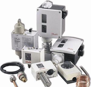
In Russia, products manufactured by Danfoss have proven themselves well in operation.
Leader in the manufacture of thermal automation
In 1993, the Russian branch of the Danish company Danfoss was founded, with the participation of the Danish investment fund. Since this period of time, radiator temperature controllers have been produced in Russia for the first time. The DANFOSS concern is a leader in the manufacture of automation systems for various engineering systems (ventilation and air conditioning, heat supply). Today, the workshops of this company offer:
- temperature regulators for heating appliances, automatic shut-off valves;
- for water supply systems (hot and cold) balancing valves;
- automation of ventilation processes in heat points;
- control devices for temperature and pressure;
- electrical devices for controlling the thermal regime in a country house, cottage;
- floor heating automation, regulation and control devices;
- components for automation of thermal processes in burners.
Quality control of manufactured products in the company at a high level at all plants
Danfoss pays special attention to the accuracy and reliable operation of all products of the plant, they all undergo strict control and testing before shipment to the consumer.
Heat supply dispatching
5.1. Purpose of dispatching
In other words,
ITP dispatching ensures the issuance of an emergency signal by sound, as well as
corresponding inscriptions and images on the computer monitor.
Automation
ITP may be associated with
computer dispatcher - operator in various ways:
across
local computer network, if the operator and ITP automation are nearby
remote from each other (located in the same or in neighboring buildings).
Organization
such a connection is cheap, practically does not require funds for its maintenance,
her
work does not depend on telecom operators. Ideal for
organizations
round-the-clock operation of the dispatch center at the facility;
— automation,
dispatching can be done via network communication
Internet, in this case, control over the system and interference in it
job can
carried out from almost anywhere in the world. For this
necessary
only provide the ability to connect to the Internet as in the place
location
controlled object, and at the location of the operator.
special
in this case, the operator does not need software
(enough
any browser to access the Internet). Now in charge
maybe
be aware of the affairs at your facility, being at any distance from it,
it is enough to have access to the Internet. This system is perfect
for
maintenance of remote objects;
- modem
communication allows you to periodically communicate with the object by
GSM or telephone channels, for example, you can organize the distribution
corresponding SMS messages when
certain situations;
- can
use a combination of several types of communication: for example, access to
Internet is easy to organize through a GPRS modem.
important
three
the last type of communication is to provide protection from unauthorized
intervention
into the operation of the system.
5.2.
Networking capabilities of controllers
Automation, dispatching
implemented with one or
several
controllers.
The controllers that work together communicate with each other via
RS485 interface.
In this case, each of the interconnected controllers can work
offline.
If the network fails, the controllers simply will not be able to exchange information
between
yourself. If the algorithm is constructed in such a way that each controller performs
autonomous
part of the algorithm, then over the network the controllers will exchange only
auxiliary
information, therefore, in the event of a network failure, significant damage to
performance
system will not happen.
To individual controllers or to groups of controllers linked to each other
friend by
RS485, the following metering devices can be connected: NPF devices
"Logics",
supporting SP NETWORK (SPG761, SPT961), electric meter SET-4TM,
heat meter
SA94, heat meter TEM106, heat meter VIS.T, heat meter VKT-7,
Electric meters Mercury 320.
Controllers (or groups of controllers) that perform independent
friend
tasks can communicate with the local dispatcher via an Ethernet link, or
With
remote - via the Internet using a server, on
which provide
special measures to protect information.
It is possible to send SMS messages about emergency situations that have occurred
responsible person.
If necessary, it is possible to connect devices operating on
protocols:
•
MODBUS RTU;
• BACnet;
• LonWork (via gateway);
• other.
Automation of thermal power plants
The modern development of the Russian energy sector is impossible without the modernization and reconstruction of outdated equipment of power plants, the introduction of modern methods for the production of electrical and thermal energy, the use of modern integrated means of automating technological processes.
ABB Power and Automation Systems has extensive experience in implementing control systems for process automation in thermal power plants.
In this case, the following main tasks are solved:
| Tasks |
Solutions |
|
Reliable protection of technological equipment |
|
|
Accident analysis |
• Automatic logging of emergency events, event logs and logs of actions of operational personnel |
|
Error-free work of operational personnel |
|
|
Improving the efficiency of operational and maintenance personnel |
|
|
Economical use of energy carriers, saving electrical energy, reducing harmful emissions |
|
|
Savings and accounting for the generation of electrical and thermal energy |
|