Classification
Heat supply systems are divided into:
- Centralized
-
Local
(they are also called decentralized).
They can be water
and steam.
The latter are rarely used today.
Local heating systems
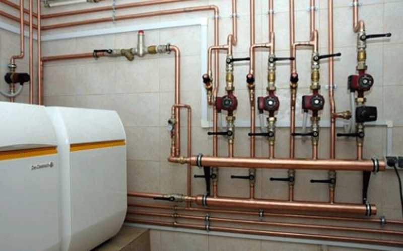
Everything is simple here. In local systems, the source of heat energy and its consumer are located in the same building or very close to each other. For example, a boiler is installed in a separate house. The water heated in this boiler is subsequently used to meet the needs of the house in heating and hot water.
District heating systems
In a centralized heat supply system, the source of heat is either a boiler house that generates heat for a group of consumers: a quarter, a city district, or even an entire city.
With such a system, heat is transported to consumers through the main heating networks. From the main networks, the coolant is supplied to central heating points (CHP) or individual heating points (ITP). From the central heating station, heat is already supplied through quarterly networks to the buildings and structures of consumers.
According to the method of connecting the heating system, heat supply systems are divided into:
Dependent systems
- the heat carrier from the source of thermal energy (CHP, boiler house) goes directly to the consumer. With such a system, the scheme does not provide for the presence of central or individual heating points. In simple terms, water from heating networks flows directly into the batteries.
Independent systems -
in this system there are TsTP and ITP. The coolant circulating through the heating networks heats the water in the heat exchanger (1st circuit - red and green lines). The water heated in the heat exchanger circulates already in the heating system of consumers (circuit 2 - orange and blue lines).

According to the method of connecting the hot water supply system, heat supply systems are divided into:
Closed.
With such a system, water from the water supply system is heated by a coolant and supplied to the consumer. I wrote about her in an article.


Open.
In an open heating system, water for DHW needs is taken directly from the heating network. For example, in winter you use heating and hot water "from one pipe". For such a system, the figure of the dependent heat supply system is valid.
Steam heating systems

Fig.4.
Schematic diagrams of steam systems
heat supply
a - one-pipe
no condensate return; b-two-pipe
with condensate return; in-three-pipe
with condensate return; 1-source
heat; 2 – steam pipeline; 3 subscriber
input; 4–ventilation heater;
5 - local system heat exchanger
heating; 6 - local heat exchanger
hot water systems;
7-technological apparatus;
8-condensate trap; 9-drainage; 10-tank
condensate collection; 11-condensate pump;
12 - check valve; 13-condensate line
How
and water, steam heating systems,
are single-pipe, two-pipe and
multipipe (Fig. 4)
V
single-pipe steam system (Fig. 4, a)
steam condensate is not returned from
heat consumers to the source, and
used for hot water
and technological needs or thrown away
into the drain. Such systems are not very economical.
and applied at low cost.
pair.
Two-pipe
steam systems with condensate return
to the heat source (Fig. 4,b) have the greatest
dissemination in practice. Condensate
from individual local heating systems
is collected in a common tank located
at the substation and then by the pump
is pumped to the heat source.
Steam condensate is a valuable product:
it does not contain hardness salts and
dissolved corrosive gases and
allows you to save up to 15% of the content
in a couple of heat.Making new batches
feed water for steam boilers
usually requires a significant investment
exceeding the cost of condensate return.
Question about return
condensate to the heat source is solved
on a case-by-case basis
technical and economic calculations.
Multipipe
steam systems (Fig. 4, c) are used
at industrial sites upon receipt
steam CHP and in case the technology
production requires a couple of different
pressure. Construction costs for individual
steam pipelines for steam of different pressures
are less than the cost
overconsumption of fuel at CHPP during the holiday
a pair of only one, the highest
pressure and subsequent reduction
its from subscribers in need of a pair
lower pressure. Condensate return
in three-pipe systems
one common condensate line. V
in some cases double steam lines
laid at the same pressure
steam in them in order to reliable and uninterrupted
supply of steam to consumers. Number
there may be more than two steam pipelines,
for example, when reserving an infeed with
CHP steam at different pressures or at
the feasibility of supplying steam from the CHP three
different pressures.
On the
large industrial hubs, uniting
several enterprises are being built
integrated water and steam systems
with steam supply for technology and water for
heating and ventilation needs.
On the
subscriber inputs of systems except
transmission devices
heat to local heat consumption systems,
the system is also important
collect condensate and return it to
heat source.
Incoming
steam usually gets to the subscriber input
into the distribution manifold, from where
directly or through reduction
valve (automatic pressure "after itself")
goes to heat-using
devices.
Types of steam heating systems
According to the method of the device, two types of steam heating are distinguished: with a closed and open system. In a closed system, condensate flows into a special receiving pipe, which is connected to the corresponding inlet of the cat. It is laid with a slight slope, so that the condensate flows through the system by gravity.

Schemes of open and closed steam heating systems
In an open system, condensate is collected in a special container. When it is filled, it is fed into the boiler using a pump. In addition to the different construction of the system, different steam boilers are also used - not all of them can work in closed systems.
In general, there are steam heating systems with pressure close to atmospheric or even lower. Such systems are called vacuum-vapor systems. What is so attractive about this setup? The fact that at low pressure the boiling point of water decreases and the system has a more acceptable temperature. But the difficulty in ensuring tightness - air is constantly sucked through the connections - has led to the fact that these schemes are practically never found.
Steam heating with low pressure is more common. Available steam boilers for domestic purposes can create a pressure not exceeding 6 atm (at a pressure of more than 7 atm, the use of equipment requires permission).
Wiring types
By type of wiring, steam heating happens:
-
With upper wiring (the steam pipeline is located under the ceiling, pipes go down from it to the radiators, a condensate pipeline is laid below). Such a scheme is most easily implemented, since hot steam moves through one pipes, cooled condensate through others, the system is stable.
- With bottom wiring. The steam pipe is located at floor level. This scheme is not the best choice, since hot steam moves up through one pipe, condensate moves down, which often leads to water hammer and depressurization of the system.
- With intermediate wiring. The steam pipeline is laid just above the radiators - approximately at the level of the window sills.The system has all the advantages of overhead wiring, except that hot pipes are within reach and there is a high risk of burns.
When laying, the steam pipeline is made with a slight slope (1-2%) in the direction of steam movement, and the condensate pipeline - in the direction of condensate movement.
Boiler selection
Steam boilers can operate on all types of fuel - gas, liquid and solid fuels. In addition to the choice of fuel, it is necessary to correctly select the power of the steam boiler. It is determined depending on the area that will need to be heated:
- up to 200 m2 - 25 kW;
- from 200 m2 to 300 m2 - 30 kW;
- from 300 m2 to 600 m2 - 35-60 kW.
In general, the calculation method is standard - 1 kW of power is taken per 10 square meters. This rule is true for houses with a ceiling height of 2.5-2.7 m. The choice of a specific model follows. When buying, pay attention to the presence of a quality certificate - the equipment is dangerous and must be tested.
Which pipes to use
Temperatures during steam heating can normally only be tolerated by metals. The cheapest option is steel. But to connect them, welding is required. It is also possible to use threaded connections. This option is budgetary, but short-lived: steel quickly corrodes in a humid environment.
Copper pipes don't corrode.
Galvanized and stainless pipes are more durable, but their price is not at all modest. But the connection is threaded. Another option is copper pipes. They can only be soldered, they are expensive, but they do not rust. Due to their higher thermal conductivity, they transfer heat even more efficiently. So such a heating system will be super efficient, but also very hot.
Advantages and disadvantages
Steam heating is not the most popular, but it has both positive and negative points. And the advantages are quite significant:
- High heating efficiency. The fact is that the steam in the system does not just heat radiators and pipes to a certain temperature. Due to the large temperature difference, it condenses. And during condensation, 1 liter of steam gives off 2300 kJ of heat. Whereas when the same amount of water cools down by 50°C, only 100 kJ is released. Therefore, a very small number of radiators are required to heat the room. In some cases, a certain number of pipes is sufficient.
-
Since steam heating is a small system, it has a low inertia. The room begins to heat up literally a few minutes after the boiler is started.
The disadvantages of steam heating systems are even more impressive:
- High steam temperature leads to heating of all elements of the system up to 100°C and above. This leads to the following consequences:
- very active air circulation in the room, which is uncomfortable, and sometimes harmful (if you are allergic to dust);
- the air in the room dries up;
- hot elements of the system are traumatic and must be closed, and pipes too;
- not all building materials normally tolerate prolonged heating to such temperatures, therefore the choice of finishing materials is very limited (in fact, it is only cement plaster with subsequent painting with heat-resistant paints).
- Simple steam heating has very limited possibilities for adjusting heat transfer. There is only one way to change the temperature - to make several parallel branches and turn them on as needed. The second way is to turn off the boiler when it overheats and turn it on after the room has cooled down. This process is controlled by automation, but this method is far from the most comfortable, as there are constant temperature fluctuations.
- The system is noisy. It makes a lot of noise when moving. In production workshops, this does not really interfere, but in a private house it can be a problem.
As you can see, steam heating is not the best choice, although it is quite inexpensive to set up.
Big Encyclopedia of Oil and Gas
The four-pipe system has two independent circuits: cool water moves one at a time, hot water the other way.The ejection closer with a four-pipe system has two heat exchangers. Cool water is supplied to the double-row heat exchanger, and hot water is supplied to the single-row heat exchanger. Three-pipe and four-pipe systems provide the ability to supply hot or cold water to any ejection closer, depending on the need. But when compared with a three-pipe system, there are no losses from mixing the heat and coolant in a four-pipe system. Moreover, the four-pipe system has a much more stable hydraulic regime.
On fig. 1.7 shows a diagram of a four-pipe heating network from a quarterly steam heat generating installation.
Water 2- and four-pipe systems are used for heating public and residential buildings. Two-pipe systems can be both closed and open, mainly with local thermal substations. Four-pipe systems are mostly closed, and up to the central thermal substation, the heating networks are made with two pipes, after the central heating station to the buildings - with four pipes. The operating mode of two-pipe heat mains is set from the condition of equipping all consumers with thermal power. In four-pipe networks, heating systems are connected to two mains (supply and return), and hot water supply systems are connected to two (supply and circulation).
In a four-pipe water-air conditioning system, the amount of primary air is set in accordance with the requirements of sanitation standards, due to which, during the warm season, the cold introduced by it is not enough to maintain the required indoor air. Therefore, in addition to the contour of the pipelines of the heat carrier, another circuit of the coolant lies. On fig. IV.77 presents an important diagram of a four-pipe system. The operation of the hot water circuit of this design is similar to the operation of the circuit of the two-pipe type system. The cold water circuit has its own circulation pump /, which pumps water first of all into the water cooler 4, then into the heat exchangers of the ejection closers.
The connection of a two-pipe type heat supply system for the needs of heat supply and ventilation with a single-pipe DHW system (open DHW circuit) leads to a three-pipe heating system. The three-pipe hydraulic system is also used in the heat supply of industrial enterprises (factory districts) with an innovative heat load of very high potential and a closed DHW circuit. In this case, to reduce initial capital investments and reduce the cost of operation, 2 lines are used as supply lines, and the third is a common return line, i.e. instead of a four-pipe system, we get a three-pipe system. Consumers of the same type in terms of potential and heat consumption mode should be connected to each supply line.
The four-pipe system has two independent circuits: cool water moves one at a time, hot water the other way. The ejection closer with a four-pipe system has two heat exchangers. Cool water is supplied to the double-row heat exchanger, and hot water is supplied to the single-row heat exchanger. Three-pipe and four-pipe systems provide the ability to supply hot or cold water to any ejection closer, depending on the need. But when compared with a three-pipe system, there are no losses from mixing the heat and coolant in a four-pipe system. Moreover, the four-pipe system has a much more stable hydraulic regime.
The four-pipe system has two independent circuits: cool water moves one at a time, hot water the other way. The ejection closer with a four-pipe system has two heat exchangers. Cool water is supplied to the double-row heat exchanger, and hot water is supplied to the single-row heat exchanger. Three-pipe and four-pipe systems provide the ability to supply hot or cold water to any ejection closer, depending on the need.But when compared with a three-pipe system, there are no losses from mixing the heat and coolant in a four-pipe system. Moreover, the four-pipe system has a much more stable hydraulic regime.
Modern heating system - schematic diagram
Heating ‘target=”_blank”>’)
-
Here
Reliable and modern beds. Cost on site. Order with delivery
dekonte.ru -
cab mans
Japanese cabins available and under the order. Profitable
lideravto.ru
About the heating system of a multi-storey building
Home heating system. as a rule, it is single-pipe; the spill is either upper or lower. As for the return and supply, they can be placed in the basement, but it is possible that the return is in the basement, and the supply is located in the attic. The movement of water in the risers can be passing and go from top to bottom or oncoming and go from bottom to top (in this regard, what matters is which house heating scheme was used).
Heating system.
There are such risers that are used with a counter coolant, they can also be associated. If the house heating scheme is exactly like this, then in any system there is a heated towel rail riser (in this case, the system can be either with an open water intake or with a closed one).
The number of sections and the size of heating radiators is very important. Such parameters must be determined through calculations as the water in the coolant cools down.
In this regard, there is one good piece of advice: if there is a desire to replace radiators with newer and more modern ones, then you should not use the services of friends, since you need to take into account the advancement and cooling of the coolant. In this case, it is recommended to use the services of a house maintenance company, and you should not throw out the jumpers, as the company is interested in restoring them
Thus, it becomes clear that a multi-storey building is heated according to a fairly simple, but very effective system. Nevertheless, if some failures have occurred, then you should not repair it yourself (especially if there is no appropriate training). In any case, it is imperative to call the masters from the service company, who, as a rule, fix all problems in the shortest possible time. Masters use the following tools:
- pipe (gas) wrench;
- wrench;
- pipe bender;
- crimping pliers.
 The comfort of residents in an apartment building depends on the correct planning and choice of the heating system. The difficulty of heating in a multi-storey building is to heat each apartment in the house almost equally with a minimum difference in temperature. To understand how the heating systems of multi-storey buildings work, let's look at the example of a standard nine-story building with a central heating system.
With the help of valves, such a house is connected to the central heating system.
Immediately after the valves, coarse filters, the so-called mud collectors, are installed. They capture large and medium fractions of dirt from the supplied hot water for home heating. After the mud collectors, another valve is installed through which hot water is supplied for the needs of the residents of the house. It turns out that in an open heating system, water is heated for two purposes at once - for heating and supplying hot water (DHW hot water supply systems). However, in order for the tenant of the house to be able to safely use hot water, the valves are installed from the supply and return of the heating system of a multi-storey building.
Under normal conditions, the temperature of hot water supply to the heating system reaches 150 degrees. To make it possible to use hot water, it is served to residents after it has passed through the heating devices of all apartments and given off heat. Hot water returned through the heating return will be no more than 60-70 degrees.If the temperature of the hot water supplied to the heating system is low (this happens at the beginning of the heating season and with slight frosts), water is taken from the supply.
After the hot water supply, another valve is installed with the help of which it is possible to shut off the heating of the house, and in some cases a collector is installed.
In houses more than five floors, a single-pipe heating system of a multi-storey building is installed.
Only the supply of hot water to the heating system can differ. Serving can be top (served from the attic) or bottom spill (served from the basement).
Since the pressure of hot water in heating systems is quite high, it is possible to achieve almost the same level of heating for each apartment in the house. The disadvantage of such a heating system is that, if necessary, drain and fill the water in the system, air may remain in the heating system. Mayevsky's crane on radiators can help solve this problem. An alternative option for central heating can be individual heating of the apartment.
CLAIM
1. A single-pipe heat supply system with heat carrier flow control, containing a set of heat exchangers (6) connected in series, so that the return pipeline of one heat exchanger (6) is the supply pipeline of the next heat exchanger (6); main supply pipeline (1) connected to the supply pipeline (3) of the first, if viewed in the direction of flow, from the heat exchangers (6); main return pipeline (2), connected to the return pipeline (4) of the latter, if viewed in the direction of flow , from heat exchangers (6); in which a heat carrier with a supply temperature is supplied at a certain flow rate from the main supply pipeline (1) to a set of heat exchangers (6); moreover, this system additionally contains a flow controller (9) connected to the return pipeline (4) , where the flow controller (9) is designed to control the flow in the return pipeline (4); the actuator (10) that controls the flow regulator (9); the temperature sensor (11), which is in a state of heat exchange with the coolant in the return pipeline (4).
2. Single-pipe heating system according to claim 1, in which the flow controller (9) is additionally designed to maintain a constant flow despite changes in pressure in the main supply pipeline (1).
3. One-pipe heat supply system according to claim 1 or 2, in which an outside temperature sensor (8) is installed to measure the outside temperature in relation to the system.
4. One-pipe heat supply system according to claim 3, in which there is an electronic regulator (18) connected to each actuator (10), and temperature sensors (11) are connected to the return pipelines (4) of the system.
5. One-pipe heat supply system according to claim 4, in which the electronic regulator (18) is connected to a temperature sensor (19) connected to the main supply pipeline (1).
6. One-pipe heating system according to claim 4 or 5, in which the electronic controller (18) is connected to the outdoor temperature sensor (8).
7. One-pipe heating system according to any one of claims 4 or 5, in which each actuator (10) is driven by pulses.
8. One-pipe heat supply system according to claim 7, in which each actuating device (10) is an electromagnetic, pneumatic, hydraulic or electrostrictive actuating device.
9. One-pipe heating system according to any one of claims 4, 5 or 8, in which the electronic controller (18) is configured to monitor the measured parameters and use these data to optimize the supply temperature setpoint depending on the outside temperature and the return temperature setpoint in depending on the flow temperature setpoint.
10.The one-pipe heat supply system according to any one of claims 1 or 2, in which each actuating device (10) is connected directly to the temperature sensor (11), is an autonomous device and contains means for adjusting the temperature set point in the return pipeline.
11. One-pipe heating system according to claim 10, in which the actuating device (10) is a thermostat.
12. One-pipe heat supply system according to any one of claims 1, 2, 4, 5, 8 or 11, in which the supply pipeline (3) and return pipeline (4) of each heat exchanger (6) from the plurality of heat exchangers (6) are additionally connected bypass (5).
13. A single-pipe heat supply system according to any one of claims 1, 2, 4, 5, 8 or 11, containing at least two sets of heat exchangers (6) connected in series with each other and connected to the same main supply pipeline ( 1) and the main return pipeline (2) with separate flow control in each of the sets.
14. One-pipe heating system according to any one of claims 1, 2, 4, 5, 8 or 11, in which the supply temperature is controlled in accordance with the temperature setpoint in the supply pipe, depending on parameters external to the system, and the flow is regulated in accordance with with a temperature setting in the return pipe depending on the temperature of the coolant downstream from the first apparatus (6) from the set of heat exchangers.
15. The single pipe heating system of claim 14, wherein the return temperature setpoint is adjusted in response to the supply temperature setpoint adjustment.
Classification of heat supply systems
Purpose
any heating system is
in providing heat consumers
necessary amount of heat
energy of the required parameters.
Existing
heating systems depending on
from the relative position of the source and
heat consumers can be divided
on the centralized
and decentralized
systems
.
In district heating systems
one heat source serves
heat-using devices of a number
consumers located separately,
so the transfer of heat from the source
to consumers is carried out according to
special heat pipes thermal
networks
.
centralized
heating supply consists of three
interconnected and consistent
ongoing stages: preparation,
transportation and use
coolant. In accordance with these
stages, each system of centralized
heat supply (Fig. 9.1) consists of three
main links: source
warmth
1 (e.g. combined heat and power plants or
boiler room), thermal
networks
2 (heat pipelines) and consumers
warmth
3.
V
decentralized heat supply systems
each consumer has their own
heat source.
Main
types of coolants for the purposes
heating supplies are water
and water
steam
.
Moreover, water is mainly used
to meet heating loads,
ventilation, air conditioning
and hot water supply, and steam, except for
moreover, to meet the technological
loads.
Gives the following definition of the term "heat supply":
Any heating system consists of three main elements:
-
heat source
. This may be a CHP plant or a boiler house (with a district heating system), or simply a boiler located in a separate building (local system). -
Thermal Energy Transportation System
(heating network). -
Heat consumers
(heating radiators (batteries) and heaters).