The device of a double-circuit gas boiler
In order to understand the principle of operation of a gas double-circuit boiler, it is necessary to understand its structure. It consists of many individual modules that heat the heating medium in the heating circuit and switch over to the DHW circuit. The well-coordinated work of all components allows you to count on the trouble-free operation of the equipment. Knowing the device of a double-circuit boiler, you can understand its principle of operation.
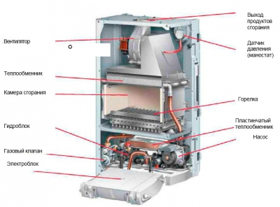
We will not consider the device of double-circuit boilers with an accuracy of a screw, since it is enough for us to understand the purpose of the main components. Inside the cauldron we will find:
Device models with two circuits: heating and DHW circuit.
- A burner located in an open or closed combustion chamber is the heart of any heating boiler. It heats the coolant and generates heat for the operation of the DHW circuit. To ensure accurate maintenance of the set temperature, it is endowed with an electronic flame modulation system;
- Combustion chamber - the above burner is located in it. It can be open or closed. In a closed combustion chamber (or rather, above it) we will find a fan responsible for forcing air and for removing combustion products. It is he who is the source of quiet noise when the boiler is turned on;
- Circulation pump - provides forced circulation of the coolant through the heating system and during the operation of the DHW circuit. Unlike the combustion chamber fan, the pump is not a source of noise and operates as silently as possible;
- Three-way valve - it is this thing that is responsible for switching the system to the hot water generation mode;
- The main heat exchanger - in the device of a double-circuit wall-mounted gas boiler, it is located above the burner, in the combustion chamber. Here, the heating medium used in the heating circuit or in the DHW circuit for heating water is heated;
- Secondary heat exchanger - it is in it that hot water is prepared;
- Automation - it controls the parameters of the equipment, checks the temperature of the coolant and hot water, controls the modulation, turns on and off various nodes, controls the presence of a flame, fixes errors and performs other useful functions.
In the lower part of the buildings there are branch pipes for connecting the heating system, pipes with cold water, pipes with hot water and gas.
Some models of gas double-circuit boilers use dual heat exchangers. But the principle of operation remains almost the same.
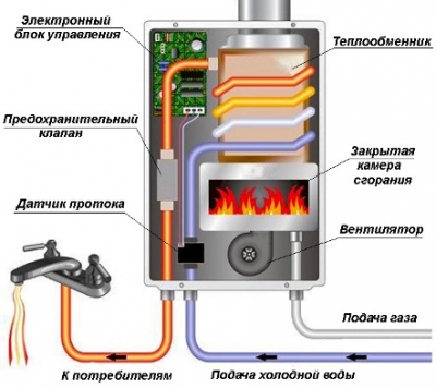
It can be seen that the gas column device differs only in the absence of a heating circuit.
We found out the device of a double-circuit wall-mounted gas boiler - it seems a little complicated, but if you understand the purpose of certain nodes, then the difficulties will disappear. Here we can note the similarity with a gas instantaneous water heater, from which a burner with a heat exchanger remains here. Everything else is taken from wall-mounted single-circuit boilers. The undoubted advantage is the presence of a built-in piping - this is an expansion tank, a circulation pump and a safety group.
When analyzing the principle of operation and the device of a gas double-circuit boiler, it should be noted that the water from the DHW circuit never mixes with the coolant. The coolant is poured into the heating system through a separate pipe connected to the heating. Hot water is prepared by part of the coolant circulating through the secondary heat exchanger. However, we will talk about this a little later.
Water level sensors
These sensors are installed in a well, borehole, tank.It is advisable to use them with submersible pumps, although they are compatible with surface pumps. There are two types of sensors - float and electronic.
float
There are two types of water level sensors - for filling the tank (protection against overflows) and for emptying - just protection against dry running. The second option is ours, the first is needed when filling out. There are also models that can work this way and that, and the principle of operation depends on the connection scheme (included in the instructions).

The principle of operation when used to protect against dry running is simple: as long as there is water, the float sensor is pulled up, the pump can work as soon as the water level has dropped so much that the sensor has dropped, the contactor opens the pump power circuit, it cannot turn on until until the water level rises. To protect the pump from idling, the float cable is connected to a break in the phase wire.
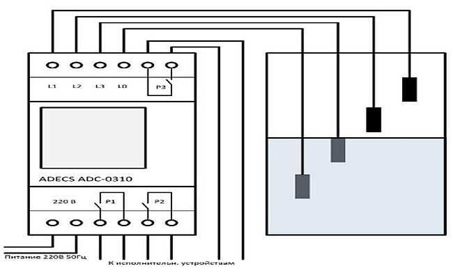
Level control relay
These devices can be used not only to control the minimum water level and dry running in a well, well or storage tank. They can also control overflow (overflow), which is often necessary when there is a storage tank in the system, from which water is then pumped into the house or when organizing pool water supply.
Electrodes are lowered into the water. Their number depends on the parameters they track. If you only need to monitor the presence of a sufficient amount of water, two sensors are enough. One - falls to the level of the minimum possible level, the second - the base - is located a little lower. The work uses the electrical conductivity of water: while both sensors are immersed in water, small currents flow between them. This means that there is enough water in the well / well / container. If there is no current, it means that the water has dropped below the minimum level sensor. This command opens the power supply circuit of the pump and it stops working.
These are the main ways in which protection against dry running of the pump is organized in the water supply systems of a private house. There are also frequency converters, but they are expensive, so it is advisable to use them in large systems with powerful pumps. There they quickly pay off due to energy savings.
The device is designed to automatically turn off surface, borehole pumps, automatic water supply stations in the absence of water in the water intake systems. Switching off pumps and stations ensures their protection against damage as a result of operation without water (dry running mode). Serves to control any electric pumps operating from a single-phase 220 V network, with a power of up to 1.5 kW. The device is installed in the line of the pressure pipeline. In this case, the power supply of the pump is connected to the device, and the power cable is connected to the 220V electrical network. The place of installation of the device must be protected from the risk of water flooding, in a well-ventilated area.
OPERATING LIMITATIONS:
- Working environment temperature: 0°C - 110°C
- Maximum allowable pressure-6 Bar
- Connection 1″ (external and internal)
- The maximum allowable water flow is 100 l/min
DESIGN FEATURES:
- Switching voltage - 220 -240V ~ 50Hz
- Maximum working current: 10A
- Degree of protection - IP65
- Restart - automatic
- Shutdown condition - flow less than 2 l/min
The technical characteristics of the goods and photos may differ from those indicated on the site, specify the technical characteristics of the goods at the time of purchase and payment. All product information on this site is for reference only.
Devices with a horizontal arrangement of plates
The water flow sensor for this type of boiler is suitable for a wide variety of pumps. The conductivity of the models depends on the dimensions of the chamber itself, as well as the channel. Additionally, the diameter of the fitting is taken into account. Many experts recommend installing two-chamber modifications.Their pumping force, as a rule, does not fall below 5 N. The protection system is quite often used by the P50 series. All this suggests that the manufacturer guarantees a high degree of sealing and overall reliability.
When choosing a device, it is important to evaluate the parameters of the valve. If it is made of ordinary plastic, then it is not able to last for a long time.
Copper counterparts perform well, but are expensive. The main flask of the sensors is made of plastic. Very rarely there are modifications with transitional contacts. Relay modifications boast high conductivity. They are not afraid of overload. And they use high-quality protection systems.
The water supply system of a private house is impossible without a pump. But it must somehow be turned on and off, to ensure that it does not work in the absence of water. The water pressure switch is responsible for turning the pump on and off, and protection against dry running of the pump should monitor the presence of water. How to implement this protection in different situations and consider further.
Payment for goods
Payment by credit card - payment for goods by credit card is carried out ONLY at the pickup point.
Cash payment - payment for the goods is carried out in cash to the courier. Payment is accepted in Russian rubles strictly in accordance with the price indicated in the sales receipt. There is a 3% discount for self-delivery.
Cashless payment - payment for goods by bank transfer is possible for all legal entities and individuals. After receiving the order, you will be sent an invoice by e-mail or fax.
Please note that our company is NOT a VAT payer
FLU-25 is a traditionally reliable water flow control in heating and water supply systems. Produced in a factory in Germany.
The flow switch FLU25 is used to control the presence of water flow in an independent heating system with forced circulation, up to the minimum flow rates.
Depending on the connection scheme, the flow switch can turn on or turn off the corresponding element of the autonomous heating system when the coolant flow disappears or appears. For example, if the circulation pump is switched off, the burner may be switched off. The flow switch can also be used to protect the circulation pump from running dry.
The FLU-25 flow switch has a metal housing and can be installed in rooms with high humidity. The presence of a spring bellows (bellows seal) makes the flow switch also suitable for diesel fuel.
The package includes plates (lamellas) of various lengths for pipes from 1 to 8 inches.
Installation:
To ensure perfect operation, the flow switch must be installed on a horizontal pipeline so that the plate (lamella) is vertical. The distance between the pipe and the device must be at least 55 mm, and the distance to subsequent fittings, bends or fittings on the pipeline must be at least 5 DN. The flow switch must be oriented so that the direction of the arrow on the body corresponds to the direction of flow in the pipeline.
If there are foreign mechanical impurities in the coolant and high contamination, a mechanical filter should be installed in front of the flow switch.
Specifications:
Microswitch (relay) 6 A - 220 V
Maximum working pressure 10 bar.
Maximum coolant temperature 110°C
Maximum ambient temperature 60°C
Protection class IP 54, inner diameter of cable entry 6mm (included)
External thread G1
Mounted on pipes Du25…Du-200mm
Flow switch adjustment:
The table below gives the required lamella length according to the pipe diameter.
The operating threshold (operating point) is determined by the tension of the spring (10), the setting of the screw (8) and the length of the lamella (A).
The table shows the pipe diameters, corresponding lamella lengths and water flow in m3/h at which the microswitch contacts close or open, both at the minimum setting (screw tightly tightened) and at the maximum value setting (screw completely loosened).
The device is shipped with a tight calibration screw (minimum setting). Contact 1 - 2 is open. After starting the pumps or when setting the nominal water flow, the lamella must move in the direction of the water flow, as a result of which contact 1 - 2 closes and the burner starts to work.
If the lamella does not move, this means that the water flow is too low and the device cannot react. However, in practice this is almost completely excluded, since the value of the water flow is usually significantly higher than the established minimum value (for example, 6.3 m3 / h at 3" pipe diameter). If the actual water flow is known, the device can be fine-tuned (see table in the Specification section, PDF file).
Flow switches in heating systems with simple ON-OFF control do not require precise calibration. It is enough to set the minimum value so that the contact that controls the burner closes as soon as the set water flow is reached (see table).
Read more in the SPECIFICATION (PDF file below)
The principle of operation of the boiler and its device
Image 1. Hydraulic diagram of a double-circuit boiler in heating mode.
Gas appliances with two heating circuits have the following principle of operation. The heat of the burnt natural gas is transferred to the heat exchanger, which is located above the gas burner. This heat exchanger is included in the heating system main, that is, the heated water in it will circulate through the heating system. Water circulation is carried out by means of a pump built into the boiler. For the preparation of hot water, the double-circuit device is equipped with a secondary heat exchanger.
The presented diagram in PICTURE 1 shows the ongoing work processes and equipment arrangement:
- Gas-burner.
- Circulation pump.
- Three-way valve.
- DHW circuit, plate heat exchanger.
- Heating circuit heat exchanger.
- D - input (return) of the heating system for heating;
- A - supply of ready-made coolant for heating appliances;
- C - cold water inlet from the main;
- B - output of ready hot water for sanitary needs and domestic use.
The principle of preparing water for domestic hot water is as follows: the heated water in the first heat exchanger (5), which is located above the gas burner (1) and is designed to heat the heating circuit, enters the second plate heat exchanger (4), where it transfers its heat to the domestic hot water circuit.
As a rule, double-circuit boilers have a built-in expansion tank to compensate for changes in the volume of the coolant.
The scheme of a double-circuit boiler allows you to produce hot water and heat it for heating only in certain modes.
The design of a double-circuit gas boiler.
Using the boiler for both domestic hot water and heating at a certain point in time is not possible. For example, during operation of the device, the heating system is heated at a given temperature, the process of maintaining the temperature is controlled by the automatic boiler, and the circulation of the coolant through the heating network is carried out by a pump.
At a certain moment, the hot water tap for domestic needs is opened, and as soon as the water begins to move along the DHW circuit, a special flow sensor installed in the boiler is activated. With the help of a three-way valve (3), the water flow circuits in the boiler are reconfigured. Namely, the water heated in the heat exchanger (5) ceases to flow into the heating system and is supplied to the plate heat exchanger (4), where it transfers its heat to the DHW system, that is, the cold water that has arrived from the pipeline (C) is heated through the pipeline (B) served to consumers of an apartment or house.
At this moment, the circulation goes in a small circle and the heating system does not heat up during the use of hot water. As soon as the tap on the DHW intake is closed, the flow sensor is triggered and the three-way valve opens the heating circuit again, further heating of the heating system occurs.
Most often, the scheme of the device of a double-circuit gas boiler implies the presence of a plate heat exchanger. As already mentioned, its purpose is to transfer heat from the heating circuit to the water supply circuit. The principle of such a heat exchanger is that sets of plates with hot and cold water are assembled into a package where heat transfer occurs.
The connection is made in a hermetic way: this prevents the mixing of liquids from different circuits. Due to the constant change in temperature, processes of thermal expansion of the metal from which the heat exchanger is made occur, which contributes to the mechanical removal of the resulting scale. Plate heat exchangers are made of copper or brass.
Connection diagram for a double-circuit boiler.
There is a double-circuit boiler scheme, which includes a combined heat exchanger.
It is located above the gas burner and consists of double tubes. That is, the heating circuit pipe contains a hot water pipe inside its space.
This scheme allows you to do without a plate heat exchanger and slightly increase the efficiency in the process of preparing hot water.
The disadvantage of boilers with a combined heat exchanger is that scale is deposited between the thin walls of the tubes, as a result of which the operating conditions of the boiler deteriorate.
Checking the water heater thermostat
You can check the thermostat using a multimeter.
The check is carried out as follows:
- The multimeter flag must be turned to the resistance measurement mode.
- Next, connect the contacts of the multimeter to the contacts of the thermostat.
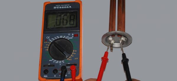
Correct connection of the multimeter
- If an infinite value appears on the display of the multimeter, then the thermostat will have to be completely replaced, it cannot be repaired.
- If resistance appears on the display, then you should check the box to a lower value, and then warm up the thermostat pipe with a lighter, if it works properly, then the resistance will increase sharply and a protective reaction will work.
DIY repair
Some problems can be fixed on your own. The main thing is to follow our recommendations.
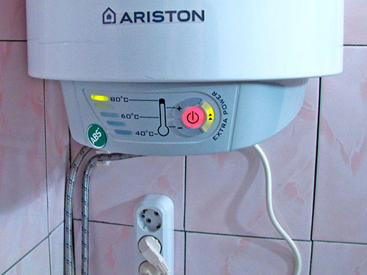
The water heater does not turn on
First of all, check if there is voltage in the network. You can check this with a screwdriver with an indicator: it should light up on the “Phase”, but not on “Zero” and “Earth”. If the cable insulation is broken, repair is not recommended. It is better to replace the element immediately, but make sure that the new cable matches the old one in terms of parameters.
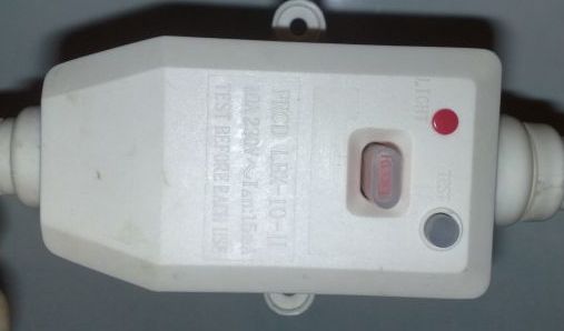
A short circuit or lack of grounding leads to a permanent shutdown of the RCD. The breakdown of the heating element on the body also leads to similar consequences. In this case, the element is diagnosed and replaced.
The RCD could be broken. To confirm your guesses, press RESET on the instrument panel. Is the light bulb glowing? So food is being served. Then press TEST and then RESET again. If the indicator lights up again, the RCD is working normally.
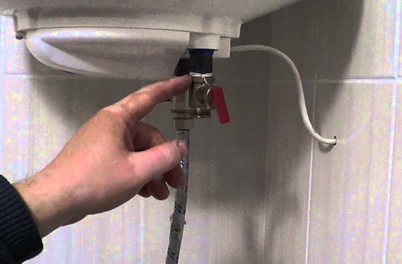
Boiler does not heat water
Check the tightness of the contacts between the plug and socket. If everything is in order and the voltage is supplied normally, you need to check the heating element. Do you have a storage boiler? Then drain the water first. A volume of water of 50-80 liters can be removed through the faucet. 100 liters or more is best drained with a valve.
Remove the case from the wall. Now you need to pull out the flange to which the heating element is attached. In Ariston models of 80 liters, the flange fastens with only one bolt. In other cases, you will have to unscrew 5 bolts.
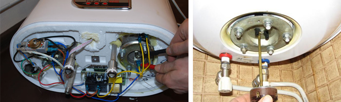
Disassembly is done like this:
- Scroll the flange along the axis.
- Take it out of the tank.
- Heater diagnostics is carried out with a multimeter. Read more in the article: "Replacing a heating element in a water heater".
- If the multimeter needle moves, the part is good. Is it in place? You need to put in a new one.
Have you noticed that the water heats up longer than usual? This does not mean that the heater is broken. Perhaps the reason is scale: over time, it grows in a thick layer and interferes with normal heat transfer. Clean the element with special means.
Lack of heat may indicate a broken thermostat. Perform a restart on the boiler panel. If the appliance cannot be restarted, the thermostat is defective.
A tester will help diagnose a breakdown more accurately:
- Set the multimeter to the maximum position.
- Attach the probes to the thermostat contacts (located next to the heating element).
- Does the arrow on the screen move? The device is working.
There is another option:
- Heat the thermostat with a lighter.
- Set the multimeter to "minimum".
- Attach the probes to the contacts.
- If the arrow moves away from zero, then the part is functioning normally.
In the event of a malfunction, the thermostat must be replaced. Disconnect the wiring from the part, pull it out of the hole.
Installation is carried out in the reverse order.
tank leaking
Found a leak? Carefully inspect all connections, hoses. If everything is in order, you need to inspect the tank itself. A leak can occur as a result of strong water pressure. If the body is swollen, check and replace the relief valve.
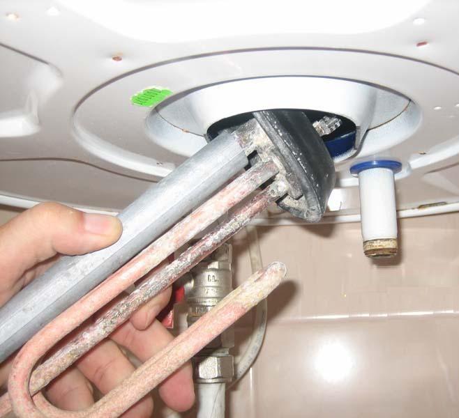
If the tank "ran", it will not be difficult to disassemble it for verification. Open the top cover of the product and look inside. Are the walls and heater covered with scale? We need to clean the equipment. Pull out the heating element and the anode (they are located nearby).
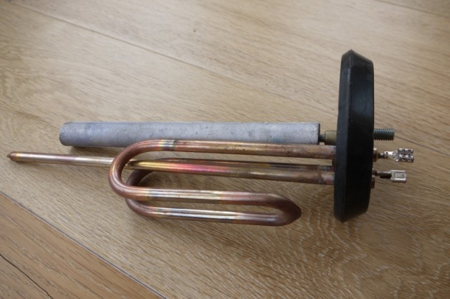
Carefully clean scale from all surfaces and walls of the tank. Then rinse with a solution of the Antinakipin type. Install the heater and a new magnesium anode in the cleaned tank.
The gasket that secures the parts from below can also leak. Inspect it and replace it.
All these works can be done independently.
Important: disconnect equipment from the network before starting work