Calculation of flow and pressure of water
Well pump selection table.
The choice of pumping equipment should be carried out, taking into account the expected water consumption for the site and the house:
- for a shower - 0.2-0.7 l / s;
- for a jacuzzi - 0.4-1.4 l / s;
- for a bathtub with standard mixers - 0.3-1.1 l / s;
- for sinks, sinks in the kitchen and bathrooms - 0.2-0.7 l / s;
- for taps with sprayers - 0.15-0.5 l / s;
- for the toilet - 0.1-0.4 l / s;
- for a bidet - 0.1-0.4 l / s;
- for a urinal - 0.2-0.7 l / s;
- for a washing machine - 0.2-0.7 l / s;
- for a dishwasher - 0.2-0.7 l / s;
- for watering taps and systems - 0.45-1.5 l / s.
To calculate the pressure, it must be remembered that the pressure in the pipes should be 2-3 atmospheres, and the excess pump power should not exceed 20 m. For example, the immersion depth is 10 m from the ground level, then the calculated loss will be 3 m. In this case the pressure is calculated as follows: well depth + water supply along the vertical shaft + height above the ground level of the upper draw-off point + overpressure + calculated losses. For this example, the calculation will be as follows: 15 + 1 + 5 + 25 + 3 = 49 m.
When summing up the approximate consumption per unit of time, one must also take into account the fact that 5-6 taps are opened at the same time or a similar number of draw-off points are used. The number of residents, the presence of greenhouses on the site, the garden and other parameters are taken into account. Without these data, the correct selection is impossible.
Section 2. Structural calculation of a centrifugal pump. .eighteen
-
Definition
speed factor and type
pump 20 -
Definition
impeller outer diameter
D2 20 -
Definition
pump impeller width at the outlet
from pump b2……….20 -
Definition
reduced diameter of the entrance to the working
wheel D1 20 -
Definition
impeller throat diameter
DG 20 -
Choice
impeller width inlet head
to pump b1 21 -
Choice
impeller blade angles
at the exitand at the entrance
21 -
Choice
number of impeller blades and
blade angle adjustmentand
21 -
Construction
for volute pump 22
2.10. Choice
dimensions of the confuser at the inlet to the pump and
outlet diffuser
from
pump 23
2.11. Definition
actual design head,
developed
designed
pump, (Ndn)R 23
Section 4 Calculation of the theoretical pump curve 25
-
theoretical
pump head characteristic 26 -
theoretical
hydraulic pump characteristic
power….27 -
theoretical
pump characteristic according to K.P.D 27
Questions
to term paper 31
Bibliographic
list 32
Target,
content and background data for the course
work.
aim
coursework is designing
hydraulics and hydraulic drive
systems
automotive liquid cooling
engine.
Content
the calculated part of the course work.
-
Hydraulic
calculation of the engine cooling system. -
Constructive
calculation of a centrifugal pump. -
Payment
theoretical characteristics of the pump.
Initial
coursework data.
-
Power
engine Ndv=
120,
kW. -
Share
engine power taken on
cooling= 0,18
-
Temperatures
coolant (coolant)
at the engine outlet t1
=
92, °С and at the radiator outlet t2
=
67, °С. -
Frequency
rotation of the impeller in the pump n
= 510, rpm. -
Estimated
pump head HPn
=
1,45,
m. -
Estimated
pressure loss in the cooling device
engine
=
0,45,
m. -
Estimated
loss of pressure in the radiator=
0,3,
m. -
Diameter
(internal) lower manifold
engine cooling devices d1
=
40,
mm.
9. Diameters
(internal) radiator manifolds d2
=
50 mm.
10.
Internal diameters of all pipelines
hoses d3
=
15,
mm.
11.
Total length of pipelines of the site
hydraulic lines, the first in the direction of travel
from
engine
to radiator L1
=
0,7,
m.
12.
The total length of the pipelines of the second
section of hydraulic lines L2
=
1,5,
m.
DESCRIPTION
ENGINE COOLING SYSTEMS.
System
engine cooling consists (Fig. 1) of
centrifugal pump 1, device
engine cooling 2, radiator for
coolant cooling flow
air 3, thermal valve 4 and connecting
pipelines - hydraulic lines 5. All
these elements of the system are included in
the so-called "big" cooling circle.
There is also a "small" cooling circle, when
coolant does not enter the radiator.
The reasons for having both "big" and
"small" cooling circles are represented
in special disciplines. calculation
subject only to the "great" circle, as
calculated path of movement of the cooling
liquid (coolant).
Device
engine cooling consists of a "shirt"
cylinder head cooling
engine (2a), cooling jackets
side walls of cylinders
engine (in the form of vertical strokes
cylindrical shape, located
on two sides of the engine) (26) and two
cylindrical collectors for collecting
coolant (2c). Representation
side wall cooling jackets
cylinders in the form of vertical strokes
is conditional, but close enough
to reality and
representation of the element in question
engine cooling devices
would be used when conducting
hydraulic calculation system
engine cooling.
Radiator
3 consists of upper (Za) and lower (36)
collectors, vertical pipes
(Sv), along which the coolant moves
from the top manifold to the bottom.
The thermal valve (thermostat) is
automatic throttle
device designed for
changes in the movement of the coolant or
on
"large" or "small" circles.
Devices and principles of operation of the radiator
and thermal valve (thermostat) are studied
in special disciplines.
coolant
when it moves in a "big" circle
goes the following way:
centrifugal pump - cooling jacket
cylinder covers - vertical strokes in
engine walls - lower manifolds
cooling devices
engine - a node connecting two streams
- thermal valve - upper manifold
radiator
- radiator tubes - lower manifold
radiator - inlet to the pump. Along the way
a number of "local" resistances are overcome
in the form of sudden expansions or contractions
flow, 90° turns, as well as
throttle device (thermal valve).
Everything
hydraulic lines of the engine cooling system
made of technically smooth
pipes, and the inner diameters of the pipes
throughout the hydraulic lines
are the same
and equal to d3.
The task also contains values
lower manifold diameters
engine cooling devices d1
and both radiator manifolds d2,
as well as
length of radiator manifolds lR=0,5
m.
coolant
in the engine cooling system is taken
coolant,
which at a temperature of +4 °C density
is
=1080
kg/m3
, and the kinematic
viscosity
m2/s.
It can be antifreeze fluids,
"Tosol", "Lena", "Pride" or others.
1 Pump parameters.
Innings
condensate pump is determined
in the following way:
 ,
,
 ;
;
pressure
condensate pump calculated
according to the formula for the scheme with a deaerator:
 ,
,
 ;
;
Head of condensate
pump is calculated by the formula for
schemes without deaerator:
 ,
,
 ;
;
Members included in
formula data:
 ,
,
where
 is the density of the pumped liquid;
 ,
,
where  —
—
coefficient of hydraulic resistance;
 —
—
number
Reynolds;
in turn, the fluid velocity
expressed as:
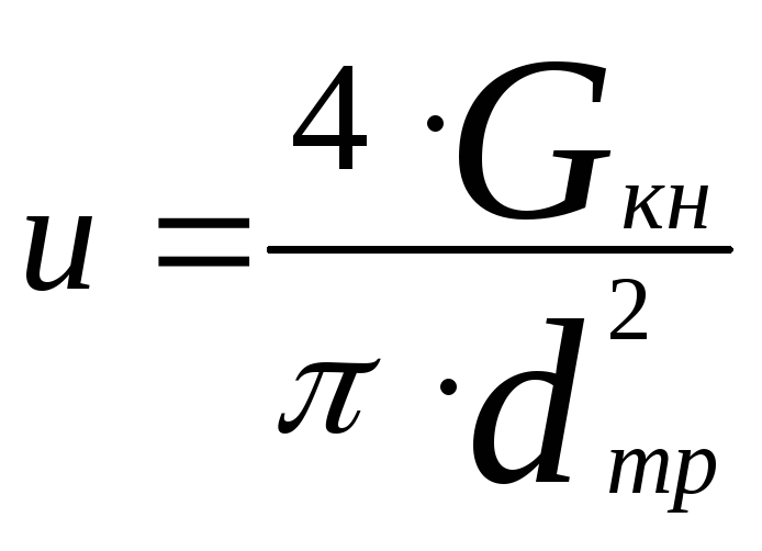 ,
,
 ;
;
Depending on the
the obtained value of the Reynolds number
calculate the coefficient of hydraulic
resistance according to the following formulas:
a)
With the value of the number
 — laminar flow regime:
 ;
;
b)
With the value of the number

— turbulent flow regime:
 —
—
for smooth pipes
 —
—
for rough
pipes, where
 —
—
equivalent diameter.
v)
With the value of the number
 —
—
area of hydraulically smooth pipes:
Payment

is carried out according to the Colebrook formula:
 ;
;
 ,
,
 - speed
pumped liquid;
Innings
feed pump determined
in the following way:
 ,
,
 ;
;
Nutrient pressure
pump is calculated by the formula for
schemes with a deaerator:
 ,
,
 ;
;
pressure
feed pump is calculated by
formula for a circuit without a deaerator:
 ,
,
 ;
;
Pump calculation
Initial data
Make the necessary calculations and select the best version of the pump for supplying the R-202/1 reactor from the E-37/1 tank under the following conditions:
Wednesday - Gasoline
Flow rate 8 m3/h
The pressure in the tank is atmospheric
Reactor pressure 0.06 MPa
Temperature 25 °C
· Geometric dimensions, m: z1=4; z2 =6; L=10
Determination of the physical parameters of the pumped liquid
Density of gasoline at temperature:
Place for the formula.
At
In this way
Kinematic viscosity:
Dynamic viscosity:
Pass
Saturated steam pressure:
Determining the required pump head
a) Determination of the geometric height of the liquid rise (the difference between the liquid levels at the outlet and the inlet to the tank, taking into account the overcoming of the height of the reactor):
(26)
where Z1 is the liquid level in the E-37/1 tank, m
Z2 is the liquid level in the R-202 column, m
b) Determination of pressure losses to overcome the pressure difference in the receiving and pressure tanks:
(27)
where Pn is the absolute discharge pressure (excess) in the E-37/1 tank, Pa;
Pv is the absolute suction pressure (excess) in the R-202/1 reactor, Pa
c) Determination of pipeline diameters in the suction and discharge paths
Let's set the recommended speed of fluid movement:
In the discharge pipeline, the injection velocity Wн = 0.75 m/s
In the suction pipeline, the suction velocity Wb = 0.5 m/s
We express the diameters of the pipelines from the formulas for the fluid flow rate:
(28)
(29)
Where:
(30)
(31)
Where d is the diameter of the pipeline, m
Q is the flow rate of the pumped liquid, m3/s
W is the fluid flow rate, m/s
For further calculation of the diameters, it is necessary to express the flow rate Q in m3/s. To do this, divide the given flow rate in hours by 3600 seconds. We get:
According to GOST 8732-78, we select the pipes closest to these values.
For suction pipe diameter (108 5.0) 10-3 m
For discharge pipeline diameter (108 5.0) 10-3 m
We specify the fluid flow rate according to the standard internal diameters of pipelines:
(32)
Where - the inner diameter of the pipeline, m;
- outer diameter of the pipeline, m;
— pipeline wall thickness, m
The true fluid flow rates are determined from expressions (28) and (29):
We compare the true fluid flow rates with the given ones:
d) Determination of the fluid flow regime in pipelines (Reynolds numbers)
The Reynolds criterion is determined by the formula:
(33)
Where Re is the Reynolds number
W is the fluid flow velocity, m/s; — inner diameter of the pipeline, m; — kinematic viscosity, m2/s
Suction pipeline:
Discharge pipeline:
Since the Re number in both cases exceeds the value of the zone of transition from the laminar regime of fluid flow to turbulent, equal to 10000, this means that the pipelines have a developed turbulent regime.
e) Determination of friction resistance coefficient
For a turbulent regime, the coefficient of friction resistance is determined by the formula:
(34)
For suction pipe:
For discharge pipeline:
f) Determination of local resistance coefficients
The suction pipe contains two through valves and a 90-degree elbow. For these elements, according to the reference literature, we find the coefficients of local resistance: for a through valve, for a knee with a turn of 90 degrees,. Taking into account the resistance that occurs when the fluid enters the pump, the sum of the coefficients of local resistance in the suction tract will be equal to:
(35)
The following elements are located in the discharge pipeline: 3 through valves, check valve \u003d 2, diaphragm, heat exchanger, 3 elbows with a turn of 90 degrees. Taking into account the resistance that occurs when the liquid leaves the pump, the sum of the coefficients of local resistance in the discharge path is equal to:
g) Determination of pressure losses to overcome friction forces and local resistances in the suction and discharge pipelines
We use the Darcy-Weisbach formula:
(37)
where DN is the pressure loss to overcome friction forces, m
L is the actual length of the pipeline, m
d is the inner diameter of the pipeline, m
- the sum of local resistances on the path under consideration
Hydraulic resistance in the suction pipe:
Hydraulic resistance in the discharge pipeline:
i) Determining the required pump head
The required pressure is determined by adding the calculated components, namely the geometric difference in the levels in the furnace and in the column, the losses to overcome the pressure difference in the furnace and in the column, as well as local hydraulic resistances in the suction and discharge pipelines, plus 5% for unaccounted losses.
(40)
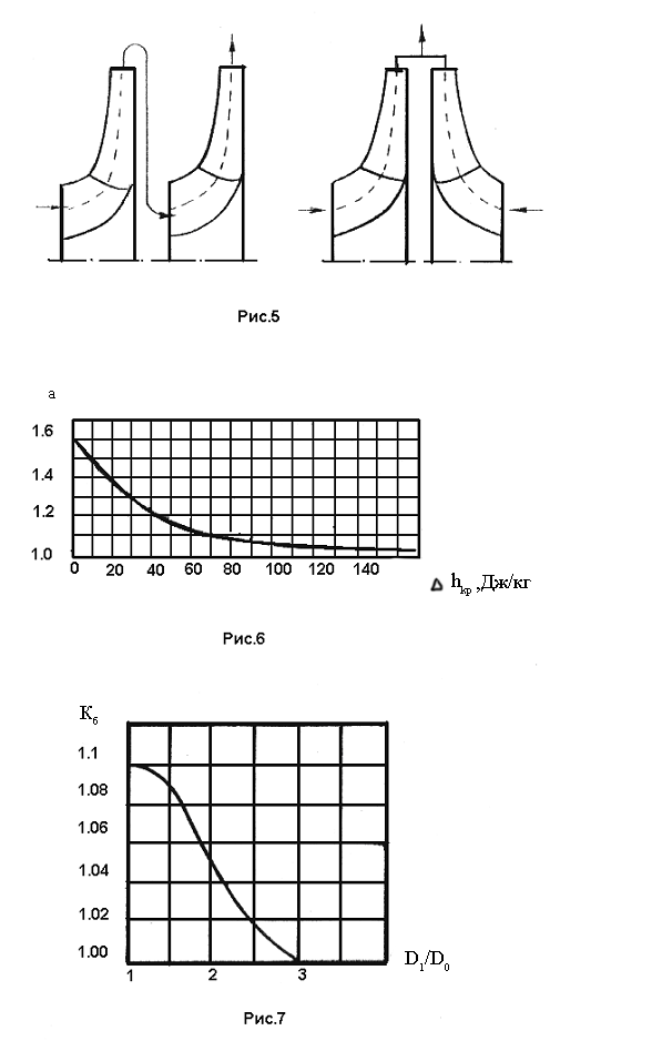
2 Step parameters.
Multiwheel
centrifugal pumps perform with
consistent
or parallel
connection of impellers (see fig. 5
left and right, respectively).
Pumps
with serial connection of workers
wheels are called multistage.
The head of such a pump is equal to the sum of the heads
individual stages, and the pump flow
is equal to the feed of one stage:
 ;
;
 ;
;
where
 –
–
number of steps;
 ,
,
 ;
;
Pumps
with parallel connection of wheels is accepted
consider multithreaded.
The head of such a pump is equal to the head of one
steps, and the feed is equal to the sum of the feeds
individual elementary pumps:
 ;
;  ;
;
where
— number
flows (for ship pumps it is accepted
no more than two).
Number of steps
limited to maximum pressure
created by one stage (usually not
exceeds 1000 J/kg).
We define
critical
cavitation energy reserve
without
deaerator
for
feed pump:
 ;
;
for condensate
pump:
 ;
;
Critical
cavitation energy reserve with
deaerator
for nutritional
pump:
 ;
;
for condensate
pump:
 ;
;
where
 is the liquid saturation pressure at
set temperature;
— hydraulic losses of the suction pipeline;

— coefficient
reserve,
which is accepted
 .
.
 ;
;
 ;
;
 —
—
speed factor
pump (see Fig. 7);
 or
or

- respectively
for cold fresh and sea water;
Coefficient
reserve 
is chosen so
what are the ingredients in his work
satisfy graphic dependencies
 and
and .
.
The resulting value of this coefficient
will be clarified when finding the calculated
ratios  further according to the proposed
methodology. (Note that the proposed
figures 6 and 7 graphic dependencies
are predominantly nutritional
pumps, so that in case of failure
set conditions for nutritional
pumps, we allow an increase in the final
limit value of the coefficient
reserve  to a value that
would eventually satisfy  and
and
 ).
).
Further
define maximum
permissible speed
impeller:

 ,
,
where
 —
—
cavitation
speed factor,
which is chosen based on the purpose
pump:
 —
—
for
pressure and fire pump;
 -for
-for
feed pump;
 —
—
for
feed pump with booster
step;
 —
—
for
condensate pump;
 —
—
for
pump with pre-engineered axial wheel;
Let's define
working
rotational speed
pump wheels:

 ,
,
where
 —
—
coefficient
speed,
taking the following values:
 —
—
for
pressure and fire pump;
 —
—
for
feed pump with booster stage;
 —
—
for
feed pump;
 —
—
for
condensate pump;
Condition
correct choice of coefficient
speed: harmonization
rotational speeds by inequality 
(and
 not
not
less than 50 should be taken).
Estimated
innings
wheels can be found by the expression:
 ,
,
where
 —
—
volumetric efficiency, which is found as:
 ,
,
where
 —
—
takes into account the flow of liquid through
front seal;
Theoretical
pressure
is found according to the formula:
 ,
,
where
 — hydraulic
efficiency, which the
defined as:
 ,
,
where
 —
—
reduced
diameter
entrance to the impeller; accepted (see fig. 8). Note
that hydraulic losses occur
due to the presence of friction in the channels of the flow
parts.
Mechanical
efficiency
find by the formula:
 ,
,
where
 takes into account losses
friction energy of the outer surface
wheels on the pumped liquid
(disk friction):
 ;
;
 —
—
takes into account energy losses due to friction in
bearings and stuffing boxes
pump.
General
efficiency pump
defined as:
 ;
;
Efficiency of ships
centrifugal pumps lies within
from 0.55 to 0.75.
Consumed
power
pump and maximum
power
at overloads respectively
defined as:

 ;
;

 ;
;
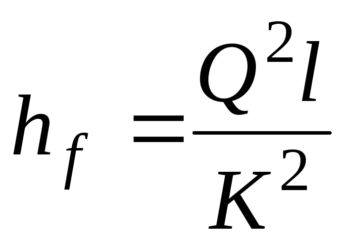
3.1 Hydraulic calculation of a long simple pipeline
Consider long pipelines, i.e.
those in which the pressure loss on
overcoming local resistance
negligible compared to
head loss along the length.
For hydraulic calculation we use
formula ( ), to determine the losses
pressure along the entire length of the pipeline

P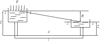 growth
long pipeline is
pipeline with constant diameter
pipes operating under pressure H (figure
6.5).
Figure 6.5
To calculate a simple long pipeline
with a constant diameter, write
Bernoulli's equation for sections 1-1 and 2-2
 .
.
Speed 1=2=0,
and the pressureP1=P2=Pat,then the Bernoulli equation for these
conditions will take the form
 .
.
Therefore, all pressure Hspent on overcoming hydraulic
resistance along the entire length of the pipeline.
Since we have a hydraulically long
pipeline, then, neglecting local
head loss, we get
 .
.
(6.22)
But according to formula (6.1)
 ,
,
where

Thus, the pressure
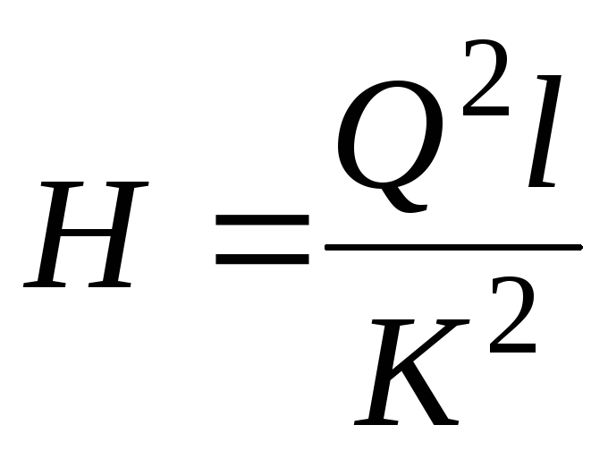
 (6.24)
Calculation of the parameters of the hydraulic pump
For safe operation of the hydraulic line, we accept a standard pressure of 3 MPa. Let's calculate the parameters of the hydraulic drive at the accepted pressure value.
The performance of hydraulic pumps is calculated by the formula
V = ,(13)
where Q is the required force on the rod, Q = 200 kN;
L is the length of the working stroke of the hydraulic cylinder piston, L = 0.5 m;
t is the working stroke time of the hydraulic cylinder piston, t = 0.1 min;
p is the oil pressure in the hydraulic cylinder, p = 3 MPa;
η1 - hydraulic system efficiency, η1 = 0.85;
V = = 39.2 l / min.
According to the calculation, we select the pump NSh-40D.
10 Motor calculation
The power consumed to drive the pump is determined by the formula:
N = ,(14)
where η12 is the overall efficiency of the pump, η12 = 0.92;
V – productivity of the hydraulic pump, V = 40 l/min;
p is the oil pressure in the hydraulic cylinder, p = 3 MPa;
N = = 0.21 kW.
According to the calculation data, to obtain the required pump performance, we select the AOL2-11 electric motor, with a rotation speed of n = 1000 min−1 and a power of N = 0.4 kW.
11 Calculation of the toe for bending
The paw toes will experience the greatest bending moment at a maximum load R = 200 kN. Since there are 6 paws, one finger will experience a bending moment from the load R = 200 / 6 = 33.3 kN (Figure 4).
Finger length L = 100 mm = 0.1 m.
Bending stress for circular section:
σ = (15)
where M is the bending moment;
d is the finger diameter;
In the dangerous section, the moment will be
Mizg = R ∙ L / 2 = 33.3 ∙ 0.1 / 2 = 1.7 kN∙m.
Figure 4 - To the calculation of the finger for bending.
The finger in its cross section is a circle with a diameter of d = 40 mm = 0.04 m. Let us determine its bending stress:
σ = = 33.97 ∙ 106 Pa = 135.35 MPa
Strength condition: ≥ σbend.
For steel St 45 allowable stress = 280 MPa.
The strength condition is met, because the allowable bending stress is greater than the actual one.
The necessary parameters of the hydraulic cylinder were calculated. According to the calculation data, a hydraulic cylinder with a piston diameter of 250 mm and a rod diameter of 120 mm was installed. The acting force on the rod is 204 kN. The cross-sectional area of the stem is 0.011 m2.
The calculation of the rod for compression showed that the compression stress is 18.5 MPa and less than the allowable 160 MPa.
The strength calculation of the weld was carried out. The allowable stress is 56 MPa. The actual stress that occurs in the weld is 50 MPa. Seam area 0.004 m2.
The calculation of the parameters of the hydraulic pump showed that the pump performance should be more than 39.2 l / min. According to the calculation, we select the pump NSh-40D.
The calculation of the parameters of the electric motor was carried out. Based on the calculation results, an AOL2-11 electric motor with a rotation speed of n = 1000 min−1 and a power of N = 0.4 kW was selected.
The calculation of the paw toe for bending showed that in the dangerous section the bending moment will be Mb = 1.7 kN∙m. Bending stress σ = 135.35 MPa, which is less than the permissible value = 280 MPa.
Concepts and structure of the services market. Transport services
The broad term "international trade" can be understood not only as a relationship for the sale of goods, but also for services. Services are activities that directly satisfy the personal needs of members of society, households, the needs of various kinds of enterprises, associations, organizations ...
Technological process of engine assembly
Install the cylinder block on the stand and check the tightness of the oil channels. Violation of tightness is not allowed. Install the block but the stand for disassembly - assembly in a horizontal position. Blow out all internal cavities of the cylinder block with compressed air (gun for blowing parts with compressed air ...
Determination of gear ratios of the transfer case
There are two gears in the transfer boxes - high and low. The highest gear is direct and its gear ratio is 1. The gear ratio of the lower gear is determined from the following conditions: - From the condition of overcoming the maximum rise: - From the condition of full use of the coupling mass ...
More about direct water supply method
The system can be organized in different ways. The simplest, but not the most successful, is the option in which water is supplied from a well to places of consumption without additional devices. This scheme implies frequent switching on and off of the pump during operation. Even with a short opening of the tap, the pumping device will start.
The direct water supply option can be used in systems with minimal branching of pipelines, if at the same time it is not planned to live in the building permanently. When calculating the main parameters, some features should be taken into account. First of all, it concerns the generated pressure. Using a special calculator, you can quickly make calculations to determine the outlet pressure.
On the main features of the calculations
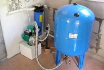
With permanent residence and the presence of a large number of water points in the building, it is best to arrange a system with a hydraulic accumulator, which allows to reduce the number of work cycles. This will have a positive effect on the life of the pump. However, such a scheme is complex in design and requires the installation of an additional capacitance, so sometimes its use is impractical.
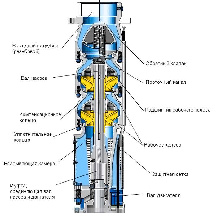
Submersible pump device for a well
With a simplified version, the accumulator is not mounted. The control relay is adjusted so that the suction device is turned on when the tap is opened, and turned off when it is closed. Due to the lack of additional equipment, the system is more economical.
In such a scheme, the pump for the well should:
- ensure a high-quality rise of water directly to the highest point without any interruption;
- overcome without unnecessary difficulties the resistance inside the pipes that run from the well to the main points of consumption;
- create pressure in the places of water intake, which makes it possible to use various plumbing fixtures;
- provide at least a small operational reserve so that the well pump does not work at the limit of its capabilities.
With proper calculations, the purchased equipment will allow you to create a reliable system that provides water supply to the water intake points directly. The final result is given immediately in three quantities, since any of them can be indicated in the technical documentation.
Save Time: Featured Articles Every Week by Mail