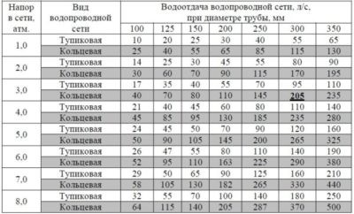
6. BASIC INFORMATION ABOUT HYDRAULIC CALCULATION OF WATER NETWORKS
|
Calculation of water networks When calculating the water supply network, it is assumed that The pressure losses calculated from the calculated flow are equal to External water supply networks are calculated several times: at the maximum hourly consumption per day maximum for the minimum hourly consumption per day of the maximum for the maximum hourly flow rate, taking into account the water supply to At the speed of water movement and Head loss in local resistances due to their smallness Branched water networks are calculated as systems The calculation of ring water supply networks is much more complicated. The calculation of the ring water supply network is reduced to the purpose At the beginning of the calculation on the network diagram, the distribution is planned To calculate the head loss from the starting point of the network up to There are several methods for calculating (linking) ring At present, methods have been developed for calculating ring |
CONTENTS OF THE BOOK: Fundamentals of water supply and sewerage
§ 23. Theoretical foundations of verification hydraulic
calculations plumbing networks. Calibration task calculation
networks is to determine the flow of water in the areas networks at
already known pipe diameters ...
Section 3. WATER SUPPLY AND DISTRIBUTION SYSTEMS (WATER
NETWORKS AND WATER PIPELINES).
Such payment is essentially a verification calculation networks
and bears the name hydraulic linkages networks.
In closed heat supply systems, when for the needs of hot water supply
heats up tap water, usually not softened waterPayment networks formulas are rarely produced due to its large
laboriousness. Usually when hydraulic calculation.
Section 3. WATER SUPPLY AND DISTRIBUTION SYSTEMS (WATER
NETWORKS AND WATER PIPELINES). § 30. Combination of technical and economic calculations
with verification hydraulic calculations networks.
AndriyashevM M. hydraulic calculations
conduits and plumbing networks. M, Stroyizdat, 1964. Mosh n and L. F. Methods of technical and economic calculation plumbing networks.
WATER NETWORKS.
§ 3.10. Special cases of operation of water conduits and networks. hydraulic
blows.
Statement of the problem about calculation plumbing networks. aim calculation
networks is
On the issue of calculating the costs and losses of water in cold hot water supply systems during its production and transportation
Far Eastern enterprise Vodokanalnaladka
Far Eastern Enterprise Vodokanalnaladka LLC offers
Justification services for your company
percent of leaks and unaccounted expenses in the system of cold (hot) water supply.
Practice to establish this
percent in cities and towns of the Far Eastern Federal District indicates that such a value, approved by the relevant authorized structures, is significantly underestimated. Understating the real percentage of expenses and losses leads to the fact that the resource supplying enterprise is forced to bear additional responsibility, including financial, for unsold volumes of water (hot or cold), pay taxes for them, overestimate discharge limits, etc.
Useful water supply is inevitable
accompanied by losses, unaccounted for costs and unproductive waste of water, which
are made up of losses in the production and transportation of water and losses in the internal distribution
water consumer networks.
The amount of these costs depends on many factors:
technical condition of the water supply network of facilities, stability and quality
soils at the base of pipelines, the level of operation, the presence of water treatment facilities, etc.
They are understood as the total volume of water supplied,
spent on the needs of its operation; volumes of water consumed by subscribers, not
having metering devices, as well as all types of water losses from the network.
The amount of losses and unaccounted expenses in
the water supply system of a settlement is the difference between
volumes of water withdrawn from the source of water supply and released water
consumers and is expressed as a percentage.
Ministry
construction and housing and communal services of the Russian Federation issued Order No. 640 / pr dated October 17, 2014 (registered
Ministry of Justice of Russia on February 17, 2015 No. 36064) “On approval of guidelines for
calculation of losses of hot, drinking, technical water in centralized systems
water supply during its production and transportation” (hereinafter Order No. 640). This
the first regulatory legal act on the calculation of leaks and unaccounted for costs in cold and
hot water supply of settlements.
Usually,
major losses
and leaks from networks occur through no fault of the resource supplying organization. These costs may, for the most part, be
leaks, but the useful costs of the enterprise to maintain the operation of technological
water treatment facilities, natural loss of water during its transportation, etc. complete structure
of all expenses and losses make it possible to identify and determine the calculations according to Order No. 640.
The Methodological Guidelines do not provide for the coordination procedure at the stations, therefore, this is not formally necessary.
water in the cold (hot) system
water supply with
production and transportation, should
be approved by order of the head
enterprises and be used in production regulations.
After that, this value can:
apply
in calculations of the balance of water consumption;
be provided
to the Price Committee when justifying the tariff;
prove, incl. before the tax service, reduction of the taxable base when substantiating volumes
sales of water (disposal and discharge of wastewater), etc.
In the event that any authority does not agree with the amount of expenses and losses, then it has the right to officially consider the performed calculations for compliance with the Guidelines. If there are objections, this entity must submit them in writing. After that, it will receive an official
response (to be prepared by us in a written request) with explanations and clarifications. However, given the legislative
novelty, some issues of application of the Guidelines are subject to regulation in practice.
We believe that the performance of this work in the specified format, with an increase in the reasonable rate of leaks
and losses can bring significant cost savings to your enterprise, and reduce a number of administrative claims.
Sincerely.
Director of DV Enterprise Vodokanalnaladka LLC,
Inchagov A. D.
cell phone 8-924-202-82-43
Brief description of the APT system
The purpose of the hydraulic calculation is to determine the water flow for fire extinguishing, the diameters of distribution, supply and supply pipelines and the required required pressure and flow for the pumping unit.
Hydraulic calculation was performed according to the technical data presented in Appendix A (Hydraulic scheme for calculating parameters)
The parameters of the fire extinguishing installation of the shopping center and other premises in the spaces under the stands are adopted in accordance with the requirements of the STU:
- the premises of the object belong to the I group of premises;
— irrigation intensity — 0.12 l/(s m2);
- the minimum area for calculating the water flow - 120 m2;
- duration of water supply - 60 min;
— maximum area protected by one sprinkler — 12 m2;
- water consumption for internal fire extinguishing of the building from fire hydrants is 2 jets with a flow rate of each at least 5 l / s.
The working documentation provides for fire protection by an automatic water fire extinguishing installation with RA1325 Reliable sprinklers with a performance factor of 0.42.
On the main pipeline network, it is planned to install fire hydrants on supply and distribution pipelines with a diameter of DN 65. The arrangement of fire hydrants is made taking into account the irrigation of each point of the protected premises with two jets with a compact jet height of at least 12 m for the premises of the building. At the same time, the flow rate from one fire hydrant is at least 5.2 l / s, and the required pressure at the fire hydrant is at least 19.9 m of water. Art. (according to Table 3 SP10.13130.2009).
The pipelines of the fire extinguishing installation are made of electric-welded and water-gas pipes according to GOST 10704-91 and GOST 3262-75 of various diameters.
The source of cold water supply of the projected object is the projected conduit. The pressure in the existing water supply network is 2.6 atm. (26.0 m).
The estimated area for determining the parameters of the fire extinguishing pumping station was taken at elevation +21.600 (6th floor), the location of the distribution pipeline at elevation +28.300 (under the ceiling) with the installation position of the sprinklers vertically upwards. The section was accepted for calculation due to the fact that it is the most remote, dead-end and highly elevated in relation to other sections of this section.
The internal fire water pipeline is made combined with sprinkler water fire extinguishing, a common pumping group.
To determine the parameters of the fire extinguishing pumping station, the location of the base for fire pumps at elevation -0.150 (1st floor) was taken.
The maximum distance between sprinklers is 2.7-3.0 m (in the form of a square, taking into account the technical requirements and irrigation diagram, or a rectangular shape, observing the irrigation coverage). The diameter of the circle protected by one sprinkler is 4.0 m, respectively, one sprinkler protects an area of 12.5 m2.
The free head in the most remote and high-lying sprinkler must be at least 12 m (0.12 MPa).Flow rate through the dictating sprinkler Qmin = k√ H = 0.42√12 = 1.455 l/s.
On a protected area of 120 m2, at least 16 (120/(2.76 * 2.76)) sprinklers are required, the minimum irrigation intensity is 0.12 l / (s m2), then the water flow of each sprinkler should be: l / s, where m2 is the irrigation area, is the number of sprinklers, l/(s m2) is the standard irrigation intensity.
Hydraulic calculations of water supply networks
We assign the routes of the highways in such a way that water is supplied to all consumers in the shortest way and the number of highways is at least 2. As a result of tracing, the network scheme is adopted as a four ring with a tower at the beginning of the network.
Considering that the water supply network is accepted with a tower at the beginning of the network, we take the hour of maximum drawdown as the main design case. In addition, we perform a verification calculation of the network for the period of extinguishing a fire and an accident at maximum water intake.
The hydraulic calculation of the ring water supply network is carried out in the following sequence:
- We draw up a calculation scheme for water withdrawal;
- we make a preliminary distribution of water flows over the network sections;
- determine the diameters of the pipes of the sections, the pressure loss in them and the magnitude of the discrepancies in the rings;
- We make network linkage;
Design scheme of water withdrawal
When calculating, it is assumed that the estimated water flow is evenly distributed along the length of the main. At the same time, from the total water consumption given to the network, we subtract the consumption of an industrial enterprise. Maximum water consumption from 8 to 9 hours. At this hour, the city consumes 6.41% of the daily maximum or 740.4 m3/h = 205.6 l/s, including 59.6 m3/h = 15 l/s consumed by the enterprise.
The flow rate uniformly distributed along the length of the network is:
Q=Qmax-Qpr l/s
Q \u003d 205.6 - 15 \u003d 190.6 l / s
Specific selection, i.e., the return of water to the network per 1 meter of its length is determined by the formula:
qsp=Q/Ul, l/s per 1 m
qsp \u003d 190.6 / 8820 \u003d 0.021 l / s per 1 m
where Ul is the sum of the lengths of the network sections in m, it does not include the lengths of the sections passing through the undeveloped territory; plots located next to an industrial enterprise take 0.5l.
Next, we determine the travel costs of water in the network sections:
Qput \u003d qsp lch, l / s
where luch is the length of the section.
We replace travel expenses with nodal expenses:
Qnode=0.5 qud Ulunode= 0.011 Ulunode, l/s
where Ul node is the sum of the lengths of the sections adjacent to the node.
The results of determining the nodal costs are shown in the table.
Table 5 Definition of nodal costs.
| Node number | Number of accounts adjacent to the node | The sum of the lengths of the sections adjacent to the node, Uluzl, m | Nodal flow, Qnode, l/s |
| 1 | 1-2; 1-8; 1-9 | 490 + 650 + 900 = 2040 | 22,5 |
| 2 | 1-2; 2-3 | 490 + 1050 = 1540 | 17 |
| 3 | 2-3; 3-4; 3-9 | 1050 + 390 + 910 = 2350 | 26 |
| 4 | 3-4; 4-5 | 390 + 1330 = 1720 | 18,9 |
| 5 | 4-5; 5-9; 5-6 | 1330 + 680 + 540 = 2550 | 28 |
| 6 | 5-6; 6-7 | 680 + 510 = 1190 | 13,2 |
| 7 | 6-7; 7-8; 7-9 | 510 + 700 + 670 = 1880 | 20,8 |
| 8 | 7-8; 8-1 | 700 + 650 = 1350 | 14,9 |
| 9 | 1-9; 3-9; 7-9; 5-9 | 900 + 910 + 670 + 540 = 3020 | 33,3 |
| ‡”? = 8820 | UQ knot \u003d 190.6 |
|
Go to file upload |
|||||||||||
| To determine the estimated water flow rates for water sections, we perform the initial flow distribution. At the initial flow distribution, the following requirements must be met:
For all design cases, according to the preliminary flow distribution schemes, the average flow rates in the section are determined. According to these costs, using the Shevelev tables, the most economically advantageous pipe diameters. The diameters of the jumpers and closing sections are assigned constructively. The diameter of the jumpers is taken equal to the diameter of the subsequent mains. The diameters of the closing sections are taken one assortment less than the previous highways, but not less than 100 mm. Table 5.
|
According to these costs, we accept cast-iron pipes of the following diameters:
Section 1-1 : 300 mm
Section 2-2 : 250 mm
Section 3-3 : 200 mm
The diameter of the jumpers, equal to the diameter of the subsequent lines - 200 mm.
The diameter of the closing sections is 150 mm.
Determination of water consumption of the enterprise
V
accordance with clause 2.4, annex 3 and
according to the task, the rate of water consumption
for household and drinking needs per one
accepting a replacement qn.x-n
\u003d 25 l / (see people) (Appendix 3). Water consumption
per shift

Daily
water consumption
 .
.
Water consumption for
showers per shift

Number of showers
grids


v
day

Consumption
water for production needs per shift
 (by order), per hour
Daily
water consumption for production
needs

In this way,
estimated daily water consumption
the enterprise will be

Total
water consumption per day in the village and
enterprise is equal to

Compiling a table
total water consumption by hours
days (Table 1.3).
Explanation
to table. 1.3. Column 1 shows hourly
intervals from 0 to 24 hours. In column 2 - consumption
water in the village by hour of the day in percent
from daily water consumption according to
Appendix 1 at Kh= 1.45.
In column 3 - water consumption by the village for
household and drinking needs for each
hour of the day in m3 (for example, from 10 a.m. to 11 a.m.
spent 5.8% of
 ).
).
V
column 4 - water consumption for household and drinking
needs of a public building (in our
example - hospital) by hours of the day in
percentage of daily consumption.
Distribution of water consumption by hours
days taken according to Appendix 1 for
hospitals.
V
column 5 - the amount of water in m3,
spent by the hospital on household and drinking
needs for every hour of the day (for example, from
10 am to 11 am 6% of daily consumption is spent
water hurts)
 .
.
V
column 6 - expenditure on household and drinking
the needs of the enterprise by shift hours in
percent of the replacement water flow.
Distribution of water consumption by hours
shifts adopted according to Appendix 1 at Kh
= 3.
V
tab. 1.3 gives the distribution of costs for
household and drinking needs of the enterprise
for three shift work. For a two-shift
work in column 6 from 0 to 1 h is recorded
12.5% of Qcm,
from 1 to 9 am - zero and from 9 am are recorded in
%, as in the table. 1.3.
V
column 7 - the amount of water in m3,
spent by the company on
household and drinking needs for each
shift hour (for example, from 10 am to 11 am it takes
6.25% plant shift cost)
 .
.
In column 8 - consumption
water to work shower, which counts
within an hour after each shift
(for example, the first shift ends
at 4 p.m., showers open from 4 p.m. to 5 p.m.).
V
column 9 - water consumption for production
needs, evenly distributed over the hours
shifts ( ,
,
shift duration 8 hours)
 .
.
V
column 10 - the sum of the costs of all consumers
at a certain hour of the day in m3,
For example, it is spent from 8 to 9 o'clock.
 .
.
V
column 11, the sum of expenses of all consumers
at a certain hour of the day as a percentage
from the total daily consumption,
e.g. total daily consumption
water 12762m3,
and the total flow from 8 to 9 am - 769.62 m3 / h,
what is
 .
.
When compiling a table, it is necessary to
control sum up the numbers standing in
columns, for example, the sum of the numbers in the column
3 must be equal to Q and
and
etc.
From
tab. 1.3 it can be seen that for the settlement and the enterprise
most water consumption occurs
from 8 a.m. to 9 a.m., at this time for all water needs
consumed 749.62 m3/h
or

By company
estimated flow

Estimated
consumption of a public building (hospital)

Village proper
spends

10 Hydraulic calculation of the internal water supply
The purpose of hydraulic calculation is
definition of cost-effective
pipe diameters to skip calculated
water flow and pressure loss from
dictating instrument to connection point
inputs to the external water supply network.
it is carried out in the following sequence.
1. Knowing the location of the input in
building, basement plan
internal network wiring is being designed
plumbing and a calculated
axonometric diagram of the internal
plumbing network. Selected on the diagram
settlement riser (farthest from
input) and the calculated direction from
dictation device to the place
connecting the input to the external
plumbing.
2.The axonometric diagram breaks down
on the calculated areas so that in
flow rate did not change within the area.
3. The number of water folding
devices N on settlement
plots. Estimated
number of inhabitants Uv
building.
4. The value of the probability is determined
actions of water folding devices P.
5. At each site is determined
the product of P and N devices supplied with water at a given
section (PN), and then along
the resulting value of this product
the coefficient α is determined.
6. On each calculation area, the
second consumption, q, l/s.
7. The lengths of the calculated sections are determined.
8. According to the received expense according to the tables
hydraulic calculation is selected
diameter d, mm, each
calculated area, based on the value
economic velocities of water movement ve = 0.9 - 1.2 m/s. Maximum
speed in the internal plumbing
must exceed 3 m/s.
9. For each selected diameter
calculated area determine the loss
per unit length - 1000i (for the convenience of handling small numbers
value of Iincreased in
1000 times).
10. Head loss is determined on each
settlement area:
Hl= 1000iL(1 +Kl) / 1000,
where coefficient Kl takes into account
local resistance losses
resistance of pipes and fittings (0.3);
L is the length of the calculated
network section, m.
11. The sum of pressure losses in
building Hlfrom dictating
water folding device to water meter
node. Losses on the site are determined
from the water meter to the point of connection
input to the external water supply (VU -
Input) – input loss Нвв. Hydraulic
calculation of the internal water supply network
summarized in a table.
12. Geometric height of water supply
to building Hgeomdefined
as the difference in the marks of the spout
dictating tap
and elevations of the ground above the point
connecting the input to the external
water supply (assumed 750 mm for
sink faucets, 1 000 mm for faucets
sinks, 2 200 mm for the shower).
13. The pressure loss in the water meter is determined
h.
14. According to the tables, the value is determined
free (working) pressure at the dictator
hf devices.
15. The value of the required
head in the building Ht, m:
Ht \u003d Hgeom + Hl + Hvv + h + Hf,
where Hf is the free head, m, dictating
sanitary ware,
necessary for its normal operation.
2. Determining the tank capacity of a water tower
Capacity
tank of the water tower should be
equal to clause 9.1:
 ,
,
where:Wreg
–
regulating tank capacity:
 ,
,
where: K
- coefficient, takes into account the regulating
water tower tank volume in % of
daily water consumption in the village.
 —
—
total water consumption in the village
per day.
Wn.z.
- volume of emergency water supply,
the value of which is determined in
in accordance with clause 9.5 of SNiP 2.04.02-84* from
expressions:

First
term
 - a supply of water required for a 10-minute
extinguishing time
external and one internal fire;
second term - water supply for 10 minutes, determined by
according to the maximum water consumption for
household and drinking and industrial
needs.
Regulating the volume of water in containers
(reservoirs, tanks of water towers)
should be determined on the basis
water intake and withdrawal schedules, and
in their absence according to the formula given
in clause 9.2 of SNiP 2.04.02-84*.
Water volume for
household and drinking needs and for the purposes
fire extinguishing can be determined
thus:

it
for Qhousehold
in l / s and at


it
for Qpl
in l/s at

At the same time, it is necessary
keep in mind that the fire protection volume
water tower water, common to
settlement and industrial
enterprises should be taken
higher estimated cost for
business or locality.
Regulatory
volume of water in containers (reservoirs,
tanks of water towers) should
determined on the basis of charts
water intake and withdrawal, and when they
absence according to the formula given in
clause 9.2. In our example, the graph is defined
water consumption and the proposed regime
operation of the HC-II, for which the regulating
the volume of the tank of the water tower was
K = 2.93% of the daily water consumption in the village
(section 3):

where
 =12762
m3/day
(Table 1.3).
Since the largest
estimated water consumption required for
extinguishing one fire at the enterprise,
then

According to Table.
1.3:

In this way,


By
Appendix 3 accept water pressure
tower (standard design number 901-5-28/70)
25 m high with a tank with a capacity of 800 m3.
Knowing the capacity of the tank
determine its diameter and height:
 ,
,

In the
example, these values will be:
 ,
,

principled
scheme of the water tower and its equipment
shown in Fig.13.29 p. 301 literature
. When completing a course project
it is necessary to bring this scheme, put down
calculated dimensions
shaft and tank of the water tower, specify
firefighter level
water supply, explain the purpose
equipment and suggest a way
conserve refinery water.