About installing additional units
As a rule, in a closed or open radiator heating system, where the heat source is a single boiler, it is enough to install one circulation pump. In more complex schemes, additional units are used for pumping water (there may be 2 or more). They are placed in such cases:
- when more than one boiler plant is used to heat a private house;
- if a buffer capacity is involved in the piping scheme;
- the heating system has several branches serving various consumers - batteries, underfloor heating and an indirect heating boiler;
- the same, using a hydraulic separator (hydraulic arrow);
- for organizing water circulation in the contours of underfloor heating.
Proper piping of several boilers operating on different types of fuel requires that each of them has its own pumping unit, as shown in the diagram of the joint connection of an electric and TT boiler. How it works is described in our other article.
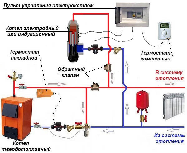
Piping of an electric and TT boiler with two pumping devices
In the scheme with a buffer tank, it is necessary to install an additional pump, because at least 2 circulation circuits are involved in it - boiler and heating.
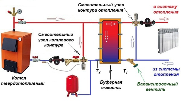
Buffer capacity divides the system into 2 circuits, although in practice there are more
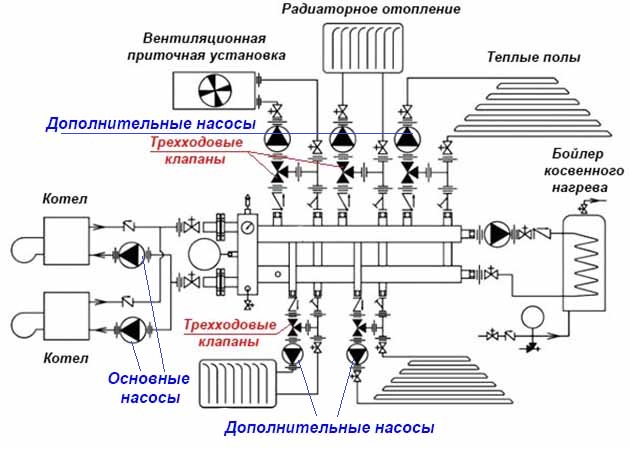
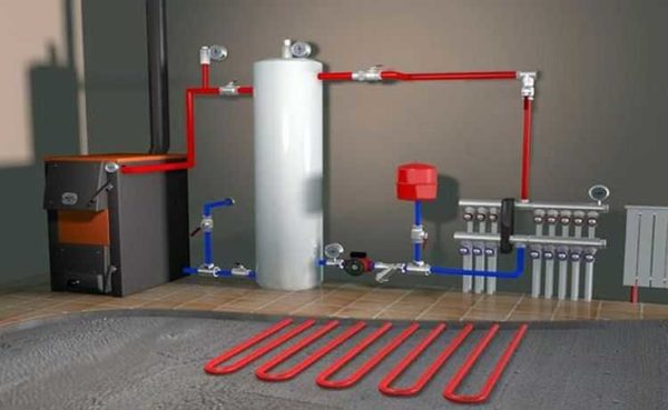
A separate story is a complex heating scheme with several branches, implemented in large cottages on 2-4 floors. Here, from 3 to 8 pumping devices (sometimes more) can be used, supplying the coolant floor by floor and to different heating devices. An example of such a circuit is shown below.
Finally, the second circulation pump is installed when the house is heated with water-heated floors. Together with the mixing unit, it performs the task of preparing a heat carrier with a temperature of 35–45 °C. The principle of operation of the circuit below is described in this material.
This pumping unit makes the coolant circulate through the heating circuits of underfloor heating
Reminder. Sometimes pumping devices do not need to be installed for heating at all. The fact is that most electric and gas wall-mounted heat generators are equipped with their own pumping units built into the housing.
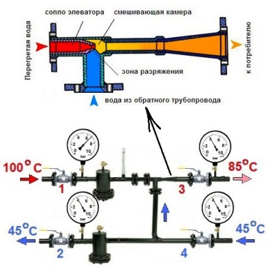
Dependent open heating system
The main feature of the dependent system is that the coolant flowing through the main networks directly enters the house. It is called open because a coolant is taken from the supply pipeline to provide the house with hot water. Most often, such a scheme is used when connecting multi-apartment residential buildings, administrative and other public buildings to heating networks. The operation of the scheme of the dependent heating system is shown in the figure:
When the temperature of the coolant in the supply pipe is up to 95 ºС, it can be directed directly to the heating devices. If the temperature is higher and reaches 105 ºС, then a mixing elevator unit is installed at the entrance to the house, whose task is to mix the water coming from the radiators into the hot coolant in order to lower its temperature.
The scheme was very popular during the Soviet era, when few people cared about energy consumption. The fact is that a dependent connection with elevator mixing units works quite reliably and practically does not require supervision, and installation work and material costs are quite cheap. Again, there is no need to lay additional pipes to supply hot water to houses when it can be successfully taken from the heating main.
But this is where the positive aspects of the dependent scheme end. And there are many more negative ones:
- dirt, scale and rust from the main pipelines safely enters all consumer batteries. Old cast-iron radiators and steel convectors didn’t care about such trifles, but modern aluminum and other heating appliances definitely didn’t care;
- due to a decrease in water intake, repair work and other reasons, a pressure drop often occurs in a dependent heating system, and even water hammer. This threatens with consequences for modern batteries and polymer pipelines;
- the quality of the coolant leaves much to be desired, but it goes directly to the water supply. And, although the water in the boiler room goes through all the stages of purification and desalination, kilometers of old rusty highways make themselves felt;
- it is not easy to regulate the temperature in the rooms. Even full bore thermostatic valves quickly fail due to the poor quality of the coolant.
Advantages of independent systems
Already at the approach to the main consumers of the home water supply network, a whole range of preparatory measures is provided to ensure the distribution, filtration and adjustment of the coolant pressure. All loads fall not on the final equipment, but on the heat exchanger with a hydraulic tank, which directly receive resources from the main source. Such resource preparation is practically impossible in private when operating dependent heating systems. The connection of an independent circuit also allows rational use of water for drinking needs of optimal purification. The streams are divided according to the intended purpose and each line can provide a separate level of training that meets the technological requirements.
Cons of dependent heating systems
Of the negative aspects of the operation of such systems, the following are noted:
- Intensive contamination of working circuits with scale, dirt, rust and all kinds of impurities that may well enter consumer equipment.
- Higher requirements for repair activities. The fact is that dependent and independent heating systems in such cases require the connection of specialists of different levels. It is one thing to make repairs on the main line once a year, and another thing is to monthly perform a comprehensive inspection of the elevator assembly piping at home.
- Water hammer is possible. Incorrect connection of communications or excessively high pressure in the circuit can lead to rupture of pipes.
- Low basic quality of the coolant in terms of composition.
- Difficulties of control and management. At technological stations for municipal water heating, the process of updating the same shut-off valves is rather slow, which can lead to disturbances in pressure balances.
Helpful Hints
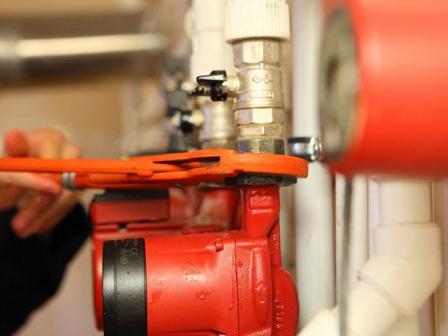
To exclude an arbitrary change in the flow of water, shutoff valves are attached to the inlet-outlet area of the circulation pump. The connecting nodes must be treated with a "sealant", one hundred will increase the performance of the entire heating system.
In order to quickly and correctly install the pump pump, you need selected connections and threads. To reduce the time it takes to search for all the necessary parts, look in plumbing stores for a special device with already selected fasteners. After the installation process of the pumping unit is completed, the system is filled with water or other coolant.
Before you start the system, you should open the central valve to remove air pockets - the water that appears will notify you of the complete removal of air from the system.
About quantity and breakdowns
The number of circulation pumps required to heat a private house can be determined based on the entire length of the pipeline. If its length is about 80 m, then one is enough. If this length is exceeded, consider increasing the number of pumps in the system.
The reasons for the failure of circulation pumps can be incorrect installation, arbitrary location of the cable connection and terminal module, as well as non-compliance with the rules for operating the heating boiler
To avoid malfunctions, it is important not to ignore the procedures for regular air release and take care of a good cleaning of the system from mechanical particles.
But it should be remembered that all breakdowns of the circulation pump must be corrected by specialists. Therefore, if malfunctions have already appeared and are detected, it is best to contact the repair service.
6 Operating modes of the oil pipeline when individual oil pumping stations are turned off. Construction of combined characteristics.
Temporary
shutdown of any pumping
stations can be caused by interruptions
in the power supply system, an accident,
repair work, etc. When leaving
out of order pumping station mode
pipeline will change dramatically. Consider
oil pipeline, consisting of one
operating area with n
transfer stations. All PS
equipped with the same type of pumps.
Let's write the pressure balance equation
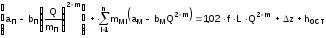 ,
,
(1.70)
where aP,
bP,
aM,
bM
– pressure characteristic coefficients
booster and main pump;
mM
i
– number of operating trunk lines
pumps at the i-th pumping station;
mP
– number of operating booster pumps
on the GPS.
From
head balance equation performance
oil pipeline with all working
stations is
. (1.71)
If
would the oil pipeline be designed to work
at any head (pressure), then at
shutdown of any one station
in the pipeline would be
. (1.72)
Obviously,
what Q*
V
the reality of the magnitude of the pressure and
supports of pumping stations should
satisfy the conditions
, (1.73)
where HPS
max i,
Hmin
i
– permitted head and back pressure values
i-th PS.
V
As an example, consider the work
oil pipeline with four pumping stations
stations. Let us assume for simplicity that
all pumping stations are equipped with
single-type pumps, oil pipeline
consists of one operational
section, crossing points along the highway
no oil pipelines (L=LR),
restrictions on pressure and backwater of substation
are the same (HPSmax,
Hmin).
Consider
case when emergency shutdown
occurred at station PS-4 (Fig. 1.26).
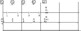
Rice.
1.26. Design scheme of the oil pipeline
pumping
station located before disconnected
(PS-3), will work on dual
haul, that is, the length of the third
linear section will be equal to l3-4=l3+l4.
Let's check
fulfillment of the boundary conditions (1.73).
We present the results of calculations in
tabular form (Table 1.6).
table
1.6
Estimated
values of backwaters and pressures of PS
|
Plot |
Backwater |
pressure |
pressure |
Losses |
|
1 |
HCT1=mM1(aM––bMQ*2-m) |
HPS1=H1+ |
H1=1.02fl1Q*2-m+z2-z1 |
|
|
2 |
H2= |
HCT2=mM2(aM––bMQ*2-m) |
HPS2=H2+ |
H2=1.02fl2Q*2-m+z3-z2 |
|
3+4 |
H3= |
HCT3=mM3(aM––bMQ*2-m) |
HPS3=H1+ |
H3-4=1.02f(l3+l4)Q*2-m+ +zK-z3 |
|
KP |
HKP= |
Graphic
solving the problem of regulating work
oil pipeline when one of the
pumping stations shown in
rice. 1.27.
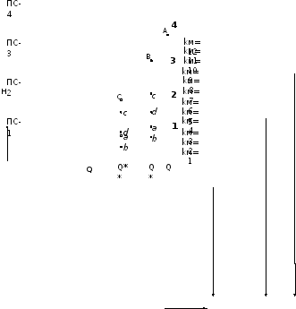
Rice.
1.27. The combined characteristic of PS and
pipeline sections
Conditional
designations :
1
- characteristics of the site 1.02.f.l1.Q2-m
+
z1 ,
(z1=
z2-z1);
2
- site characteristic 1.02.f.(l1+l2).Q2-m
+
z2
, (z2=
z3-z1);
3
- site characteristic 1.02.f.(l1+l2+l3).Q2-m
+
z3
, (z3=
z4-z1);
4
- site characteristics
1.02.f.(l1+l2+l3+l4).Q2-m
+
z4+
host
, (z4=
zTO-zH);
a-b
, a'-b' - backwater at PS-2; c-d, c'-d' - backwater
at PS-3;
kM
– total number of operating trunk lines
pumps
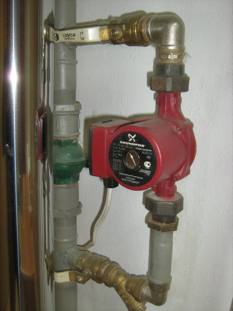
Where to put
It is recommended to install a circulation pump after the boiler, before the first branch, but it does not matter on the supply or return pipeline. Modern units are made from materials that normally tolerate temperatures up to 100-115 ° C.There are few heating systems that work with a hotter coolant, therefore considerations of a more “comfortable” temperature are untenable, but if you are so calmer, put it in the return line.
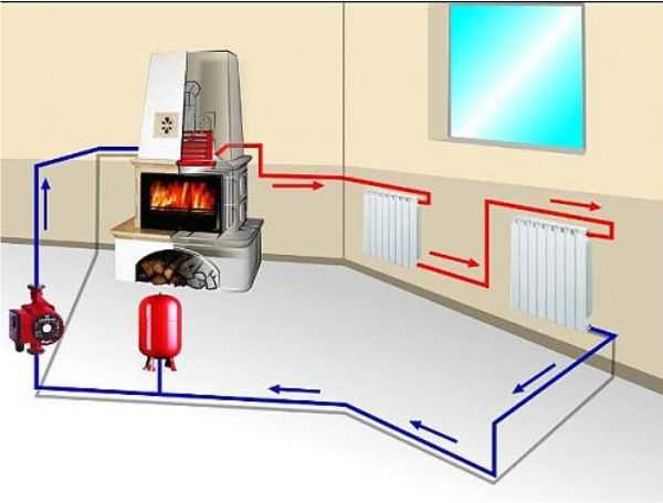
Can be installed in the return or direct pipeline after/before the boiler up to the first branch
There is no difference in hydraulics - the boiler, and the rest of the system, it does not matter whether there is a pump in the supply or return branch. What matters is the correct installation, in the sense of tying, and the correct orientation of the rotor in space
Nothing else matters
There is one important point at the installation site. If there are two separate branches in the heating system - on the right and left wings of the house or on the first and second floors - it makes sense to put a separate unit on each, and not one common one - directly after the boiler. Moreover, the same rule is preserved on these branches: immediately after the boiler, before the first branch in this heating circuit. This will make it possible to set the required thermal regime in each of the parts of the house independently of the other, as well as save on heating in two-story houses. How? Due to the fact that the second floor is usually much warmer than the first floor and much less heat is required there. If there are two pumps in the branch that goes up, the speed of the coolant is set much less, and this allows you to burn less fuel, and without compromising the comfort of living.
There are two types of heating systems - with forced and natural circulation. Systems with forced circulation cannot work without a pump, with natural circulation they work, but in this mode they have a lower heat transfer. However, less heat is still much better than no heat at all, so in areas where electricity is often cut off, the system is designed as hydraulic (with natural circulation), and then a pump is slammed into it. This gives high efficiency and reliability of heating. It is clear that the installation of a circulation pump in these systems has differences.
All heating systems with underfloor heating are forced - without a pump, the coolant will not pass through such large circuits
forced circulation
Since a forced circulation heating system is inoperative without a pump, it is installed directly into the gap in the supply or return pipe (of your choice).
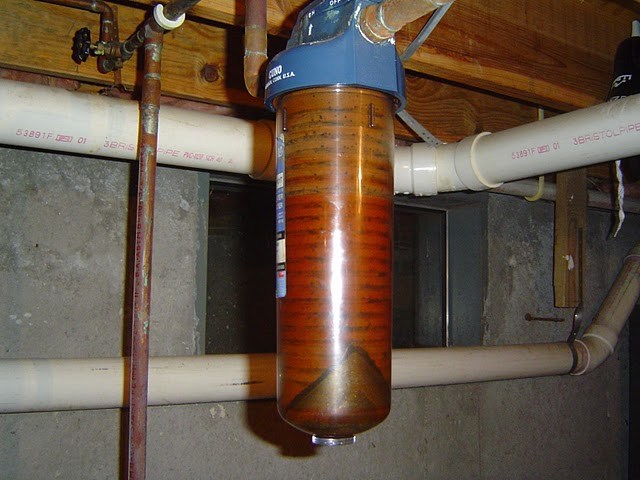
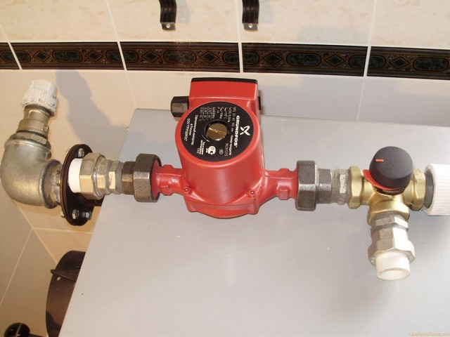
Most problems with the circulation pump arise due to the presence of mechanical impurities (sand, other abrasive particles) in the coolant. They are able to jam the impeller and stop the motor. Therefore, a strainer must be placed in front of the unit.
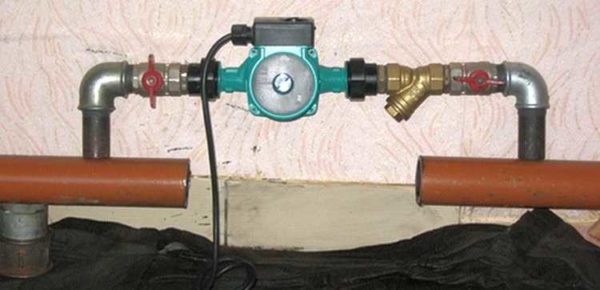
Installing a circulation pump in a forced circulation system
It is also desirable to install ball valves on both sides. They will make it possible to replace or repair the device without draining the coolant from the system. Turn off the taps, remove the unit. Only that part of the water that was directly in this piece of the system is drained.
natural circulation
The piping of the circulation pump in gravity systems has one significant difference - a bypass is required. This is a jumper that makes the system operational when the pump is not running. One ball shut-off valve is installed on the bypass, which is closed all the time while pumping is in operation. In this mode, the system works as a forced one.
Scheme of installation of a circulation pump in a system with natural circulation
When electricity fails or the unit fails, the faucet on the jumper is opened, the faucet leading to the pump is closed, the system works like a gravitational one.
Mounting Features
There is one important point, without which the installation of the circulation pump will require alteration: it is required to turn the rotor so that it is directed horizontally. The second point is the direction of the flow.There is an arrow on the body indicating in which direction the coolant should flow. So turn the unit around so that the direction of movement of the coolant is “in the direction of the arrow”.
The pump itself can be installed both horizontally and vertically, only when choosing a model, see that it can work in both positions. And one more thing: with a vertical arrangement, the power (created pressure) drops by about 30%. This must be taken into account when choosing a model.
Circulation pump insert
If the pump was not previously included in the heating system. its "tie-in" into the pipeline is required. Since this operation requires the performer to have some skills and the availability of special equipment, it can be entrusted to professionals, or you can do the work yourself, having previously familiarized yourself with the pipeline installation technology. The order of work and the list of equipment used will depend on the chosen tie-in method and pipeline material.
There are 2 ways to tie in a circulation pump:
- on the main section of the pipeline;
- on the bypass section (bypass).
Installing the unit on the main site involves less time and money, but has one significant drawback. The pump is powered by the mains, so with this installation method, during a power outage in an apartment or house, the heating will not be able to function.
The second method is more complicated, but provides the heating system with an increased level of autonomy. In this case, when the system is operating in normal mode, the coolant moves through the bypass channel, and the corresponding section of the main line is closed using a specially installed ball valve. During a power outage, the valve opens and the liquid moves through the pipeline in a natural way.
Scheme of installation of the pump on the bypass channel (bypass).
This option, although common, has one big drawback - a tap on the main line. It is better if a ball valve is installed instead of a tap.
Installation of a pump on the supply of a gas floor boiler in a heating system with natural circulation. An article on the topic "How to choose a gas boiler" may be useful to you.
In normal operation, the valve is closed by the overpressure generated by the pump above the ball. If the pump is de-energized, the ball rises under the pressure of water moving naturally along the highway. This option is relevant if the installation of the pump for one reason or another is carried out on the "supply".
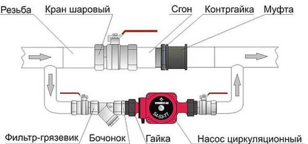
Pump tie-in mounting kit includes:
- pipes of the required diameter;
- elements of pipeline fittings;
- union nuts (for polypropylene pipelines) or shackles (for steel pipes);
- mud filter;
- stopcocks;
- check valve.
The diameter of the tie-in pipes must correspond to the diameter of the already installed pipeline, and their total length is determined by the results of measurements at the site of the proposed installation of the pump. In the same way, a set of pipeline fittings is selected. Union nuts (or spurs) are used for quick installation and removal of the pump.
The dirt filter is installed directly before the entrance to the unit. It is necessary to protect the pump from the ingress of contaminants, the source of which may be deposits on the inner surface of the pipelines. The drain hole of the filter must point downwards to allow periodic cleaning.
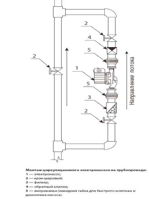
Shut-off valves are placed at the inlet to the pump in front of the filter and at the outlet of it, so that, if necessary, the unit can be dismantled without stopping the entire system. When installing the supercharger on the bypass section, an additional valve is installed on the main line parallel to the pump. The check valve is designed to protect the system from hydraulic shocks.It is mounted at the outlet of the pump in front of the stopcock.
Pump installation
After the pipeline section is fully prepared, you can proceed directly to the installation of the unit itself. The rotor supports of the pumps used in heating systems are not designed for operation in the vertical position of the unit, therefore only its horizontal arrangement is allowed.
Installation of the pump with the wrong arrangement of the axis of the rotor.
The delivery set of the circulation pump includes the unit itself with a built-in or external power supply, sealing gaskets, a passport for the product and instructions for installation and operation. Before starting the installation, it is necessary to familiarize yourself with the contents of the instructions in order to take into account all the features of the installation process and connection of a particular model. Some pumps are not supplied with seals and must be purchased separately.
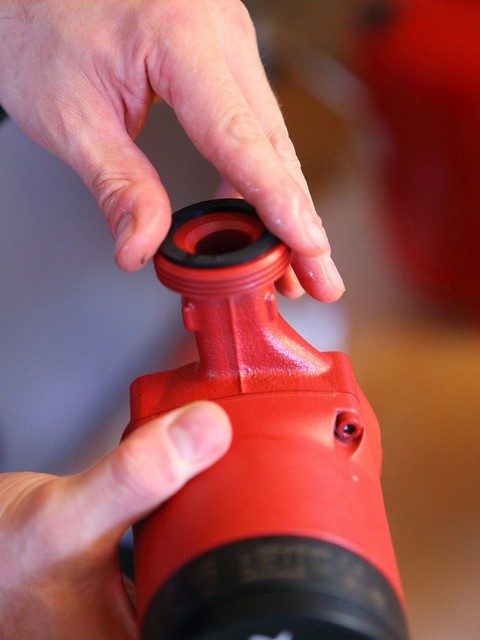
Installation of a sealing gasket.
If the pump is mounted on a vertical section of the pipeline, then its lower flange is placed on the mating flange of the pipeline, on which a sealing gasket is placed, after which the connection is screwed with a union nut. Next, the seal is placed on the upper flange of the pump, and the connection is screwed with a second nut. The nuts are then tightened with a wrench. In some cases, the threaded connections of the pump with the pipeline are additionally sealed with a sealing tape. When mounting on a horizontal section, any sequence of flange connections is allowed.
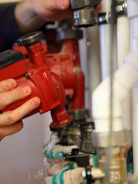
Installation of a circulation pump.
Then it is necessary to open the taps on both sides of the unit so that the internal cavities of the pump are filled with liquid. If the design of the supercharger does not provide for an automatic air release valve, it is bled using a special screw that opens the bypass hole.
Tightening the union nut.
After installing the pump in the pipeline, it is necessary to connect it to the power supply network. The socket for the power supply of the unit must be grounded. If the pump provides for the possibility of multi-mode operation, switch the lever to the desired mode. The heating circulation pump connected to the power supply starts to perform forced pumping of the coolant, providing more intensive heat exchange and fuel economy of the boiler by reducing the temperature difference between the coolant in the supply and return lines.
Interior solution: decorative grilles for heating radiators
Optimal thermal insulation for heating pipes
Independent insulation of heating pipes on the street
Is it possible to convert one system to another
Theoretically, this is quite possible - both in one direction and in the other. Basically, they just modernize dependent systems, but there may well be a need to reconstruct independent infrastructure. At the same time, the most rational option, when it will be possible to preserve the advantages of both systems to varying degrees, will be the implementation of an independent heating system with closed input circuits. This means that those functions that in a standard independent circuit were performed by a separate collector unit with a full set of control units, in this case, will be taken over by point-mounted devices. At different levels of the home network, before approaching consumers, it is possible to insert filters, compressor units, distributors, circulation pumps and a hydraulic tank.
Classification
Aggregates are of two types. The first type is "dry" pumps. In equipment of this type, the coolant and the rotor do not interact with each other. The working part of the rotor is isolated and separated from the engine by stainless steel sealing rings.When starting, the rings move, a thin film of water seals the connections due to different pressures in the system and in the environment.
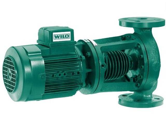
The efficiency of a "dry" unit is about 80%. This equipment is very sensitive to contamination of the water in the system, and if small particles enter, it quickly fails. The dry type pump is quite noisy, so when installing it, you should take care of the soundproofing of the room.
"Wet" pumps differ in their design from "dry" ones. Its impeller is located directly in the coolant. The stator and the moving part of the mechanism are separated by a special glass that provides waterproofing of the engine. "Wet" units are cheaper to operate and repair, they are quieter than "dry" ones.
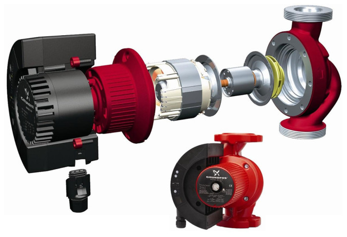
The disadvantages of "wet" type equipment include their low efficiency - only about 50%. This is due to the low sealing of the sleeve separating the stator and coolant. Although even such a performance is quite enough for heating any private house.