We calculate the required volume of the accumulator for the water supply system
The volume of the accumulator depends on the number of points of consumption (shower, sink, toilet), as well as on the number of residents (a secondary indicator). It is worth considering the power (type) of the pump.
| Pump | Power, W | Location | Hydraulic accumulator tank volume, l | |
|---|---|---|---|---|
| A type | Surface | ≤ 1000 | Horizontal | 24 |
| ≥1000 | Horizontal | 50 | ||
| Submersible | ≤500 | Horizontal or vertical | 24 | |
| 500-1000 | Horizontal or vertical | 50 | ||
| 1000-1500 | Horizontal or vertical | 100 |
 Horizontal tanks are less reliable than vertical ones.
| Number of water intake points | Pump capacity, m3/h | Hydraulic accumulator tank volume, l |
|---|---|---|
| ≤3 | 2 | 24 |
| 3-8 | 3,5 | 50 |
| ≥8 | 5 | 100 |
The cost of various models of hydraulic tanks in the Russian market
You can buy a hydraulic accumulator for water supply systems in large construction hypermarkets, specialized stores or on Internet resources. When choosing a tank, it is better to immediately purchase a volume with a margin. Of course, later you can buy another one and connect it with the first one in parallel (this is allowed), but the price of a hydraulic accumulator for water supply systems of 100 liters will be lower than the cost of two containers of 50 each. Consider some models of such devices with their technical characteristics and prices, as of January 2018.
 Hydraulic accumulator "Belamos 100 VT" for 100 liters. This is enough for a family of 4
If we take average values, then the price of a hydraulic accumulator for water supply systems of 50 liters (the most common) is not so high. This means that the acquisition of this necessary device in the family budget will not make a big hole.
 The Wester WAO flange is bolted with nuts
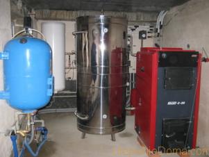
Heat accumulator device
The battery tank in the heating system is a high tank in the form of a cylinder, or a square, a rectangle, equipped with nozzles (4 - 20 pieces). For connection to the boiler - lower inputs, and for connection to the heating system - upper ones.
The volume of liquid inside the device varies from 200 to 3000 cubic meters (for a house with an area of 150 square meters, a capacity of at least 1000 cubic meters is needed).
Thermally insulated water buffer tanks exclude heat loss and also exclude overheating of the air inside the room where they are installed (thermal radiation of the tank without insulation reaches up to 2 cubic meters).
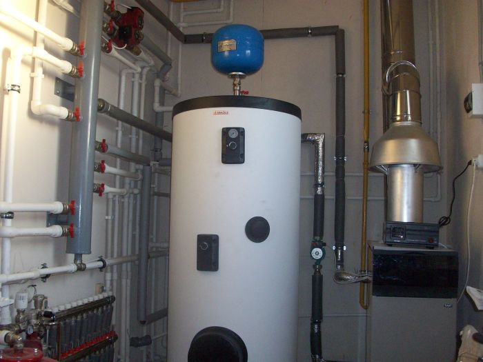
The heat accumulator for a solid fuel boiler with a heat exchanger consists of the following elements:
- liquid tank,
- heat exchanger device at the bottom of the tank,
- electric heaters,
- magnesium anode,
- layer heating apparatus.
Instead of one source and consumer of heat, several devices can be connected to it through different nozzles.
Different models are used in everyday life: a thermal accumulator without a heat exchanger, a heat accumulator for a heating system with a tank built into the design and models, and models equipped with a heat exchanger built into the tank for hot water supply.
You can make a heat accumulator for heating with your own hands, but the efficiency of the device is much less, it will take up a large area. The cost of a homemade unit is lower, but the safety of the circuit will suffer.
Wiring diagram
After the tank is in place, it must be properly connected to the piping network. The most popular is the standard heat accumulator connection diagram shown in the figure:
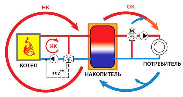
To implement it, you will need 2 circulation pumps and the same number of three-way valves. Pumps provide circulation in separate circuits, and valves provide the required temperature. In the boiler circuit, it should not fall below 55 ºС in order to avoid the appearance of condensate in the solid fuel boiler, this is what the valve on the left side of the diagram does.
The heat carrier in the heating pipelines is heated depending on the need for heat, and therefore the connection of the heat accumulator on the other side is also carried out through the mixing unit. The valve can control the water temperature in automatic mode, focusing on the sensor or using a thermostat. To connect the tank to an electric boiler that is not afraid of condensate, you can use the simpler scheme shown in the video:
Do-it-yourself installation steps for a hydroaccumulator for water supply systems
Work on the installation of the purchased accumulator is carried out in several stages. The first thing to do is check the pressure in the air chamber. This is done simply, using a car pump or compressor equipped with a pressure gauge. The pressure is made slightly greater than the rate at which the pump turns on. The upper level is set from the relay and is set one atmosphere above the primary level.
Next, you should decide on the installation scheme.
 A simple hydraulic tank connection diagram for a water supply system
Choosing a hydraulic tank connection scheme
The most convenient is the connection diagram of a hydraulic accumulator with a five-pin collector. Installation is carried out according to the scheme, which is in the technical documentation. A collector with five outlets is screwed to the fitting of the accumulator. The remaining 4 outputs from the collector are occupied by a pipe from the pump, water supply to the dwelling, a control relay and a pressure gauge. If it is not planned to install a measuring device, then the fifth output is muted.
Connecting the accumulator to the water supply system
After assembling all the nodes, the pump (if the system is equipped with a submersible pump) or the hose (if the pump is surface) is first lowered into the well or well. The pump is powered. That, in fact, is all.
 FUM-tape is mandatory for use when installing connections
Important! All connections are made with winding FUM tape or flax. It should be understood that the pressure in the system will be quite high
However, you should not be too zealous either, everything is good in moderation. Otherwise, there is a risk of breaking the nuts on the fittings.
Having dealt with the installation, you can move on to the issue of replacing the membrane, which often fails in models with a vertical arrangement. Here we will make a step-by-step instruction with photo examples.
| Photo example | Action to take |
|---|---|
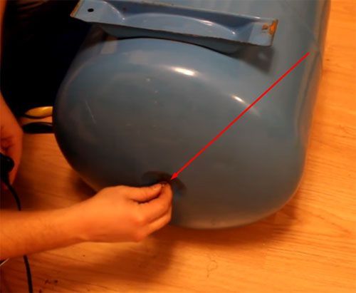
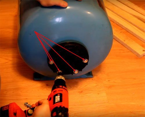 |
First, we unscrew the bolts of the flange of the dismantled hydraulic tank. They are wrapped "in the body" or tightened with nuts - depending on the model. |
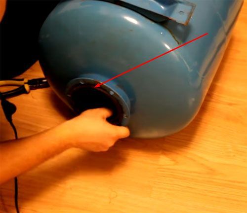
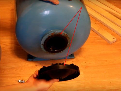 |
When the bolts are out, the flange can be easily removed. Let's put it aside for now - to pull out the failed pear, you need to unscrew one more nut. |
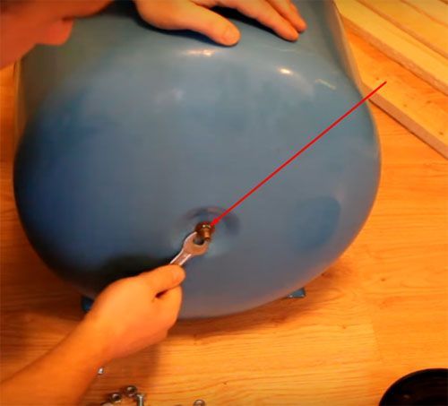 |
Expand the container. At the back is a purge nipple. The nut also needs to be removed. There may be two of them, one of which acts as a locknut. This is done with a key of 12. |
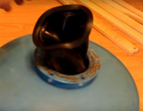 |
Now, with a little effort, the pear is pulled out through the large hole on the side of the flange. |
 |
We lay out a new pear, we expel air from it. This is necessary to make it more convenient to install it in the tank. |
 |
Having folded four times in length, we put it into the container completely, including the part that was outside during dismantling. This is done so that it is possible to get the nipple into the hole intended for it. |
 |
The next stage is not for people with a full physique. Experienced craftsmen say that in order to install the nipple for the accumulator in place, sometimes you have to call your wife for help - they say, her hand is thinner. |
 |
Once in the hole, it is imperative to make a nut so that during further assembly it does not go back. In this case, you will have to start all over again. |
 |
We straighten the pear seat and tighten the nuts on the nipple. The matter remains small ... |
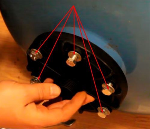 |
... - put the flange in place and tighten the bolts. When tightening, do not be zealous over one screw.Having slightly tightened everything, we begin broaching through the system of opposite units. This means with six bolts the order is as follows - 1,4,2,5,3,6. This method is used in tire shops when pulling wheels. |
Now it is worthwhile to deal with the necessary pressure in more detail.
What pressure should be in the accumulator: we check the system for operability
The factory settings of the hydraulic tanks imply a set pressure of 1.5 atm. It does not depend on the volume of the tank. In other words, the air pressure in a 50-liter accumulator will be the same as in a 150-liter tank. If the factory settings are not suitable, you can reset the indicators to values \u200b\u200bthat are convenient for the home master.
Very important! Do not overestimate the pressure in the accumulators (24 liters, 50 or 100 - it doesn’t matter). This is fraught with failure of faucets, household appliances, pump
1.5 atm., installed from the factory, are not taken from the ceiling. This parameter is calculated on the basis of numerous tests and experiments.
 With this pressure gauge it is quite easy to measure the air pressure in the tank
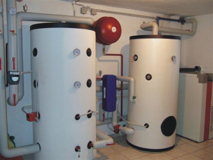
Advantages and disadvantages of TA
TA dimensions are impressive
Let's start with the benefits of using a hot water and heating storage tank:
- temperature stability in the circuit;
- fuel economy;
- reduction in the number of fuel loadings into the boiler;
- the heater fully realizes its power potential;
- the possibility of saving if an electric boiler acts as a heater;
- simultaneous heating of the heat carrier in the heating circuit and hot water.
There is nothing that does not have its shortcomings. Same with heat sinks.
- take up a lot of space;
- are expensive;
- need a more powerful boiler.
Everyone understands that every business must be done well and efficiently, preferably adhering to all the rules. In practice, unfortunately, this is not always possible. Here you need to count the money, because everything always rests on them. The use of buffer tanks really helps to reduce fuel costs and stabilize the temperature in the circuit. At the same time, initially you will need to buy a boiler twice as powerful, which, of course, is more expensive, and buy the heat accumulator itself, which is also not cheap. You can make purchases gradually, first make a circuit without a storage tank, and then buy it over time if the desire does not disappear. In this case, it will be necessary to slightly correct the layout of the heating pipes.
Interesting on the topic:
- Replacement of heating pipes
- Which heater to choose
- The use of boxes in the heating system
- Features of heating industrial premises
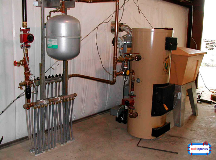
Principle of operation and design
The main task of the heat accumulator is to accumulate additional heat in its capacity and, in case the boiler cannot release energy, perform this function for it. The operation of such a device can reduce the level of energy consumption by several percent if it is installed in an electric boiler, and this, in turn, reduces the cash costs of the owner of the house for electricity.
This equipment, embedded in a solid fuel boiler, works as follows: in the absence of a source of thermal energy in the boiler, it stops its work, and, accordingly, the water in the main pipelines gradually begins to cool. It is water that squeezes the hot coolant out of the battery tank into the system, which makes its operation uninterrupted.
Design
In fact, the heat accumulator used to connect to the heating system has a simple design: a tank with thermally insulated walls and several pipes needed to connect to the boiler.
When choosing equipment, you should carefully calculate the required level of thermal insulation of its walls - it is best to play it safe and purchase a container with thick walls.
As a rule, the volume of a heat accumulator for a solid fuel boiler is calculated based on the ratio that 1 kW of boiler power should account for 25 liters of tank volume.
Applications
Experts recommend inserting a heat accumulator into the heating system at home in the following cases:
- high daily demand for hot water;
- if a solid fuel boiler is used (the amount of fuel used is reduced);
- if there is an electric boiler in the house, and at night the tariffs for electricity consumption are not reduced.
How quickly energy reserves are used up
The accumulative tank for the heating system, included in the circuit, heats the premises when the boiler is turned off, it is not necessary to heat the boiler constantly, while saving fuel up to 30 - 50%.
The backup heat consumption time depends on the following factors.
- Capacity tank sizes.
- Temperatures of the air space inside and outside the room.
- Heat loss.
- "Smart" automation.
- Consumption expense.
Heating with the boiler turned off lasts several hours, or two to three days.
Connecting a heat accumulator to a solid fuel boiler does not allow thermal energy to “fly into the pipe”. Heat accumulates inside the tank. With automation equipment, the heat supply is economically spent on heating radiators, underfloor heating, and water supply.
If there is a preferential night tariff for electricity, the battery is charged at night.
In order to make a boiler room in the house on your own, you need to think through a lot of details.
1000 l. thermal energy is enough for 11 - 12 daytime hours for a room of 150 square meters. m. This is an effective economical backup heat supply with a difference in tariffs.
Hydraulic accumulator connection diagram
Depending on the assigned functions, the scheme for connecting the accumulator to the plumbing system may be different. The most popular hydraulic accumulator connection diagrams are shown below.
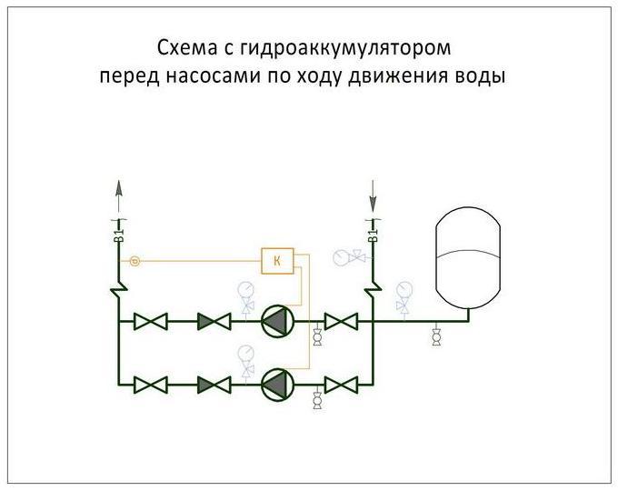
Booster pumping station piping scheme
Such pumping stations are installed where there is a large water consumption. As a rule, one of the pumps at such stations operates constantly. At the booster pumping station, the accumulator serves to reduce pressure surges during the activation of additional pumps and to compensate for small water intakes.
Such a scheme is also widely used when there is a frequent interruption in the supply of electricity to booster pumps in the water supply system, and the presence of water is vital. Then the supply of water in the accumulator saves the situation, playing the role of a backup source for this period.
The larger and more powerful the pumping station, and the more pressure it must maintain, the larger the volume of the hydraulic accumulator, which acts as a damper, should be. The buffer capacity of the hydraulic tank also depends on the volume of the required water supply, and on the difference in pressure when the pump is turned on and off.
Scheme for a submersible pump
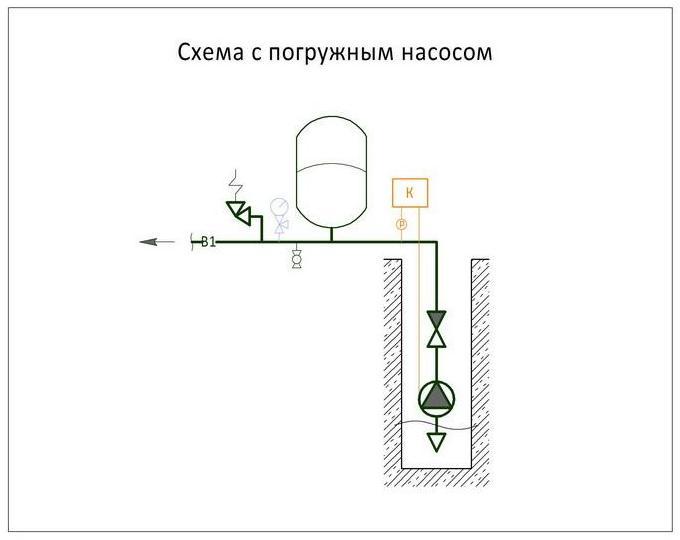
For long and uninterrupted operation, a submersible pump must make from 5 to 20 starts per hour, which is indicated in its technical specifications.
When the pressure in the water supply system drops to the minimum value, the pressure switch automatically turns on, and at the maximum value it turns off. Even the smallest water flow, especially in small water supply systems, can lower the pressure to a minimum, which will instantly give a command to turn on the pump, because water leakage is compensated by the pump instantly, and after a few seconds, when the water supply is replenished, the relay will turn off the pump. Thus, with minimal water consumption, the pump will run almost idle. This mode of operation adversely affects the operation of the pump and can quickly disable it.The situation can be corrected by a hydraulic accumulator, which always has the necessary supply of water and successfully compensates for its insignificant consumption, and also protects the pump from frequent switching on.
In addition, a hydraulic accumulator connected to the circuit smooths out a sharp increase in pressure in the system when the submersible pump is turned on.
The volume of the hydraulic tank is selected depending on the frequency of switching on and the power of the pump, the water flow per hour and the height of its installation.
Connecting the accumulator to the water heater
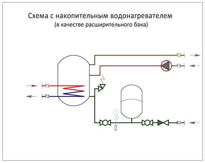
For a storage water heater in the connection diagram, the accumulator plays the role of an expansion tank. When heated, the water expands, increasing the volume in the water supply system, and since it does not have the ability to compress, the most minimal increase in volume in a confined space increases pressure and can lead to the destruction of the elements of the water heater. Here, too, a hydraulic tank will come to the rescue. Its volume will directly depend and increase from an increase in the volume of water in the water heater, an increase in the temperature of the heated water and an increase in the maximum allowable pressure in the water supply system.
Connecting the accumulator to the pumping station
The hydraulic accumulator is connected in front of the booster pump along the water course. It is needed to protect against a sharp decrease in pressure in the water supply network at the moment the pump is turned on.
The capacity of the accumulator for the pumping station will be the greater, the more water is used in the water supply system and the smaller the difference between the upper and lower pressure scales in the water supply system in front of the pump.
Types of membrane tanks and their features
There are vertical and horizontal hydraulic tanks, which are mounted in different ways at the installation site. There is another important point. A small amount of air may accumulate in the part of the hydraulic tank that contains water over time. This air should be periodically removed so that air plugs that are quite dangerous for it do not get into the system. In vertical containers, air accumulates at the top and a special nipple is used to remove it.
With horizontal hydraulic tanks, everything is somewhat more complicated. To bleed the accumulated air, you will need not only a nipple, but also a ball valve, as well as a sewer drain.
Owners of small hydraulic tanks, the capacity of which is less than 100 liters, need to get rid of excess air in a different way. For this you should:
- Turn off power.
- Open mixer valve.
- Wait until the tank is empty.
- Close the tap.
- Connect the system to the power supply so that the tank is filled again.
Excess air will come out with the water. This procedure should be done at least once a month.
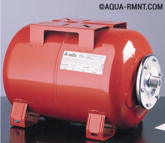
Red hydraulic tanks are designed for hot water supply systems. Although the membrane in them is made of fairly durable rubber, they should not be used to supply cold water.
Manufacturers offer red and blue hydraulic tanks, as well as colorless ones. The blue devices are designed for use in a cold water supply system. For the manufacture of the membrane in such tanks, food-grade rubber is used, which is safe for human health. Red hydraulic tanks are designed for heating and hot water systems. It is not recommended to use them for cold water, since the membrane in such tanks is made of a different rubber. In addition, the operating pressure threshold for blue hydraulic tanks is higher and reaches 8 Bar.
Usually water enters the accumulator from below, and on top, as already noted, there is a nipple through which air is removed. Therefore, each device has two threaded connections (usually inch or half inch), which should not be confused. An automatic air vent is often installed on the top nipple.
Sometimes there are situations when water is supplied to the hydraulic tank from above.It is believed that in this case automatic venting is not required. But you should take care of the filter so that particles of sand or other contaminants do not get into the system.