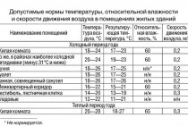
1 Determination of network water consumption
Estimated consumption
network water, t/h, in closed systems
heating supply to determine the diameters
pipes in water heating networks at
quality control of vacation
heats should be determined separately
for heating, ventilation and hot
water supply according to the formulas:
On the
heating
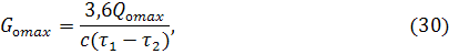
where
and
– supply and return temperatures
pipelines of the heat network at the calculated
outdoor temperature for
design of heating systems and
ventilation.
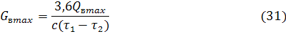
On the
ventilation
Estimated
hot water consumption
water supply, t/h
depend on the connection scheme
water heaters. With a two-stage
connection diagram water flow
determined by the following formulas:
where
hourly average
hot water consumption,
t/h
and
supply and return temperature
heat pipelines at the breakpoint of graphs
water temperatures.
Formulas
to determine the estimated flow
network water in a parallel circuit
heater connections are given
v .
Total
estimated consumption of network water, t/h,
in two-pipe heating networks with
quality regulation of heating
load:

where
coefficient,
taking into account the share of the average water flow
for hot water supply, accepted
depending on system power
heat supply (k=1.0
at k=1.0
at ).
For
consumers with a heat flow of 10 MW
and less total estimated consumption
water should be determined by the formula:

At
central quality regulation
heat release by combined load
heating and hot water supply
the estimated consumption of network water is determined
as the sum of water consumption for heating and
ventilation without taking into account the load of hot
water supply:

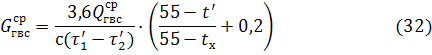
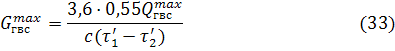
Estimated
network water consumption in non-heating
period, t/hdetermined
according to the formula:

where
define
according to formula (33), taking into account the fact that
maximum heat load
hot water supply
taking into account the increase in the temperature of the cold
water up to 15oC;
coefficient,
taking into account the change in water consumption by
hot water supply in non-heating
period in relation to heating,
accepted for housing and communal
sectors equal to 0.8. For resort and southern
cities,
for industrial enterprises.
EXAMPLE
4. For two
quarters of the district of the city to determine
estimated total network consumption
water. Data on calculated thermal
flows from example 1. Temperature
water in the supply pipe,
in the opposite
Heat supply is controlled
by combined heating load
and hot water supply.
Solution:
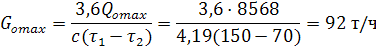
Estimated
consumption of network water for heating for
quarter No. 1 we find by the formula (30):
By
formula (31) for quarter No. 1 we find
estimated water consumption for ventilation:
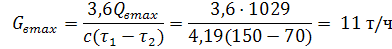
Note.
Estimated heat fluxes are taken taking into account
5% heat loss to the environment.
Total
the estimated flow of network water we calculate
by formula (36):

Similar
we will make calculations for quarter No. 2,
and put the results in table 4:
table
4 - Estimated consumption of network water for
two city blocks
|
quarter number |
|||
|
1 |
92 |
11 |
103 |
|
2 |
153 |
18 |
171 |
|
Total: |
274 |
Head of VET
____________
N.I. Chapurin
Boss
chemical shops
____________
I.A. Abramova
This instruction
is intended for the personnel of the chemical shop when they perform operations on
operation of a water treatment plant for feeding the heating network (clarification
on mechanical filters, single-stage Na-cationization).
The instructions include:
- characteristic
installation equipment,
— modes of operation of various
its knots
- security measures,
- starting, stopping and
maintenance of equipment during normal operation and emergency
situations
—
conditions
efficient operation of the water treatment plant.
INSTRUCTIONS SHOULD KNOW:
—
Chief
chemical shop shifts;
—
apparatchiks
HVO 5 category;
- HVO apparatchiks
4 digits;
- head of the CHL;
—
CHL engineer.
In the text of the instructions adopted
the following abbreviations:
PTS - feeding of the heating network;
VPU - water treatment
installation;
HVO - chemical water treatment;
BUV - softened water tank;
BOBV - tank of desiliconized
water;
NObV - desilicon pump
water;
SW - softened water;
DKV - decarbonized
water;
BDKV - tank
decarbonized water;
NDKV - pump
decarbonized water;
VDR - upper
drainage distribution device;
NDRU - lower
drainage distribution device;
HOW - chemically purified water;
RU - distribution
device.
GENERALI am a PART
CHP-2 chemical water treatment serves
for the preparation of chemically purified water according to two technological schemes:
1. For additives in
boiler feed water.
2. To feed the heating system.
Water for feeding the heating system
prepared according to the scheme:
clarification of raw water on mechanical
filters - Na-cationization - collection of water in BUV No. 1,2 - with UV pumps in
deaerator for feeding the heating network of the turbine shop.
The source of water supply is
river Ob.
Raw water is supplied to
chemical water treatment with raw water pumps installed in the ash room
boiler shop.
Raw water control
produced by an automatic control valve depending on the water level in the
BUV or manually through the bypass valve C-1.
Soft water consumption
is regulated by the duty personnel of the turbine shop.
With a normal flow pattern
raw water for cold water treatment (for clarifiers - along the line D 377 mm after PSV:
to feed the heating network - after the condensers of turbines No. 3 or No. 4 according to
line D 500 mm) the raw water temperature should be:
- for brighteners
+30º С ± 3 º С (winter-summer);
- to feed the heating system up to
+ 40 ºС.
With an emergency scheme for supplying raw
water at the WLU PTS clarifiers from the line DN 377 mm after PSV (at
disconnection of the line DN 377 mm after PSV mm after turbine condensers No.
3.4) should not be lower than 15o and not higher than 40ºС. Water temperature
40ºС is limited by PTB (RD 34.03.201-97 p.3.7.35), used
at CWT, the strongly basic cation exchanger KU-2-8 is operable at t up to 120-130o (Kostrikin
page 21), lowering the temperature below 15o-20o reduces the effect
regeneration of the cation exchanger, and also worsens the process of water softening (Golubtsov
p.217). The best effect of cation exchanger regenerations is achieved at a temperature
35-40o.
Raw water temperature at
clarifiers supported by automatic water temperature controller
for PSV.
Raw water temperature at
feeding of the heating network is supported by the driver of turbines No. 3,4,5 by
changes in the position of the turbine control diaphragm, in the condenser of which
raw water is heated.
Water for preparation
chemically treated water for feeding heating networks, heated in the condenser
turbines No. 3 and 4 and is supplied through the raw water pipeline D=500mm.
Raw water pipelines (D=377mm
and D=500mm) and chemically treated water
(D=500 mm and D=273 mm) pass along the outer
flyover.
9. Calculation of the deaerator for feeding the heating system.
rice. 2.6. Calculation scheme of the vacuum deaerator.osignVD2.10. Calculation of the HDPE system.424dr4525dr5626dr6727dr7’T Fig. 2.7. Calculation scheme of the HDPE system.6T5TpsOUuplTdvut’etcTnot raisedTT7ohTToToo2.11. Determining the steam flow to the turbine and checking its power.3. Thermal calculation of HDPE and optimization of its characteristics on a computer.Initial data for IPA 4:
- heated water flow Gv=0.84102=85.7 kg/s;
- inlet water temperature tin 1\u003d 136 ° C;
- heating steam pressure Р=0.52 MPa;
- heating steam saturation temperature tn\u003d 153 ° C;
- temperature difference of the heater t=2 оС
- latent heat of vaporization r=2102 kJ/kg;
- average heat capacity of waterR=4.19 kJ/kg оС;
- internal pipe diameter dext=0.018 m;
- pipe thickness =0.001m;
- thermal conductivity of brassst=85 W/m K;
- distance between partitions H=1 m;
- water velocity c=2 m/s;
- price of a ton of standard fuel Chere.=60 $/tce;
- specific cost of the heater surface kF=220 $/m2;
- extraction heat value coefficients j+1=0.4 and j=0,267;
- number of hours of use of installed capacity hSpanish=6000 h;
- Boiler efficiency ka=0,92;
- Heat flow efficiency tp=0,98.
LtdPhysical properties of water at tvf.322Physical properties of the condensate film at tn.3222ooo2ntr4. Determination of heat value coefficients.Calculation of power change factors.The coefficients of the value of the heat of extractions are calculated by the formula:Analysis of technical solutions using CCT selections.
- Reducing the temperature difference in HPH 6 by 1 °C.
- Installation of superheated steam cooler.
- Installation of a drainage pump on HDPE 2.
- Extender installation.
- Increase in pressure losses in the selection pipeline to LPH 4 by 2 times.
Ltd
- Atinstallation of a drainage cooler at the HPH 6.
5. Calculation of technical and economic indicators.6. Choice of auxiliary equipment of the turbine plant.
- We select feed pumps for supplying feed water at the maximum power of the installation with a margin of 5%:
Monpv
- Condensate pumps are selected according to the maximum steam flow into the condenser with a margin:
bookTo
- We select drainage pumps without a reserve (reserve - cascade drain) of the KS-32-150 type (PND 6).
- We choose low pressure heaters of type PN-200-16-7 I in the amount of 4 pieces.
- High pressure heaters in the amount of three pieces of type PV-425-230-35-I.
- We select deaerators with a deaerator column of the DP-500M2 type and a deaerator tank of the BD-65-1 type.
Conclusion.o2Literature.
2
2.6. Main and auxiliary equipment of heating plants
Water,
supplied to the heating network for the needs
consumers, at the CHPP it is heated in
network heaters of turbine units,
in peak heaters and in peak
hot water boilers, which are
to the main heating equipment
CHP. To the auxiliary heating plant
equipment include: make-up
heating network installation, network pumps,
storage tanks, recirculating
hot water boiler pumps, etc.
Peak
hot water boilers (PVK) are designed
for installation in CHP plants to cover
peaks of heating loads. Peak
hot water boilers are usually installed
in separate rooms at large thermal power plants
or in the main building at small CHP plants.
The fuel of these boilers is more
part of oil or gas. In view of the small
usage during the year peak
boilers are simple in design
and inexpensive. The building can be carried out
only for the lower part of the boilers, the upper
some of them remain open.
air. Before the commissioning of CHPPs, water-heating
boilers can be used for temporary
district heating
district. Network water is heated
in series in network heaters
up to 110÷120С,
and then in PVC up to 150C
maximum.
In
avoid corrosion of the boiler metal
the temperature at the inlet must be
not lower than 50÷60С,
what is achieved by recycling and mixing
hot and cold water. Estimated efficiency
hot water boilers for gas and oil
reaches 91÷93%. Produced and used
PVC on coal. They have their own dust preparation,
exhausters and other equipment.
steam-water
heaters for heat treatment
installations
designed for heating network
water steam from turbines or from boilers through
reducing and cooling plants
(abbreviated ROW).
Network
pumps
used to supply hot water
heating networks and depending on
from the installation site are used as
first lift pumps supplying water
from the return pipeline to the network
heaters; second lift for
water supply after network heaters
to the heating system; recycling,
installed after peak hot water
boilers.
Network
pumps must have a high
reliability, as interruptions or malfunctions
in the operation of pumps affect the mode
operation of CHP and consumers.
Basic
features of network pumps
are fluctuations in the supply temperature
water over a wide range, which in its
queue causes a change in pressure
inside the pump. Network pumps must
work reliably over a wide range
innings. Usually
network pumps are centrifugal,
horizontal, driven by
electric motor.