Other ways to determine the amount of heat
We add that there are also other ways by which you can calculate the amount of heat that enters the heating system. In this case, the formula not only differs slightly from those given below, but also has several variations.
As for the values of the variables, they are the same here as in the previous paragraph of this article. Based on all this, we can make a confident conclusion that it is quite possible to calculate heat for heating on our own. However, at the same time, one should not forget about consulting with specialized organizations that are responsible for providing housing with heat, since their methods and principles for making calculations may differ, and significantly, and the procedure may consist of a different set of measures.
If you intend to equip a “warm floor” system, then get ready for the fact that the calculation process will be more complicated, since it takes into account not only the features of the heating circuit, but also the characteristics of the electrical network, which, in fact, will heat the floor. Moreover, the organizations that install this kind of equipment will also be different.
Note! People often face the problem when calories should be converted to kilowatts, which is explained by the use of a unit of measurement in many specialized manuals, which is called "Ci" in the international system. >. In such cases, it must be remembered that the coefficient due to which kilocalories will be converted to kilowatts is 850
In simpler terms, one kilowatt is 850 kilocalories. This calculation option is simpler than the above, since it is possible to determine the value in gigacalories in a few seconds, since Gcal, as noted earlier, is a million calories
In such cases, it must be remembered that the coefficient due to which kilocalories will be converted to kilowatts is 850. In simpler terms, one kilowatt is 850 kilocalories. This calculation option is simpler than the above, since it is possible to determine the value in gigacalories in a few seconds, since Gcal, as noted earlier, is a million calories.
In order to avoid possible errors, one should not forget that almost all modern heat meters work with some error, albeit within the permissible range. This error can also be calculated by hand, for which you need to use the following formula:
Traditionally, now we find out what each of these variable values means.
1. V1 is the flow rate of the working fluid in the supply pipeline.
2. V2 - a similar indicator, but already in the "return" pipeline.
3. 100 is the number by which the value is converted to a percentage.
4. Finally, E is the error of the accounting device.
According to operational requirements and standards, the maximum permissible error should not exceed 2 percent, although in most meters it is somewhere around 1 percent.
As a result, we note that a correctly calculated Gcal for heating can significantly save money spent on heating a room. At first glance, this procedure is quite complicated, but - and you saw it for yourself - with good instructions, there is nothing difficult in it.
That's all. We also recommend that you watch the thematic video below. Good luck in your work and, according to tradition, warm winters to you!
Hydraulic calculation
So, we have decided on heat losses, the power of the heating unit has been selected, it remains only to determine the volume of the required coolant, and, accordingly, the dimensions, as well as the materials of the pipes, radiators and valves used.
First of all, we determine the volume of water inside the heating system. This will require three indicators:
- The total power of the heating system.
- Temperature difference at the outlet and inlet to the heating boiler.
- Heat capacity of water. This indicator is standard and equal to 4.19 kJ.
Hydraulic calculation of the heating system
The formula is as follows - the first indicator is divided by the last two. By the way, this type of calculation can be used for any section of the heating system.
Here it is important to break the line into parts so that in each the speed of the coolant is the same. Therefore, experts recommend making a breakdown from one shutoff valve to another, from one heating radiator to another
Now we turn to the calculation of the pressure loss of the coolant, which depends on the friction inside the pipe system. For this, only two quantities are used, which are multiplied together in the formula. These are the length of the main section and specific friction losses.
But the pressure loss in the valves is calculated using a completely different formula. It takes into account indicators such as:
- Heat carrier density.
- His speed in the system.
- The total indicator of all coefficients that are present in this element.
In order for all three indicators, which are derived by formulas, to approach standard values, it is necessary to choose the right pipe diameters. For comparison, we will give an example of several types of pipes, so that it is clear how their diameter affects heat transfer.
- Metal-plastic pipe with a diameter of 16 mm. Its thermal power varies in the range of 2.8-4.5 kW. The difference in the indicator depends on the temperature of the coolant. But keep in mind that this is a range where the minimum and maximum values are set.
- The same pipe with a diameter of 32 mm. In this case, the power varies between 13-21 kW.
- Polypropylene pipe. Diameter 20 mm - power range 4-7 kW.
- The same pipe with a diameter of 32 mm - 10-18 kW.
And the last is the definition of a circulation pump. In order for the coolant to be evenly distributed throughout the heating system, it is necessary that its speed be not less than 0.25 m / s and not more than 1.5 m / s. In this case, the pressure should not be higher than 20 MPa. If the coolant velocity is higher than the maximum proposed value, then the pipe system will work with noise. If the speed is less, then airing of the circuit may occur.
Find a leak
To save more, when summing up the heating system, you need to take into account all the “sick” places of heat leakage. It will not be superfluous to say that the windows must be sealed. The thickness of the walls allows you to keep the heat, warm floors keep the temperature background at a positive level. The consumption of thermal energy for heating the room depends on the height of the ceilings, the type of ventilation system, building materials during the construction of the building.

After deducting all heat losses, you need to seriously approach the choice of a heating boiler. The main thing here is the budget part of the issue. Depending on the power and versatility, the price of the device also varies. If there is already gas in the house, then there is savings on electricity (the cost of which is considerable), and along with preparing, for example, dinner, the system warms up at the same time.
Another point in preserving heat is the type of heater - convector, radiator, battery, etc. The most appropriate solution to the problem is radiator
, the number of sections of which is calculated using a simple formula. One section (rib) of the radiator has a power of 150 watts, for a room of 10 meters 1700 watts is enough. By dividing, we get 13 sections necessary for comfortable space heating.

When installing the heating system by placing radiators, you can immediately connect the underfloor heating system. Constant circulation of the coolant creates a uniform temperature throughout the room.
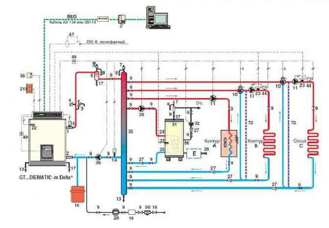
Whether it is an industrial building or a residential building, you need to make competent calculations and draw up a diagram of the heating system circuit
At this stage, experts recommend paying special attention to the calculation of the possible heat load on the heating circuit, as well as the amount of fuel consumed and heat generated.
Main Factors
An ideally calculated and designed heating system must maintain the set temperature in the room and compensate for the resulting heat losses. When calculating the indicator of the heat load on the heating system in the building, you need to take into account:
Purpose of the building: residential or industrial.
Characteristics of the structural elements of the structure. These are windows, walls, doors, roof and ventilation system.
Housing dimensions. The larger it is, the more powerful the heating system should be. Be sure to take into account the area of window openings, doors, exterior walls and the volume of each interior space.
The presence of rooms for special purposes (bath, sauna, etc.).
Degree of equipment with technical devices. That is, the presence of hot water, ventilation systems, air conditioning and the type of heating system.
For a single room. For example, in rooms intended for storage, it is not necessary to maintain a comfortable temperature for a person.
Number of points with hot water supply. The more of them, the more the system is loaded.
Area of glazed surfaces. Rooms with French windows lose a significant amount of heat.
Additional terms. In residential buildings, this can be the number of rooms, balconies and loggias and bathrooms. In industrial - the number of working days in a calendar year, shifts, the technological chain of the production process, etc.
Climatic conditions of the region. When calculating heat losses, street temperatures are taken into account. If the differences are insignificant, then a small amount of energy will be spent on compensation. While at -40 ° C outside the window it will require significant expenses.
Heat meters
Now let's find out what information is needed in order to calculate the heating. It is easy to guess what this information is.
1. The temperature of the working fluid at the outlet / inlet of a particular section of the line.
2. The flow rate of the working fluid that passes through the heating devices.
The flow rate is determined through the use of thermal metering devices, that is, meters. These can be of two types, let's get acquainted with them.
Vane meters
Such devices are intended not only for heating systems, but also for hot water supply. Their only difference from those meters that are used for cold water is the material from which the impeller is made - in this case it is more resistant to elevated temperatures.

As for the mechanism of work, it is almost the same:
- due to the circulation of the working fluid, the impeller begins to rotate;
- the rotation of the impeller is transferred to the accounting mechanism;
- the transfer is carried out without direct interaction, but with the help of a permanent magnet.
Despite the fact that the design of such counters is extremely simple, their response threshold is quite low, moreover, there is reliable protection against distortion of readings: the slightest attempt to brake the impeller by means of an external magnetic field is stopped thanks to the antimagnetic screen.
Instruments with differential recorder
Such devices operate on the basis of Bernoulli's law, which states that the speed of a gas or liquid flow is inversely proportional to its static movement. But how is this hydrodynamic property applicable to the calculation of the flow rate of the working fluid? Very simple - you just need to block her path with a retaining washer. In this case, the rate of pressure drop on this washer will be inversely proportional to the speed of the moving stream. And if the pressure is recorded by two sensors at once, then you can easily determine the flow rate, and in real time.

Note! The design of the counter implies the presence of electronics.The overwhelming majority of such modern models provide not only dry information (temperature of the working fluid, its consumption), but also determine the actual use of thermal energy.
The control module here is equipped with a port for connecting to a PC and can be configured manually.
Many readers will probably have a logical question: what if we are not talking about a closed heating system, but about an open one, in which selection for hot water supply is possible? How, in this case, to calculate Gcal for heating? The answer is quite obvious: here pressure sensors (as well as retaining washers) are placed simultaneously on both the supply and the “return”. And the difference in the flow rate of the working fluid will indicate the amount of heated water that was used for domestic needs.
How to reduce current heating costs
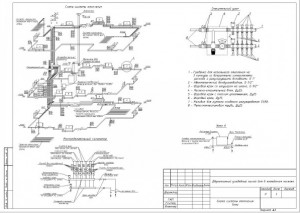
Scheme of central heating of an apartment building
Given the ever-increasing tariffs for housing and communal services for heat supply, the issue of reducing these costs becomes only more relevant every year. The problem of reducing costs lies in the specifics of the operation of a centralized system.
How to reduce the payment for heating and at the same time ensure the proper level of heating of the premises? First of all, you need to learn that the usual effective ways to reduce heat losses do not work for district heating. Those. if the facade of the house was insulated, the window structures were replaced with new ones - the amount of payment will remain the same.
The only way to reduce heating costs is to install individual heat meters. However, you may encounter the following problems:
- A large number of thermal risers in the apartment. Currently, the average cost of installing a heating meter ranges from 18 to 25 thousand rubles. In order to calculate the cost of heating for an individual device, they must be installed on each riser;
- Difficulty in obtaining permission to install a meter. To do this, it is necessary to obtain technical conditions and, on their basis, select the optimal model of the device;
- In order to make timely payment for heat supply according to an individual meter, it is necessary to periodically send them for verification. To do this, dismantling and subsequent installation of the device that has passed verification is carried out. This also entails additional costs.
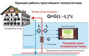
The principle of operation of a common house meter
But despite these factors, the installation of a heat meter will ultimately lead to a significant reduction in payment for heat supply services. If the house has a scheme with several heat risers passing through each apartment, you can install a common house meter. In this case, the cost reduction will not be so significant.
When calculating payment for heating according to a common house meter, it is not the amount of heat received that is taken into account, but the difference between it and in the return pipe of the system. This is the most acceptable and open way to form the final cost of the service. In addition, by choosing the optimal model of the device, you can further improve the heating system of the house according to the following indicators:
- The ability to control the amount of heat energy consumed in the building depending on external factors - the temperature in the street;
- A transparent way to calculate payment for heating. However, in this case, the total amount is distributed among all apartments in the house depending on their area, and not on the amount of thermal energy that came to each room.
In addition, only representatives of the management company can deal with the maintenance and configuration of the common house meter. However, residents have the right to demand all the necessary reporting for reconciliation of completed and accrued utility bills for heat supply.
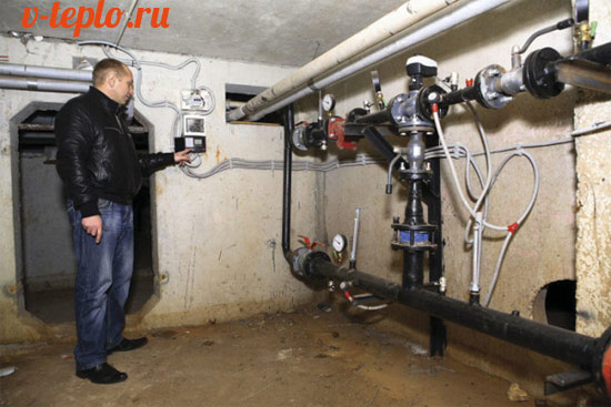
In addition to installing a heat meter, it is necessary to install a modern mixing unit to control the degree of heating of the coolant included in the heating system of the house.
4 Estimated heat loads of the school
Calculation of heating loads
Estimated hourly heat load
heating of a separate building is determined
according to aggregated indicators:
Qo=η∙α∙V∙q∙(tP-to)∙(1+Ki.r.)∙10-6
(3.6)
where - correction
difference factor
design outdoor temperature
for heating designofromto\u003d -30 ° С, at which it is determined
corresponding value is taken
according to Appendix 3, α=0.94;
V- volume of the building on the outside
measure, V=2361 m3;
qo—
specific heating characteristic
buildings ato= -30 °, accept qo=0,523
W/(m3∙◦С)
tP— design air temperature
in a heated building, we accept 16 ° С
tO— calculated outdoor temperature
air for heating design
(tO=-34◦С)
η- boiler efficiency;
Ki.r. — calculated coefficient
thermal infiltration
and wind pressure, i.e. ratio
heat loss from a building with infiltration
and heat transfer through external
fences at outdoor temperature
air calculated for design
heating. Calculated according to the formula:
Ki.r.=10-2∙[2∙g∙L∙(1-(273+to)/(273+tн))+ω]1/2
(3.7)
where g is the acceleration of the free
fall, m/s2;
L is the free height of the building,
take equal to 5 m;
ω - calculated for a given area
wind speed during the heating period,
ω=3m/s
Ki.r.=10-2∙[2∙9,81∙5∙(1-(273-34)/(273+16))+3]1/2=0,044
Qo=0,91∙0,94∙2361∙(16+34)∙(1+0,044)∙0,39
∙10-6=49622.647∙10-6W.
Calculation of ventilation loads
In the absence of a ventilated project
buildings estimated consumption those rafts on
ventilation, W [kcal / h], determined by
formula for enlarged calculations:
Qv =
Vnqv∙( ti — tO ),
(3.8 )
where vn —
volume of the building by external measurement, m3
;
qv - specific
ventilation characteristics of the building,
W/(m 3 °C)
[kcal/(h m3 °C)], taken according to
calculation; in the absence of data on the table.
6 for public buildings;
tj, —
average indoor air temperature
ventilated rooms of the building, 16 °C;
tO, - calculated
outdoor temperature for
heating design, -34°С,
Qv= 2361∙0,09(16+34)=10624,5
|
Determining the amount of heat |
|
|
Qhot water supply=1.2∙M∙(a+b)∙(tG-tX)∙cpcf/nc, |
where M is the estimated number of consumers;
a - the rate of water consumption per
hot water supply at a temperature
tG=
55 C
per person per day, kg/(day × person);
b - hot water consumption with
temperature tG=
55 C,
kg (l) for public buildings, referred
to one resident of the area; Without
more accurate data is recommended
take b = 25 kg per day for one
person, kg/(day × person);
cpcf=4.19
kJ/(kg×K) – specific heat capacity of water
at its average temperature tWed =
(tG-tX)/2;
tX–
temperature of cold water in heating
period (in the absence of data, it is accepted
equal to 5 C);
nc–
estimated duration of heat supply
for hot water supply, s/day; at
round the clock supply nc=24×3600=86400
With;
coefficient 1.2 takes into account
drying out of hot water in subscriber rooms
hot water systems.
Qhot water supply=1,2∙300∙
(5+25) ∙
(55-5)
∙4,19/86400=26187,5
Tue
Calculation formula
Thermal energy consumption standards
Thermal loads are calculated taking into account the power of the heating unit and the heat losses of the building. Therefore, in order to determine the capacity of the designed boiler, it is necessary to multiply the heat loss of the building by a multiplying factor of 1.2. This is a kind of margin equal to 20%.
Why is this ratio needed? With it, you can:
- Predict the drop in gas pressure in the pipeline. After all, in winter there are more consumers, and everyone tries to take more fuel than the rest.
- Vary the temperature inside the house.
We add that heat losses cannot be distributed evenly throughout the building structure. The difference in indicators can be quite large. Here are some examples:
- Up to 40% of the heat leaves the building through the outer walls.
- Through floors - up to 10%.
- The same applies to the roof.
- Through the ventilation system - up to 20%.
- Through doors and windows - 10%.
So, we figured out the design of the building and made one very important conclusion that heat losses that need to be compensated depend on the architecture of the house itself and its location. But much is also determined by the materials of the walls, roof and floor, as well as the presence or absence of thermal insulation.
This is an important factor.
For example, let's determine the coefficients that reduce heat loss, depending on window structures:
- Ordinary wooden windows with ordinary glass. To calculate the thermal energy in this case, a coefficient equal to 1.27 is used. That is, through this type of glazing, thermal energy leaks, equal to 27% of the total.
- If plastic windows with double-glazed windows are installed, then a coefficient of 1.0 is used.
- If plastic windows are installed from a six-chamber profile and with a three-chamber double-glazed window, then a coefficient of 0.85 is taken.
We go further, dealing with the windows. There is a certain relationship between the area of \u200b\u200bthe room and the area of \u200b\u200bwindow glazing. The larger the second position, the higher the heat loss of the building. And here there is a certain ratio:
- If the window area in relation to the floor area has only a 10% indicator, then a coefficient of 0.8 is used to calculate the heat output of the heating system.
- If the ratio is in the range of 10-19%, then a coefficient of 0.9 is applied.
- At 20% - 1.0.
- At 30% -2.
- At 40% - 1.4.
- At 50% - 1.5.
And that's just the windows. And there is also the effect of the materials that were used in the construction of the house on thermal loads. Let's arrange them in a table where wall materials will be located with a decrease in heat losses, which means that their coefficient will also decrease:
Type of building material
As you can see, the difference from the materials used is significant. Therefore, even at the stage of designing a house, it is necessary to determine exactly what material it will be built from. Of course, many developers build a house based on the budget allocated for construction. But with such layouts, it is worth reconsidering it. Experts assure that it is better to invest initially in order to later reap the benefits of savings from the operation of the house. Moreover, the heating system in winter is one of the main items of expenditure.
Room sizes and building heights
Heating system diagram
So, we continue to understand the coefficients that affect the formula for calculating heat. How does room size affect heat loads?
- If the ceiling height in your house does not exceed 2.5 meters, then a coefficient of 1.0 is taken into account in the calculation.
- At a height of 3 m, 1.05 is already taken. A slight difference, but it significantly affects heat loss if the total area of \u200b\u200bthe house is large enough.
- At 3.5 m - 1.1.
- At 4.5 m -2.
But such an indicator as the number of storeys of a building affects the heat loss of a room in different ways. Here it is necessary to take into account not only the number of floors, but also the location of the room, that is, on which floor it is located. For example, if this is a room on the ground floor, and the house itself has three or four floors, then a coefficient of 0.82 is used for the calculation.
When moving the room to the upper floors, the rate of heat loss also increases. In addition, you will have to take into account the attic - is it insulated or not.
As you can see, in order to accurately calculate the heat loss of a building, it is necessary to determine various factors. And all of them must be taken into account. By the way, we have not considered all the factors that reduce or increase heat losses. But the calculation formula itself will mainly depend on the area of \u200b\u200bthe heated house and on the indicator, which is called the specific value of heat losses. By the way, in this formula it is standard and equal to 100 W / m². All other components of the formula are coefficients.
Energy survey of the designed modes of operation of the heat supply system
When designing, the heat supply system of CJSC Termotron-zavod was designed for maximum loads.
The system was designed for 28 heat consumers. The peculiarity of the heat supply system is that part of the heat consumers from the outlet of the boiler house to the main building of the plant. Further, the heat consumer is the main building of the plant, and then the rest of the consumers are located behind the main building of the plant. That is, the main building of the plant is an internal heat consumer and a transit heat supply for the last group of heat load consumers.
The boiler house was designed for steam boilers DKVR 20-13 in the amount of 3 pieces, operating on natural gas, and hot water boilers PTVM-50 in the amount of 2 pieces.
One of the most important stages in the design of heat networks was the determination of the calculated heat loads.
The estimated heat consumption for heating each room can be determined in two ways:
- from the heat balance equation of the room;
- according to the specific heating characteristic of the building.
The design values of thermal loads were made according to aggregated indicators, based on the volume of buildings according to the invoice.
Estimated heat consumption for heating the i-th industrial premises, kW, is determined by the formula:
, (1)
where: - coefficient of accounting for the area of construction of the enterprise:
(2)
where - specific heating characteristic of the building, W / (m3.K);
— volume of the building, m3;
- design air temperature in the working area, ;
- the design temperature of the outside air for calculating the heating load, for the city of Bryansk is -24.
The calculation of the estimated heat consumption for heating for the premises of the enterprise was carried out according to the specific heating load (Table 1).
Table 1 Heat consumption for heating for all premises of the enterprise
|
No. p / p |
Object name |
Building volume, V, m3 |
Specific heating characteristic q0, W/m3K |
Coefficient e |
Heat consumption for heating , kW |
|
1 |
Canteen |
9894 |
0,33 |
1,07 |
146,58 |
|
2 |
Malyarka Research Institute |
888 |
0,66 |
1,07 |
26,46 |
|
3 |
NII TEN |
13608 |
0,33 |
1,07 |
201,81 |
|
4 |
El. engines |
7123 |
0,4 |
1,07 |
128,043 |
|
5 |
model plot |
105576 |
0,4 |
1,07 |
1897,8 |
|
6 |
Painting department |
15090 |
0,64 |
1,07 |
434,01 |
|
7 |
Galvanic department |
21208 |
0,64 |
1,07 |
609,98 |
|
8 |
harvesting area |
28196 |
0,47 |
1,07 |
595,55 |
|
9 |
thermal section |
13075 |
0,47 |
1,07 |
276,17 |
|
10 |
Compressor |
3861 |
0,50 |
1,07 |
86,76 |
|
11 |
Forced ventilation |
60000 |
0,50 |
1,07 |
1348,2 |
|
12 |
HR department extension |
100 |
0,43 |
1,07 |
1,93 |
|
13 |
Forced ventilation |
240000 |
0,50 |
1,07 |
5392,8 |
|
14 |
Packaging shop |
15552 |
0,50 |
1,07 |
349,45 |
|
15 |
plant management |
3672 |
0,43 |
1,07 |
70,96 |
|
16 |
Class |
180 |
0,43 |
1,07 |
3,48 |
|
17 |
Technical department |
200 |
0,43 |
1,07 |
3,86 |
|
18 |
Forced ventilation |
30000 |
0,50 |
1,07 |
674,1 |
|
19 |
Sharpening section |
2000 |
0,50 |
1,07 |
44,94 |
|
20 |
Garage - Lada and PCh |
1089 |
0,70 |
1,07 |
34,26 |
|
21 |
Liteyka /L.M.K./ |
90201 |
0,29 |
1,07 |
1175,55 |
|
22 |
Research institute garage |
4608 |
0,65 |
1,07 |
134,60 |
|
23 |
pump house |
2625 |
0,50 |
1,07 |
58,98 |
|
24 |
research institute |
44380 |
0,35 |
1,07 |
698,053 |
|
25 |
West - Lada |
360 |
0,60 |
1,07 |
9,707 |
|
26 |
PE "Kutepov" |
538,5 |
0,69 |
1,07 |
16,69 |
|
27 |
Leskhozmash |
43154 |
0,34 |
1,07 |
659,37 |
|
28 |
JSC K.P.D. build |
3700 |
0,47 |
1,07 |
78,15 |
TOTAL FOR THE PLANT:
Estimated heat consumption for heating CJSC "Termotron-Zavod" is:
The total heat generation for the entire enterprise is:
Estimated heat losses for the plant are determined as the sum of the estimated heat consumption for heating the entire enterprise and total heat emissions, and are:
Calculation of annual heat consumption for heating
Since CJSC "Termotron-zavod" worked in 1 shift and with days off, the annual heat consumption for heating is determined by the formula:
(3)
where: - average heat consumption of standby heating for the heating period, kW (standby heating provides the air temperature in the room);
, - the number of working and non-working hours for the heating period, respectively. The number of working hours is determined by multiplying the duration of the heating period by the coefficient for taking into account the number of working shifts per day and the number of working days per week.
The company works in one shift with days off.
(4)
Then
(5)
where: - average heat consumption for heating during the heating period, determined by the formula:
. (6)
Due to non-round-the-clock operation of the enterprise, the standby heating load is calculated for the average and design outdoor air temperatures, according to the formula:
; (7)
(8)
Then the annual heat consumption is determined by:
Graph of the adjusted heating load for the average and design outdoor temperatures:
; (9)
(10)
Determine the temperature of the beginning - end of the heating period
, (11)
Thus, we accept the temperature of the beginning of the end of the heating period = 8.