Combustion chambers of gas turbines as part of a GTU gas turbine unit
In the combustion chambers, the internal energy of the fuel during combustion is converted into the potential energy of the working fluid. Modern gas turbines use liquid or gaseous fuels. Combustion of fuel requires an oxidizing agent, which is oxygen in the air. Pressurized air enters the combustion chamber after the compressor.
When fuel is burned, high-temperature combustion gases are formed, which are mixed with additional air. The resulting hot gas (working fluid) is sent to the gas turbine.
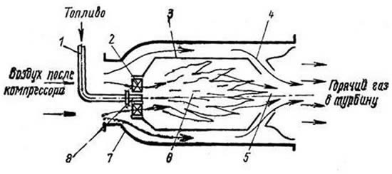
Fig.1. GTU combustion chamber: 1 - fuel supply, 2 - register, 3 - flame tube, 4 - mixer, 5 - mixing zone, 6 - combustion zone, 7 - housing, 8 - fuel dispenser (nozzle)
The simplest combustion chamber of a gas turbine plant (Fig. 1) consists of a fuel dispenser 8, a primary air register 2, a flame tube 3 and a mixer 4, which are located in a housing 7. The housing is loaded with pressure from the inside.
The fuel dispenser (burner or nozzle) 8 supplies fuel to the combustion zone 6. All air supplied to the combustion chamber is divided into two streams. A smaller part of the air (primary air) in the amount necessary to maintain the combustion process enters through register 2 into the combustion zone. Most of the air (secondary air) does not participate in the combustion process, but passes between the body 7 and the flame tube 3, cooling it. Then, after passing through the mixer 4, this air is mixed with the combustion products in the mixing zone 5, cooling them to a predetermined temperature.
The design of the combustion chamber of gas turbine plants depends on the purpose and scheme of the gas turbine, the parameters of its cycle and the type of fuel. At the same time, there are a number of features by which it is possible to divide the combustion chambers of gas turbines into several types.
Burnouts and deposits on the piston head diesel engine
Description of damage
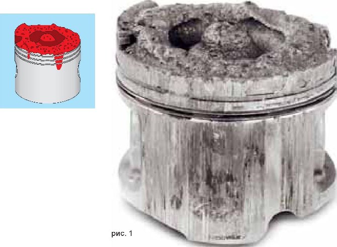
The zone of the bottom and the top zone is completely destroyed (Fig. 1). The hot zone burned out to the reinforcing insert. The molten piston material has moved along the piston skirt and caused damage and scuffing there as well. The reinforcing insert of the first compression ring was partially preserved only on the left side of the piston. Parts of the piston flew off with such force that they fell through the intake valve into the intake manifold and thus also into the adjacent cylinder and caused damage there (impact marks).
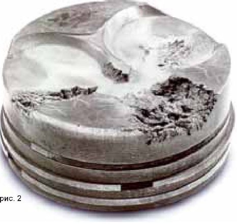
to fig. 2:
in the direction of injection by one or more jets of nozzles, erosive burnouts appeared on the piston bottom and on the edge of the heat zone. The piston skirt and piston ring area are free of burrs.
Damage assessment
Damage of this kind occurs especially in direct injection diesel engines. This applies to pre-chamber diesel engines only if one of the pre-chambers is damaged and, as a result, the pre-chamber engine turns into a direct injection engine. If the corresponding cylinder injector does not maintain injection pressure after
the end of the injection process and the pressure drops, vibrations in the high pressure fuel line can once again raise the nozzle needle, so that after the end of the injection process, fuel is injected again into the combustion chamber (mechanical injectors). If the oxygen in the combustion chamber is exhausted, then individual drops of fuel flow through the entire combustion chamber and fall on the bottom of the piston moving down closer to the edge. They quickly burn out there with a lack of oxygen, and quite a lot of heat is generated. At the same time, the material in these places softens. The dynamic forces and erosion of the fast-flowing combustion gases pull individual particles out of the surface (Fig.2) or remove the head completely resulting in the damage shown in fig. one.
Possible causes of damage
• Leaky nozzles or hard moving or stuck nozzle needles.
• broken or weakened injector springs.
• defective pressure reducing valves in the high pressure fuel pump
• The amount of fuel injected and the injection timing are not adjusted according to the engine manufacturer's instructions.
• in prechamber engines: a defect in the prechamber, but only in combination with one of the above reasons.
• ignition delay due to insufficient compression as a result of too much clearance, incorrect valve timing or leaking valves
• too long delay due to non-flammable diesel fuel (too low cetane number)
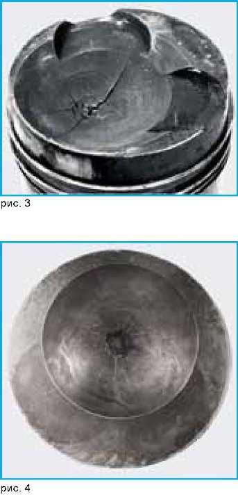
Cracks in the bottom and in the recesses of the bottom diesel engine
Description of damage
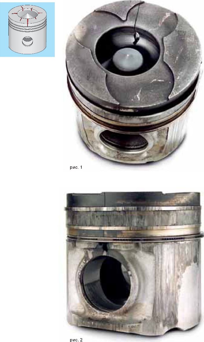
The piston head has a stress crack that extends unilaterally from the piston crown to the piston pin bore (fig. 1 and fig. 2). The hot combustion gases flowing through the crack burned a channel into the piston material, extending from the recess to the casting groove under the oil ring outward.
Damage assessment
Due to the high thermal load, the material of the pistons in the pre-chamber engine is very hot at the points of entry of the pre-chamber jets and in the direct injection engine at the edge of the recess. In hot places, the material expands more than in other places. Since the hot spots are surrounded by cold material, the material is subjected to permanent, out-of-elasticity deformation at the hot hot spot. When it cools down, the exact opposite happens. In places where the material was first subjected to compression and then extrusion, there is a sudden shortage of material. As a result, corresponding tensile stresses appear in this zone, which cause stress cracks (Fig. 3 and Fig. 4). If stresses from the deflection of the pin are superimposed on the stresses from thermal loading, sometimes a wide main crack is formed from the stress crack, which leads to complete breakage and failure of the piston.
Possible causes of damage
• defective or incorrect injectors, malfunctions of the high pressure fuel pump, damage to the prechamber.
• high temperature due to defects in the cooling system.
• defects in the engine brake or excessive use of it. Subsequently, overheating occurs.
• Insufficient cooling of pistons with a cooling duct, e.g. due to clogged or bent cooling oil nozzles.
• in engines with frequently changing loads, such as city buses, earthmoving machines, etc., these factors can be particularly critical.
• use of pistons of the wrong specification, e.g. installation of pistons without a cooling channel, although a piston with a cooling channel should have been used, installation of pistons from other manufacturers that are not reinforced with fiber inserts at the edge of the recess.
• installation of pistons with the wrong shape of the recess for the engine, see also paragraph "3.4.7 Seizure in the piston head due to the use of incorrect pistons".
The Burning Crusade instances
The first addition to World of Warcraft: The Burning Crusade brought not only new content, but a lot of changes in game mechanics. 5ppl have been radically redesigned. They have become more compact - smaller in size, instead of 7-8 bosses there are 3-4. In addition, another version appeared, designed for players of the 70th, highest level at that time - the heroic one. In heroic, trash and bosses hit harder and were fatter. These 5ppl were really difficult and for a long time became a model of the complexity of this format. When the oldfags talked about the complexity of the instances of the next addition, they often remembered the heroes of TVS.
Another feature of TVS instances was that they were arranged in "thematic" groups of 3-4 pieces. Let's say there were three instances in Hellfire Citadel, just like in neighboring Zangarmarsh. In a certain sense, this was convenient, because you didn’t have to cross half a continent if you and your friends decided to spend the evening running through the dungeons. We passed one - and two steps away is the entrance to another.
Another innovation concerned the plot. In order to please the fans a little, the developers made several instances, which were “excursions into the past”. Players could take part in key events in the history of the Warcraft universe. Two instances for five persons provided such an opportunity. Players helped Medivh open the Dark Portal in the Black Marsh and, again, help Thrall escape his imprisonment. The entrances to these instances were located in the Caverns of Time, a mysterious place that served as the home of the Bronze Dragonflight. What to say? An interesting and very successful design solution.
What else was the remarkable heroic 5ppl? A chain to gain access to raids. In order to get into the starting raid instance, Karazhan, it was necessary to collect several parts of the key in three heroic instances. And in order to get access to the heroics, you had to buy a key from the vendor that sold it, if you had a certain level of reputation. The matter did not end there, and all the heroes of TBC were somehow tied up in access to the raid content. In general, then heroic instances played a very important role in the development of content.
Hellfire Peninsula (Hellfire Citadel)

Instance for players levels 57-70
Click to enlarge

Instance for players levels 58-70
Click to enlarge

Instance for players levels 65-70
Click to enlarge

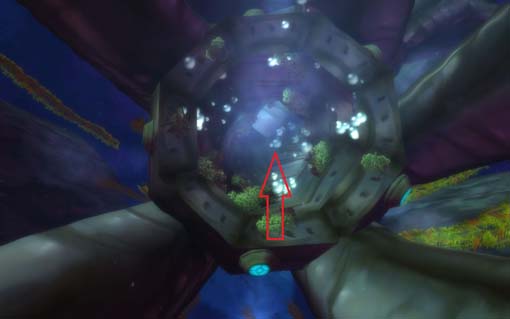
Zangarmarsh (Gnarfang Reservoir)

Dive here
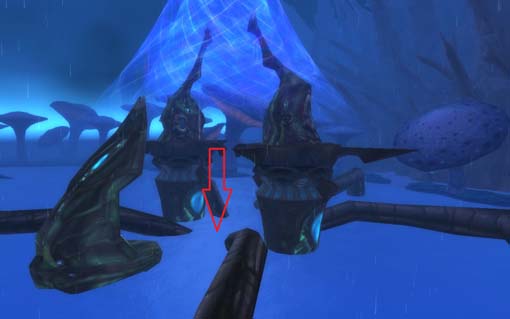
Swim all the way
Instance for players levels 65-70
Click to enlarge

Instance for players levels 59-70
Click to enlarge

Instance for players levels 60-70
Click to enlarge

Terrokar Forest (Aukindoun)

Instance for players levels 61-70
Click to enlarge

Instance for players levels 62-70
Click to enlarge

Instance for players levels 63-70
Click to enlarge

Instance for players levels 65-70
Click to enlarge

Tanaris (Caverns of Time)
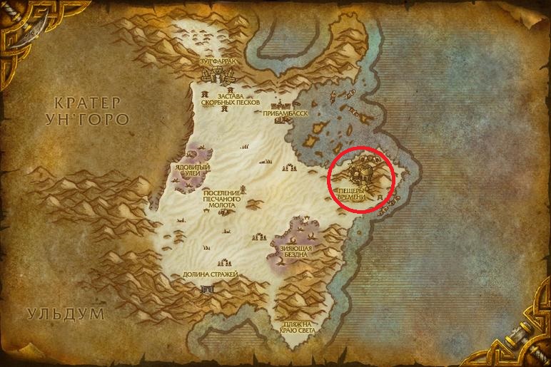
We go into the cave and sit on the dragon (before that, you must accept the quest). However, you can run on your own.
Instance for players levels 63-70
Click to enlarge

Instance for players levels 65-70
Click to enlarge

Netherstorm

Instance for players levels 65-70
Click to enlarge
Instance for players levels 65-70
Click to enlarge
Instance for players levels 65-70
Click to enlarge
Instance for players levels 65-70
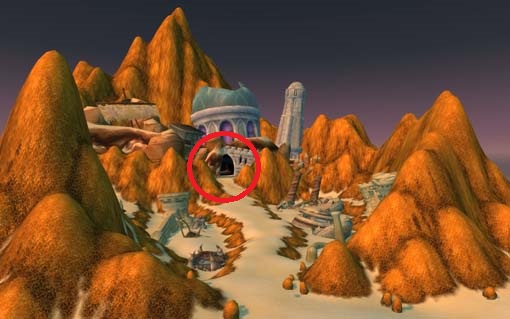
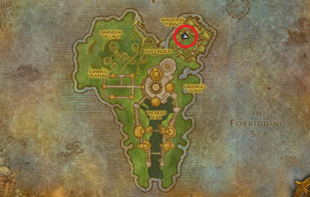
In order to get into the instance, you must first get to the Isle of Quel'Danas. You can get to it through a direct portal in Shatrratt. It is located in the same place as all the other portals. Next, look at the map and run in the right direction.
Another important innovation, which subsequently played a critical role, is worth mentioning separately. Bosses in heroics dropped Signs of Justice, for which you could buy epics from special vendors, and an epic fell out from the last boss
That is, if the player was unlucky in raids or had to dress up for them, then go ahead, farm badges. The system proved to be tenacious and subsequently used in all the following additions.
In the spring of 2008, as part of patch 2.4, the last 5ppl TBC was released - Magisters' Terrace. He was notable for two things. Firstly, there players again encountered Prince Kael'thas, who had risen from the ashes, who had previously been killed in Tempest Keep. Second, Kael'thas dropped a wingstrider mount.In the same patch, the need to have keys to raids was canceled (although the quests themselves remained).
Summarizing. TVS instance design became the standard for 5ppl in later expansions. He has not undergone fundamental changes either in WotLK or in Cataclysm. It was only in Mists of Pandaria that the developers decided that something needed to be changed, but this will be discussed in future releases.
Types of designs of combustion chambers
- Direct injection combustion chamber
- Indirect injection combustion chamber.
Direct injection combustion chamber
In a direct injection combustion chamber, fuel is injected directly at the closed end of the cylinder. Let's take a closer look at the open-type combustion chamber layout.
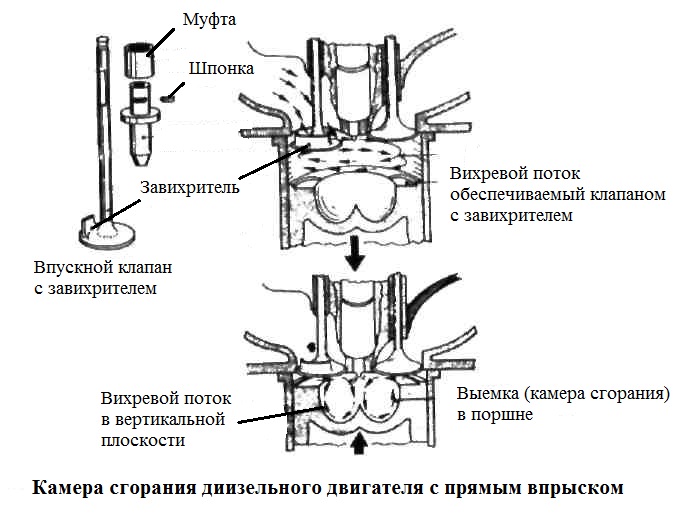
Combustion chambers were typically used on heavy vehicles, but after modification they were used on vehicles with a 2-liter engine. As you can see, the piston has a deep recess in which air is located at the moment when the piston is at TDC (top dead center) in close proximity to the cylinder head. Therefore, in order to obtain the required compression ratio, it is necessary to use an overhead valve mechanism. For cylinder heads, the piston head has shallow recesses to provide the necessary clearances. If the valves are incorrectly adjusted, the latter will hit the piston. A nozzle is used to supply finely atomized fuel with a pressure of 175 bar with an air stream, then the air-fuel mixture enters the piston recess (combustion chamber). The vortex in this case is formed in the vertical and horizontal planes.
When the piston rises, air enters the recess and moves approximately as shown in the figure. When the piston is at TDC, this movement is further accelerated by the swirl of the piston between the piston and the head. A horizontal or rotating swirl can be obtained by using a swirler on the intake valve.
The combination of two vortex flows creates a "circulation" of air in the recess and provides the necessary supply of oxygen to the combustion area.
Indirect injection combustion chamber
With indirect injection, the injection can be more even, due to which less injection pressure is needed. Indirect injection allows the engine to operate over a wide rev range.
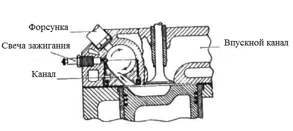
Ricardo Comet has designed most indirect injection combustion chambers. The indirect injection chambers have a swirl chamber, which is connected by a channel to the main chamber. Thanks to this, the design allows you to work with higher temperatures.
During the compression stroke, air is injected through the channel of the vortex chambers. Fuel is injected into the rapidly moving mass of air, after which it is sprayed into tiny particles. After combustion in the vortex chamber, the already burning fuel with unburned fuel enters the main combustion chamber, which is located in the piston crown. When the injection time is increased to maintain the required engine power, the main part of the fuel injected already at the end of the injection period is thoroughly mixed with the air in the main chamber and only then ignites. Due to this, the combustion period can continue for a long time until the fuel does not have enough oxygen for combustion. From this point on, black smog will begin to appear. It shows the maximum fuel that can be injected to run the engine at maximum power without compromising economy.
1 Combustion chamber housing
Combustion chamber housing I (Fig. 3.1) consists
from a shell with a spherical bottom and
snail welded to the shell 4 with two
air pipes. Frame
chamber in front of its flange
21 is attached to the flange 20 of the nozzle housing
compressor turbine apparatus.
To ensure the tightness of the connection,
flanges of the combustion chamber housings and
nozzle apparatus are covered
siloxane enamel.
The air pipes are fixed with their own
flanges to the compressor volute flanges.
To compensate for uneven thermal
extensions on the air pipes
5 (fig. 3.2) movable elements are installed
— multilayer bellows 4. Bellows
protected by 3 outer cups, which
protect the bellows from transverse
loads and ensure alignment of both
ends of the bellows. Inside the bellows
2 smooth glasses inserted to reduce
hydraulic losses. Production
deviations in the manufacture of flow
parts of engine components affect
temperature field uniformity
gas flow before the turbine and can
create local temperature increases
above the norm. In these cases, to align
temperature field apply
shims I, which
installed in the gap between
volute pipes and air supply
pipes. The washer closes with its segment
part of the working section, which allows
regulate the temperature field.
Fixing the washer from turning
provided with a pin pressed in
into the compressor volute flange. On the body
The chamber has two flanges: one 9 (Fig.
3.1)
in the center for fuel injector installation
and fastenings of the flame tube, the other 7 -
top right for attaching the launcher
igniter.
On the combustion chamber housing in front of the nozzle
eight
flanges 19 for mounting thermocouples and
fitting 24 for air sampling on the 3rd support.
When measuring the temperature field of gas
in front of the turbine in the flange holes
eight four-point
thermocouples After evaluation and debugging
temperature field, for constant
temperature control at
engine operation instead of
four-point thermocouples are installed
single point thermocouples. Indicators
of all eight thermocouples are averaged and
displayed on the index ITG-1.
To ensure the stability of readings
thermocouples in flange holes installed
safety sleeves 18, tight
entering the holes in the body of the nozzle
compressor turbine apparatus. bushings
prevent the entry of cold
air to the thermocouple inlet.
There is a flange at the bottom of the snail
16. for attaching the drain valve block.
With false and unsuccessful launches, do not
burnt fuel is collected at the bottom
point of the combustion chamber - in the cochlea, from where
through the holes in the flange 16 enters
into the drainage system. Housing and snail
made of stainless steel.