Control
The controlling organization is again heating networks.
What exactly do they control?
-
Several times during the winter, control measurements of the temperatures and pressures of the supply, return and mixture are carried out.
. In case of deviations from the temperature graph, the calculation of the heating elevator is carried out again with a bore or a decrease in the diameter of the nozzle. Of course, this should not be done at the peak of cold weather: at -40 on the street, driveway heating can catch ice within an hour after the circulation stops. -
In preparation for the heating season, the condition of the valves is checked
. The check is extremely simple: all valves in the assembly are closed, after which any control valve is opened. If water comes from it, you need to look for a malfunction; in addition, in any position of the valves, they should not have leaks through the stuffing boxes. - Finally, at the end of the heating season, the elevators in the heating system, along with the system itself, are tested for temperature
. When the DHW supply is turned off, the coolant heats up to maximum values.
Purpose and characteristics
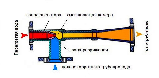
The heating elevator cools the superheated water to the calculated temperature, after which the prepared water enters the heating devices that are located in the living quarters. Water cooling occurs at the moment when hot water from the supply pipeline is mixed in the elevator with cooled water from the return.
The scheme of the heating elevator clearly shows that this unit contributes to an increase in the efficiency of the entire heating system of the building. It is entrusted with two functions at once - a mixer and a circulation pump. Such a node is inexpensive, it does not require electricity. But the elevator has several disadvantages:
- The pressure drop between the supply and return pipelines should be at the level of 0.8-2 bar.
- The outlet temperature cannot be adjusted.
- There must be an accurate calculation for each component of the elevator.
Elevators are widely applicable in municipal thermal economy, as they are stable in operation when the thermal and hydraulic regime changes in thermal networks. The heating elevator does not need to be constantly monitored, all adjustment consists in choosing the correct nozzle diameter.
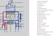
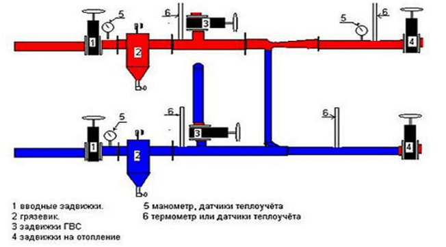
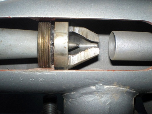
The heating elevator consists of three elements - a jet elevator, a nozzle and a rarefaction chamber. There is also such a thing as elevator strapping. The necessary shut-off valves, control thermometers and pressure gauges should be used here.
The selection of this type of heating elevator is due to the fact that here the mixing ratio varies from 2 to 5, in comparison with conventional elevators without nozzle control, this indicator remains unchanged. So, in the process of using elevators with an adjustable nozzle, you can slightly reduce heating costs.
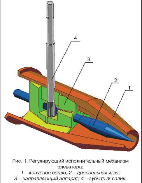
The design of this type of elevators incorporates a regulating actuator, which ensures the stability of the heating system at low flow rates of network water. In the cone-shaped nozzle of the elevator system, there is a regulating throttle needle and a guiding device that spins the water jet and plays the role of a throttle needle casing.
This mechanism has a motorized or manually rotated toothed roller. It is designed to move the throttle needle in the longitudinal direction of the nozzle, changing its effective cross section, after which the water flow is regulated. So, it is possible to increase the consumption of network water from the calculated indicator by 10-20%, or reduce it almost to the complete closure of the nozzle. Reducing the nozzle cross section can lead to an increase in the flow rate of the network water and the mixing ratio. So the temperature of the water drops.
The effect of installing washers
After installing the washers, the coolant flow through the pipelines of the heating network is reduced by 1.5-3 times. Accordingly, the number of operating pumps in the boiler room also decreases. This results in savings in fuel, electricity, chemicals for make-up water.It becomes possible to increase the temperature of the water at the outlet of the boiler room. For more information about setting up external heating networks and the scope of work, see ... ..Here you need to give a link to the section of the site "Setting up heating networks"
Pucking is necessary not only for regulating external heating networks, but also for the heating system inside buildings. The risers of the heating system, located further from the heat point located in the house, receive less hot water, it is cold in the apartments here. It is hot in apartments located close to the heat point, since more heat carrier is supplied to them. The distribution of coolant flow rates among risers in accordance with the required amount of heat is also carried out by calculating washers and installing them on risers.
Bucket elevator calculation
The calculation of the bucket elevator is carried out according to the method described in / /.
Vertical bucket elevator capacity Q= 5 t/h designed for transporting grain, grain density R=700 kg/m3 at lifting height H=11m.
We select a belt elevator with loading by scooping, with centrifugal unloading, with belt speed v = 1.7 m/s; deep buckets with filling factor c = 0.8.
We determine the capacity of the buckets per 1 m of the traction element according to the formula:
i Qp 5000
— = —— = ——— = 0,002
a 3.6vpmc 3,6 1,7 700 0,8
For the obtained capacity, type III buckets with a width of VTo = 280 mm, capacity i \u003d 4.2 l in increments t = 180 mm./ /. After choosing the buckets, we specify the speed. Finally v = 2.2 m/s. Tape width B = BTo + 100 =280+ 100 +380 mm.
Received value V corresponds to the nearest value according to the standard, equal to 400 mm.
The mass of cargo per 1 m of the traction element will be
Qp 100
q = —- = —— = 12.63kg/m.
3.6v 3,6 2,2
We calculate the preliminary power according to the formula:
Qp H q v2
Nbefore = —- (An + Vn - + Cn — )
367 QpH
Value q adopted based on the condition that buckets of type III will be used in the bucket elevator. Odds An= 1,14, Vn= 1,6, WITHn = 0.25 - coefficients depending on the type of bucket elevator (belt elevator with centrifugal unloading)
Nbefore =(5 30/367) (1.14 + 1.6 13.2/5 + 0.25 2.22/30) = 1.136 kW
According to the calculated value Nbefore determine the maximum tensile gain in the traction element
1000 Nbefore s efb
Smax =Snb = ———-
v(efb — 1)
where h = 0.8 - efficiency drive;
b \u003d 180 - wrap angle of the drive drum
f = 0.20 for a cast iron drum when the bucket elevator is operating in a humid atmosphere.
Smax =Snb = 1000 1.136 0.8 1.87/ ( 2.2 0.87) = 8879 N
Then the approximate number of pads z will
S max n
z = ——
B Kp
z= 8879 9 / 40 610 = 3,275.
The tape is selected with gaskets made of beltanite B-820 with TOR \u003d 610 N / cm, and the coefficient n = 9. The resulting number of pads is rounded up to z = 4.
We determine the load per 1 m, according to the formula for cotton tape
ql \u003d 1.1 V ( 1.25 z d1 + q2)
ql = 1.1 0.4 (1.5 4 + 3 + 1) = 4.4 kg/m.
Weight of buckets per 1 m of traction element with the weight of one type III bucket GTo = 1.5 kg will be
GTo 1,5
qTo = — = — = 8.33 kg/m
a 0,18
From here
q'= q + ql + qTo = 12.63 + 4.4 + 8.33 = 25.35 kg/m
idle branch
q"= ql + qTo = 4.4 + 8.33 \u003d 12.73 kg / m.
Traction calculation is carried out in accordance with the design scheme (Fig. 4.1.). The point with minimum tension will be point 2, i.e. S2 =Smin.
The resistance to scooping is determined by the formula, taking the diameter of the lower drum at z=4Db = 0.65 m.
Wh = Koud q g Db,
where q— mass of cargo per 1 m of the traction element, kg;
TOoud is the specific energy consumption for scooping, TOoud ? (6 h 10) Db
Db is the diameter of the lower drum.
Then
S3 = about S2 +W3 = 1.06S2 + Koud q g Db = 1,06 S2 + 8 0,65 12,63 9,81= =1,06 S2644
S4 =S3 + W3-4 =1.06S2 + 644 + q' g H = 1,06 S2+ 645 + 9,81 25,36 30= = 1,06 S2 + 8107
the value S1 we determine by going around the contour of the track against the movement of the tape, i.e.
S1 = S2 + W2-1 = S2 +q" gH = S2 + 9,81 12,73 30 = S2 +3746
Using the expression Snb ? SSat e fb , which in our case has the form S4 ? 1.84S1, we obtain the tension value at point 2, equal to 608N. Substituting the found value S2into the above expressions, we define S3\u003d 1288N, S4 \u003d 8751N, S1 \u003d 4354N.
Examination S3 from the condition GWell ? 2S taking into account l = 0.075 m, h = 0.16 m and h1 = 0.1m for this type of bucket shows the value S3 sufficient to provide pre-tensioning of the traction element. By found value S4 =Smax specify the value z = 8751 9 /(40 610) = 3,23 ? 4.
The obtained number of strips of the tape coincides with the pre-selected one, therefore, the traction calculation should not be performed again.
Determine the diameter of the drive drum
Dp.b. =125 z = 125 4 = 600 mm
and rounded up to the value of 630 mm according to GOST.
The drum rotation frequency will be
60v
n = --- = 60 2.2 / (3.14 0.63) = 66.73 rpm
p Dp.b.
Determine the value of the pole distance
895
h = --- = 895 / 66.732 = 0.2 m
n2
Dp.b.
Value h therefore the unloading is centrifugal.
2
We determine the power of the electric motor for the elevator drive, taking efficiency. transmission mechanism equal to 0.8,
o (S4 +S1) v
N= —— = 1.06 (8751 - 4354) 2.2 / (1000 0.8) = 1121 W
1000 s
By the magnitude of the calculated power, we select the electric motor AO 72-6-UP with a power of Nd = 1.1 kW s nd =980 rpm.
Stages of washing the heating system
- Hydraulic calculation of the heating system, calculation of washers
- Development of recommendations for improving the operation of the heat point, heating system
- Installation of control washers on risers (this work can be carried out by the customer independently)
- Verification of implementation of recommended activities
- Analysis of the new steady state after washing the heating system
- Correction of the size of washers in places where the required result is not achieved (by calculation)
- Dismantling washers requiring adjustment, installing new washers
On internal heating systems, washers can be installed both in winter and in summer. Check their work - only in the heating season.
Possible problems and malfunctions
Despite the strength of the devices, sometimes the elevator heating unit fails. Hot water and high pressure quickly find weaknesses and provoke breakdowns.
This inevitably happens when individual components are of inadequate quality, the nozzle diameter is incorrectly calculated, and also due to blockages.
Noise
The heating elevator, while working, can create noise. If this is observed, it means that cracks or burrs have formed in the outlet part of the nozzle during operation.
The reason for the appearance of irregularities lies in the misalignment of the nozzle caused by the supply of coolant under high pressure. This happens if the excess head is not throttled by the flow controller.
Temperature mismatch
The high-quality operation of the elevator can also be called into question when the temperature at the inlet and outlet differs too much from the temperature curve. Most likely, the reason for this is the oversized nozzle diameter.
Incorrect water flow
A faulty throttle will result in a change in water flow compared to the design value.
Such a violation is easy to determine by the change in temperature in the incoming and return pipeline systems. The problem is solved by repairing the flow regulator (throttle).
Faulty structural elements
If the scheme for connecting the heating system to an external heat main has an independent form, then the cause of poor-quality operation of the elevator unit can be caused by faulty pumps, water heating units, shut-off and safety valves, all kinds of leaks in pipelines and equipment, malfunction of regulators.
The main reasons that negatively affect the scheme and principle of operation of pumps include the destruction of elastic couplings in the joints of the pump and motor shafts, the wear of ball bearings and the destruction of seats under them, the formation of fistulas and cracks on the housing, and the aging of seals. Most of the listed faults are repaired.
Unsatisfactory operation of water heaters is observed when the tightness of the pipes is broken, they are destroyed or the tube bundle sticks together. The solution to the problem is to replace the pipes.
Blockages
Blockages are one of the most common causes of poor heat supply. Their formation is associated with the ingress of dirt into the system when the dirt filters are faulty. Increase the problem and deposits of corrosion products inside the pipes.
The level of clogging of filters can be determined by the readings of pressure gauges installed before and after the filter. A significant pressure drop will confirm or refute the assumption of the degree of clogging. To clean the filters, it is enough to remove the dirt through the drain devices located in the lower part of the housing.
Any problems with pipelines and heating equipment must be repaired immediately.
Minor remarks that do not affect the operation of the heating system are necessarily recorded in special documentation, they are included in the plan for current or major repairs. Repair and elimination of comments takes place in the summer before the start of the next heating season.
2 Advantages and disadvantages of such a node
The elevator, like any other system, has certain strengths and weaknesses.
Such an element of the thermal system has become widespread thanks to a number of advantages,
among them:
- simplicity of the device circuit;
- minimal system maintenance;
- durability of the device;
- affordable price;
- independence from electric current;
- the mixing coefficient does not depend on the hydro-thermal regime of the external environment;
- the presence of an additional function: the node can play the role of a circulation pump.
The disadvantages of this technology are:
- the inability to adjust the temperature of the coolant at the outlet;
- rather time-consuming procedure for calculating the diameter of the nozzle-cone, as well as the dimensions of the mixing chamber.
The elevator also has a small nuance regarding installation - the pressure drop between the supply line and the return should be in the range of 0.8-2 atm.
2.1
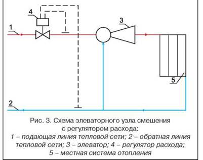
Scheme of connecting the elevator unit to the heating system
Heating and hot water (DHW) systems are somewhat interconnected. As mentioned above, the heating system requires a water temperature of up to 95 ° C, and in hot water at the level of 60-65 ° C. Therefore, the use of an elevator assembly is also required here.
In any building connected to a centralized heating network (or boiler room), there is an elevator unit. The main function of this device is to lower the temperature of the coolant while increasing the volume of pumped water in the house system.
Task Calculation of a belt bucket elevator with a solution
Calculate a belt bucket elevator for transporting bulk feed according to the following characteristics:
Material: oats;
Elevator height: 15 meters;
Productivity: 30 t/h.
Payment.
To lift oats, according to the recommendations, a belt traction body with spaced deep buckets with centrifugal unloading can be adopted. (: table 7.7)
We accept the speed of the tape V = 2.5 m / s
According to the recommendations of prof. N. K. Fadeeva, for high-speed elevators with centrifugal unloading. Drum diameter
Db \u003d 0.204 * V2 \u003d 0.204 * 2.52 \u003d 1.28 m
We accept the diameter of the drive drum Db = 1000mm adj. LXXXVII). we accept the end drum of the same diameter.
Drum speed:
nb===47.8 min-1
Pole distance
Since b (drum radius), centrifugal unloading takes place, which corresponds to the previously specified condition.
Linear capacity of buckets:
 l/m
l/m
P is the productivity of the elevator, t/h;
— bulk density of cargo, t/m3
- bucket fill factor (1: tab. 77)
According to the table 79 for = 6.8 we choose a deep bucket with a capacity of i0 = 4l, bucket width Bk = 320 mm, bucket spacing a = 500 mm, belt width B = 400 mm.
According to the table 80 select the bucket reach A=15 mm, bucket height h=0mm, bucket radius R=60mm.
Number of pads i:
We accept i=6
Linear weight of the tape:
qo=1.1*B*(i+1+2)=1.1*0.4*(1.5*6+3+1.5)=5.9 kgf/m.
Linear weight of the belt with buckets:
qx=K*P=0.45*30=13.5 kgf/m.
K-factor, its values are given in (1: tab. 78)
Linear loading from the lifted load
q= egs/m
Linear load on the working branch: qp=qx+q=13.5+3.3=16.9 kgf/m;
Traction calculation is performed by the contour bypass method. When the drive drum is rotated clockwise, the minimum tension will be at point 2. See the diagram in Figure 1.
Fig 1. Layout of the checked tension points in the tape.
The tension at point 3 is defined as:
S3=K*S2+W3=1.08*S2+13.2
W3 - load scooping resistance
W3=p3*q=4*3.3=13.2 kgf;
Р3-scooping coefficient, we accept р3=4 kgf*m/kgf
K1 is the coefficient of tension increase in the belt with buckets when rounding the drum.
Tension at point 4
S4=Snb=S3+qp*H=1.08*S2+13.2+16.9*1.5=1.08*S2+267
Tension at point 1
S1=Sb=S2+qx*H=S2+13.5*15=S2+203
For friction drive with flexible coupling
Snb Sb*eFa
Between belt and steel drum in humid air F=0.2. Tape wrapping angle of drive drum =180o;
ЕFa=2.710.2*3.14=1.87 (1: adj. LXXXI), then
Snb1.87*Sb;
1.08*S2+2671.87*(S2+203);
1.08*S2+2671.87*S2+380;
0.79*S2-113
S2-143 kgf
The minimum tension in the belt from the condition of normal scooping of the load must satisfy the condition:
S2=Smin5*q=5*3.3=16.5 kgf
We accept S2=25 kgf
With an increase in tension in the tape, the margin of the traction capacity of the drive increased slightly. The tension at other points of the contour will be:
S1=S2+203=25+203=228 kgf
S3=1.08*S2+13.2=1.08*25+13.2=40.2 kgf
S4=S3+qp*H=40.2+16.9*15=294 kgf
According to the maximum effort, we specify the number of gaskets in the tape
The margin of safety of the belt is taken as for an inclined conveyor (1: table 55). n=12, =55 kgf/cm
B-820 with the number of spacers i=2, width B=400 mm, K0=0.85 - coefficient taking into account the weakening of the tape by holes for rivets.
Tension drum stroke for belting belt:
m
Tension force applied to the end drum:
pH=S2+S3=25+40.2=65.2 kgf
Traction force on the drive shaft of the drum (taking into account the efforts on the own rotation of the drum):
W0=S4-S1+(K/-1)*(S4-S1)=294-228+(1.08-1)*(294+228)=108 kgf
K/-factor, which takes into account the resistance to rotation of the drive drum.
Calculation formula of the engine:
Np=kW
Installed motor power:
N0=ny*Np=1.2*3.1=3.7 kW
ny-power margin 1.1…..1.2
We accept the engine type MTH 311-6
N=7kW, n=965min-1(=101 rad/s),
Jp=0.0229 kgf*m*s2 (1: app. XXXV).
Elevator Drive Gear Ratio
Ir. r.==
We choose the VK-400 gearbox. Execution III. Gear ratio Ir=21. (1: App. LXIV)/
The principle of operation and the diagram of the node
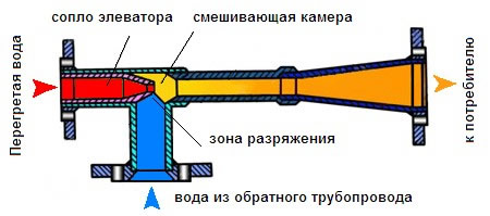
The hot water entering the residential building has a temperature corresponding to the temperature schedule of the combined heat and power plant. Having overcome the valves and mud filters, superheated water enters the steel housing, and then through the nozzle into the chamber, where mixing takes place. The pressure difference pushes the water jet into the expanded part of the body, while it is connected to the cooled coolant from the heating system of the building.
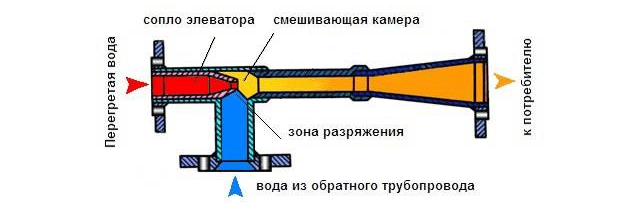
The superheated coolant, having a reduced pressure, flows at high speed through the nozzle into the mixing chamber, creating a vacuum. As a result, the effect of injection (suction) of the coolant from the return pipeline occurs in the chamber behind the jet. The result of mixing is water at the design temperature, which enters the apartments.
The scheme of the elevator device gives a detailed idea of the functionality of this apparatus.
Advantages of water jet elevators
A feature of the elevator is the simultaneous performance of two tasks: to work as a mixer and as a circulation pump. It is noteworthy that the elevator unit operates without the cost of electricity, since the principle of operation of the installation is based on the use of a pressure drop at the inlet.
The use of water jet devices has its advantages:
- simple design;
- low cost;
- reliability;
- no need for electricity.
Using the latest models of elevators equipped with automation, you can significantly save heat. This is achieved by controlling the temperature of the coolant in the zone of its outlet. To achieve this goal, you can lower the temperature in apartments at night or during the daytime, when most people are at work, study, etc.
The economical elevator unit differs from the conventional version by the presence of an adjustable nozzle. These parts can have a different design and level of adjustment. The mixing ratio for an apparatus with an adjustable nozzle varies from 2 to 6. As practice has shown, this is quite enough for the heating system of a residential building.
The choice of material for ETA-P elevator parts
When choosing a material for a particular part, they take into account the nature and magnitude of the load acting on the part, the method of manufacture, the requirements for wear resistance, the conditions for its operation, etc.
Particular attention is paid to ensuring static and fatigue strength, as the service life of parts ranges from 10 to 25 years. For the manufacture of elevators, high-quality carbon structural steel grades 30, 35, 40, 45, 40X and 40XH are used.
They are used in the normalized state for the manufacture of parts that experience relatively low stresses, and after hardening and high tempering - for the manufacture of more loaded parts. Steel grades 30 and 35 are subjected to normalization with a temperature of 880 - 900 ° C; hardening is carried out in water with a temperature of 860 - 880 ° C and tempering at 550 - 660 ° C. Parts made of steel grades 40 and 45 are subjected to normalization at a temperature of 860-880°C or quenching in water at a temperature of 840-860°C, followed by tempering; tempering temperature is assigned depending on the required mechanical properties.
How the elevator works
In simple words, the elevator in the heating system is a water pump that does not require external energy supply. Thanks to this, and even a simple design and low cost, the element found its place in almost all heating points that were built in the Soviet era. But for its reliable operation, certain conditions are needed, which will be discussed below.
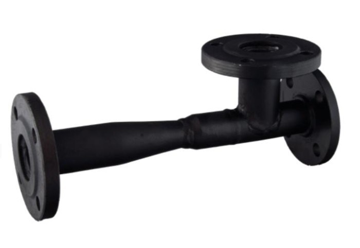
To understand the device of the heating system elevator, you should study the diagram shown above in the figure. The unit is somewhat reminiscent of an ordinary tee and is installed on the supply pipeline, with its side outlet it joins the return line. Only through a simple tee would water from the network pass immediately to the return pipeline and directly to the heating system without lowering the temperature, which is unacceptable.
A standard elevator consists of a supply pipe (pre-chamber) with a built-in nozzle of the calculated diameter and a mixing chamber, where the cooled coolant is supplied from the return. At the outlet of the node, the branch pipe expands, forming a diffuser. The unit operates as follows:
- the coolant from the network with a high temperature is sent to the nozzle;
- when passing through a hole of small diameter, the flow velocity increases, due to which a rarefaction zone appears behind the nozzle;
- rarefaction causes suction of water from the return pipeline;
- the flows are mixed in the chamber and exit the heating system through a diffuser.
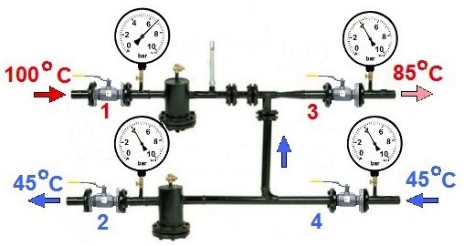
How the described process takes place is clearly shown by the diagram of the elevator node, where all flows are indicated in different colors:
An indispensable condition for the stable operation of the unit is that the pressure drop between the supply and return lines of the heat supply network is greater than the hydraulic resistance of the heating system.
Along with the obvious advantages, this mixing unit has one significant drawback. The fact is that the principle of operation of the heating elevator does not allow you to control the temperature of the mixture at the outlet. After all, what is needed for this? If necessary, change the amount of superheated coolant from the network and sucked water from the return. For example, in order to lower the temperature, it is necessary to reduce the flow rate at the supply and increase the flow of coolant through the jumper. This can only be achieved by reducing the nozzle diameter, which is impossible.
Electric elevators help to solve the problem of quality regulation. In them, by means of a mechanical drive rotated by an electric motor, the diameter of the nozzle increases or decreases. This is realized by means of a cone-shaped throttling needle that enters the nozzle from the inside for a certain distance. Below is a diagram of a heating elevator with the ability to control the temperature of the mixture:
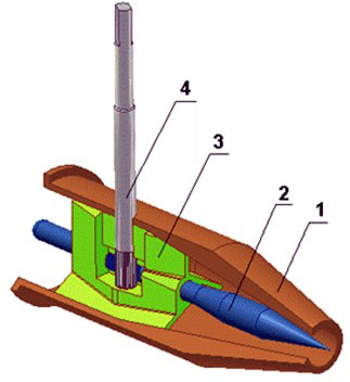
1 - nozzle; 2 - throttle needle; 3 - housing of the actuator with guides; 4 - shaft with gear drive.
A relatively recently appeared adjustable heating elevator allows the modernization of heating points without a radical replacement of equipment.Considering how many more such nodes operate in the CIS, such units are becoming increasingly important.
Calculation of the heating elevator
It should be noted that the calculation of a water jet pump, which is an elevator, is considered rather cumbersome, we will try to present it in an accessible form. So, for the selection of the unit, two main characteristics of the elevators are important for us - the internal size of the mixing chamber and the bore diameter of the nozzle. The camera size is determined by the formula:
- dr is the desired diameter, cm;
- Gpr is the reduced amount of mixed water, t/h.
In turn, the reduced consumption is calculated as follows:
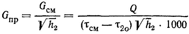
In this formula:
- τcm is the temperature of the mixture used for heating, °С;
- τ20 is the temperature of the cooled coolant in the return, °С;
- h2 - resistance of the heating system, m. Art.;
- Q is the required heat consumption, kcal/h.
To select the elevator unit of the heating system according to the size of the nozzle, it is necessary to calculate it according to the formula:
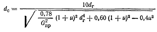
- dr is the diameter of the mixing chamber, cm;
- Gpr is the reduced consumption of mixed water, t/h;
- u is the dimensionless injection (mixing) coefficient.
The first 2 parameters are already known, it remains only to find the value of the mixing coefficient:
In this formula:
- τ1 is the temperature of the superheated coolant at the elevator inlet;
- τcm, τ20 - the same as in the previous formulas.
Based on the results obtained, the selection of the unit is carried out according to two main characteristics. The standard sizes of elevators are indicated by numbers from 1 to 7, it is necessary to take the one that is closest to the design parameters.
ETA-P elevator strength calculation
We will calculate the strength of the ETA-P elevator with a carrying capacity of 50 tons (Q=500 kN). Using the same technique, you can calculate the elevator of any size.
Design load
P = Q • K = 500 • 1.25 = 625 kN,
where K is a coefficient that takes into account dynamic forces and light sticking, K = 1.25
Elevator body. Material 35HML
Body shoulder (figure 5.1)
We calculate the support area for the action of crushing, shearing and bending stresses.
Figure 5.1 - Body collar
usm = , MPa (5.1)
where is the area of action of the load on the body, mm².
= , mm² (5.2)
where is the inner diameter of the body collar, D1=132 mm;
- outer diameter of the grip, D2=95 mm.
F1 \u003d 0.59 • (1322 - 952) \u003d 4955 mm²
According to formula 5.1:
usm = = 126 MPa,
Section a - a
usr = , MPa (5.3)
where is the cut area, mm²
, mm² (5.4)
where h is the height of the shoulder, mm
F2=0.75•р•132•30=9326 mm2..
By formula 5.3 we get
usr==67 MPa.
vizg = , MPa (5.5)
where Мizg — bending moment, N mm
Mizg = , N•mm (5.6)
Wizg - section modulus, mmі
Wizg =, mmі (5.7)
Mizg = N•mm
Wizg = mmі
Substituting into formula 5.5 we get
wizg = = 124 MPa.
Body lug
Figure 5.2 - Case lugs
Dangerous section b-b subject to tensile stresses
usm = , MPa (5.8)
where d is the diameter of the hole for the finger, d=35 mm;
e is the thickness of the lug, e = 22 mm.
usm = = 406 MPa.
Mechanical characteristics of the body casting:
ut = 550 MPa, uv = 700 MPa
= = 423 MPa;
cf \u003d / 2 \u003d 432/2 \u003d 212 MPa,
where k is the safety factor, k = 1.3.
Elevator earring
Material 40HN. Mechanical characteristics: ut = 785 MPa, uv = 980 MPa.
The earring (figure 5.3) is subjected to the pressure force of the link P and two forces P / 2 applied to the eyelets of the earring. Due to the presence of deformation, the earring is in contact with the link along the length of the arc, measured by angle b, and horizontal bursting forces Q appear in the eyelets of the earring. Complex mathematical calculations are necessary to determine the forces Q. The magnitude of the angle 6 and the law of pressure distribution along the arc measured by angle 6 and the law of pressure distribution along the arc measured by angle 6 are unknown. Their theoretical definition is difficult. Simplistically, we calculate the earring without taking into account the influence of deformations from the action of forces Q.
Figure 5.3 - Earring of the elevator
Eyelets of the earring, dangerous section ah-ah
Tensile stresses
ur = , MPa (5.9)
where c is the thickness of the outer part of the lug, c = 17 mm;
d is the thickness of the inner part of the lug, d = 12 mm;
R - outer radius, R = 40 mm
r - inner radius, r = 17.5 mm
ur
Using the Lame formula, we determine the greatest tensile stresses ur at point b from the forces of internal pressure (finger pressure).
ur = , MPa (5.10)
where q is the intensity of internal pressure forces.
q = , MPa (5.11)
q = MPa.
According to formula 5.10 we get
ur=MPa.
Rectilinear part I - I to II - II. In section II - II, tensile stresses act.
ur = , MPa (5.12)
where D is the diameter of the straight part of the earring, D = 40 mm.
ur = MPa.
\u003d ur / k \u003d 785 / 1.3 \u003d 604 MPa
cf = /2 = 604/2 = 302 MPa.
Thus, having calculated the strength of the elevator, it can be seen that when the rated load capacity is exceeded by 25%, the stresses, and especially in dangerous sections, do not exceed the permissible strength limits. The steel material used in the manufacture of the elevator is the most optimal.