Definition of the concept of pressure
Pump characteristics form.
Different slopes with identical casing and pump impeller (e.g. depending on motor speed)
Various flow and pressure changes
Pump head (H)
- specific mechanical work transmitted by the pump of the pumped liquid.
H=E/G
E
= mechanical energy
G
= weight of pumped liquid
The pressure created by the pump and the flow rate of the pumped liquid (supply) depend on each other. This relationship is displayed graphically as a pump curve. The vertical axis (y-axis) reflects the pump head (H) expressed in meters. Other pressure scales are also possible. In this case, the following relations are valid:
10 m w.st. = 1 bar = 100,000 Pa = 100 kPa
The horizontal axis (abscissa) shows the scale of pump delivery (Q), expressed in cubic meters per hour [m3/h]. Other delivery scales are also possible, eg [l/s].
The characteristic form shows the following types of dependence: the energy of the electric drive (taking into account the overall efficiency) is converted in the pump into such forms of hydraulic energy as pressure and speed. If the pump is running with the valve closed, it generates maximum pressure. In this case, one speaks of the pump head Ho at zero flow. When the valve begins to slowly open, the pumped medium begins to move. Due to this part drive energy is converted into kinetic energy liquids. Maintaining the initial pressure becomes impossible.
The pump characteristic takes the form of a falling curve. Theoretically, the pump characteristic intersects with the delivery axis. Then the water has only kinetic energy, that is, pressure is no longer created. However, since there is always internal resistance in the piping system, in reality the performance of the pumps is cut off before the delivery axis is reached.
Submersible pump power and efficiency
The rated efficiency of the electric motor of a centrifugal pump for water supply is the ratio of useful power to that which is consumed. Designation - η. Distribution formula: η = (Р2/Р1) * 100. The efficiency of an electric motor will never be higher than unity (100%) under any circumstances, since there is no “perpetual motion machine”, and any drives have losses.
Efficiency - this is the name of the ratio of hydraulics to the power that is supplied to the shaft of the downhole device, and their difference reports losses in the unit. Formula: η \u003d (P4 / P3) * 100.
The loss of power in a centrifugal pumping device is also obtained from a number of components, namely:
- hydraulic;
- Mechanical;
- Volume loss Pvset.
 Submersible pumps for summer cottages can be bought at any specialized store
The total efficiency is the sum of the efficiency of all losses. The efficiency of the device characterizes the degree of design perfection in terms of mechanics and hydraulics.
Can installation affect the amount of pressure
Given the simplicity, even primitive design of the pumps, as well as the availability of detailed installation instructions, many modern men take up the work on their own, that is, without the help of professionals. This behavior is most often associated with a desire to save money: not everyone is ready to pay not only for a pump or a pumping station, but also for the services of a master. Considering that the pressure of the pump is the main characteristic of its activity, no one is ready to lose. That is why the question arises by itself: how much installation carried out independently can affect the magnitude of the pressure.
It would seem that we connect one pipe to the suction pipe, the other to what is responsible for the pressure, supply power - and you're done. In practice, the slightest mistake can not only adversely affect the pressure of water, but also significantly reduce the duration of work.
Types of device power for a well
During the production of devices at the factory, the designations of the varieties of power are used:
- P1 (kW). Input electrical power is that which the electric motor takes from the mains.
- P2 (kW). On the motor shaft - the one that it gives to the shaft. The pump power input P1 is equal to the motor shaft power P2 divided by the efficiency of the motor.
- P3 (kW). The input value of the hydraulic pump is equal to P2 when the coupling that connects the device shaft and the motor shaft does not consume electricity.
- P4 (kW). The useful power of submersible hydraulic pumping equipment is the one that comes out during operation in the form of water flow and pressure.
 Without relevant experience, it is not recommended to independently install the pump
You can calculate the indicator online, there is a special calculator.
Equivalent hole
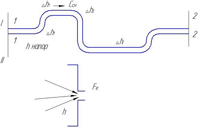

If done
hole section Fethrough which such
the same amount of air ,
,
as well as through the pipeline at the same
initial head h, then
such a hole is called equivalent,
those. passage through a given equivalent
hole replaces all resistances
in the pipeline.
Let's find the value
holes:
 ,
,
(4)
where c is the speed
gas outflow.
Gas consumption:
 (5)
(5)
From (2)
 (6)
(6)
Approximately because
that we do not take into account the narrowing factor
jets.
 —
—
is the conditional resistance
convenient to enter into calculations when simplifying
real complex systems. Losses
pressure in pipelines are determined
as the sum of losses in separate places
pipeline and are calculated for
based on experimental data,
given in the handbooks.
Losses in the pipeline
occur at turns, bends,
expansion and contraction of pipelines.
Losses in equal pipeline also
calculated according to reference data:
 (7)
(7)
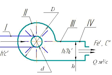
- Suction
pipe branch - Fan housing
- Discharge
pipe branch - equivalent
hole replacing the real
pipeline with its resistance.
- ;
- ;
- ;
- ;
- ;
 —
—
speed in the suction pipeline;
 —
—
exhaust velocity through the equivalent
hole;
 —
—
the amount of pressure under which
gas movement in the suction pipe;
 static and
dynamic pressure in the outlet pipe;
 —
—
full pressure in the discharge pipe.
Through the equivalent
hole
 gas leaks under pressure
 ,
,
knowing ,
,
find .
.
Example
What does
motor power to drive
fan, if we know the previous
data from 5.

Taking into account losses:

where
 —
—
monometric coefficient of useful
actions.

where
 —
—
theoretical fan head.


Derivation of Equations
fan.
Given:

Find: 
Competent selection of the unit according to the parameters
The selection of a pump for the conditions that are given is an important stage in the design of the installation and station. To select a unit for installation, you need to have the initial values that characterize the pipeline systems, and the requirements that apply to the project.
Such data, which is compiled in the form of a project, should include:
- Information about the purpose and nature of the operation of the device.
- Characteristics of the hydraulics of the pipeline system, including the capacity consumed by the maximum and minimum station Qmax and Qmin consumed head, which corresponds to the maximum and minimum flow rates Hmax and Hmin.
- Data about power sources or reservoirs.
- Data on the location and conditions of the location of the pump.
- Data about electric motors and energy sources.
- Special requirements. Based on this information, using catalogs and reference books on pumping equipment, you can select a device according to its characteristics and speed coefficient.
Primarily, the type and brand of the pump are selected according to the summary schedule of the working areas of the destination equipment that corresponds to it. The choice is made for averaged flow and head data.When selecting a coordinate with points Qcp and Hcp, it is necessary to ensure that it passes in the middle of the working field of the selected device.
 In order for the pump to serve for a long time, worn parts should be changed in time
Having applied the catalog, it is necessary to find the operating characteristic of the selected device and build a joint characteristic of it and the pipeline (well). By this alignment, the working coordinate is obtained, which corresponds to Qcp and Hav. Knowing Qmax and Qmin, the corresponding efficiency values are found from the curve. If these data are not less than the minimum efficiency, which is accepted, then such a device satisfies the initial data on energy indicators. To build the characteristics of the station, you can also use the universal parameters of the device.
According to the formula, the maximum of the ellipsoidal suction height is calculated, which correspond to Qmax, and then it is compared with the minimum suction height that is set. If the suction geodesy according to the formula turns out to be greater than the specified one, then the selected device satisfies the initial values in terms of its cavitation. It is necessary to write out the geometry, mechanics and hydraulics data of the selected equipment from the reference catalog.
Device selection by speed factor:
- It is necessary to calculate the average values for flow and pressure Qcp and Hcp, taking the number of revolutions according to the standard of a functioning wheel, and calculate the specific rotation frequency ns using the formula.
- According to the specific speed and Qcp and Isp, pumping equipment is selected. Since in such a situation the device is selected using the scaling law for optimal efficiency data, there is no need for another check on the characteristic.
- Knowing the rotational speed, according to Qcp, n and calculated by the formula for the cavitation coefficient Ccr, it is necessary to find the value of the vacuum suction height of the pumping device Hv. Next, using the formula for Qmax, you need to find the maximum value of the ellipsoidal suction height and compare it with the one set in order to reduce the cost of construction work. If the maximum value of the ellipsoidal height is higher than that specified, then the pumping equipment is also suitable for cavitation.
The choice of a pumping device according to the speed coefficient is convenient to perform in a situation where there are no characteristics of the devices, but there are only data that correspond to the optimal mode of operation. It is also mandatory to measure the pressure at the station (example of downhole equipment).
It is important to choose the right pump power and the equipment itself, then the pumping unit or station will function as efficiently as possible
Vane pump working process
The moment of resistance forces relative to
axis counteracts the rotation of the worker
wheels, so the blades are profiled,
taking into account the feed rate, frequency
rotation, the direction of fluid movement.
Overcoming the moment, the impeller
does the job. Main part,
brought to the wheel of energy is transmitted
liquid, and part of the energy is lost when
overcoming resistance.
If the fixed coordinate system
connect with the pump housing, and the movable
coordinate system with impeller,
then the trajectory of absolute motion
particles will add up from the rotation
(portable movement) impeller
and relative motion in a mobile
blade system.
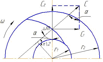
The absolute speed is equal to the vector
the sum of the carry speed Uare the speeds of rotation of the particle with the worker
wheel and relative speedWmovement along the scapula relative to
moving coordinate system associated
with spinning wheel.
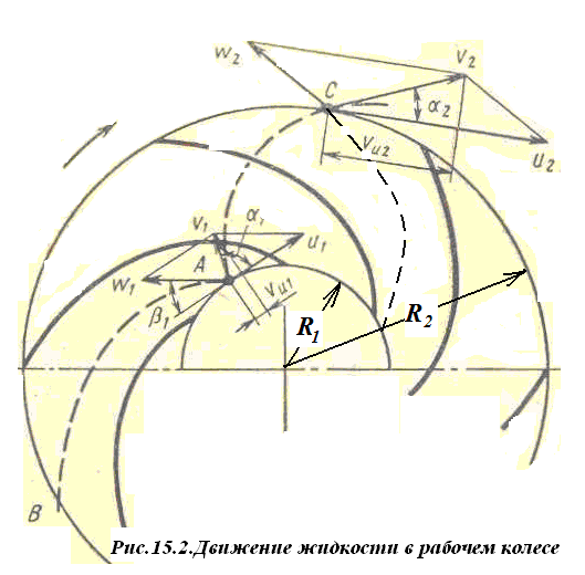
On fig. 15.2 dash-dot line
shows the trajectory of the particle from the entrance
and before leaving the pump in relative
movement - AB, trajectory of the portable
movements coincide with circles on
wheel radii, for example, on radii
R1and R2.
Trajectories of particles in absolute motion
from pump inlet to outlet - AC. Movement
mobile system - relative, in
mobile - portable.
Parallelograms of speeds for entry into
impeller and exit from it:
 (15.5)
where i= 1.2.
Relative speed sum Wand portableUwill give absolute speedV
.
Speed parallelograms in fig. 15.2
show that the angular momentum of the particle
fluid at the outlet of the impeller
more than input
V2Cosα2R2
> V1Cosα1R1
Therefore, when passing through
wheel moment of momentumincreases. Moment rise
the amount of motion caused by the moment
forces with which the impeller acts
to the liquid in it.
For a steady flow of fluid
momentum difference
fluid leaving the canal and entering
into it per unit of time is equal to the moment
external forces with which the impeller
acts on the liquid.
Moment of forces with which the impeller
acts on the liquid is:
M = Qρ(V2Cosα2R2
— V1Cosα1R1),
where Q is the flow rate
liquids through the impeller.
Multiply both sides of this equation by
impeller angular speed ω.
M ω= Qρ(V2Cosα2R2ω
— V1Cosα1R1ω),
Work Mωcalled
hydraulic power, or work
produced by the impeller in
unit of time, acting on
the liquid it contains.
From the Bernoulli equation, we know that
specific energy, transmitted
unit of weight of a liquid is called
pressure. In the Bernoulli equation, the source
energy to move the fluid
pressure difference.
When using the pump, the energy or
the pressure is transferred to the fluid by the workers
pump wheel.
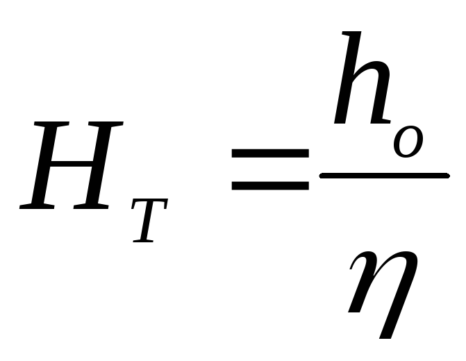
Theoretical impeller head
— HT called
specific energy, transmitted
unit weight of liquid impeller
pump.
N=Mω= HT*Qpg
Given that u1=R1ω
- portable (circumferential) speed
the impeller at the inlet andu2
= R2
ω - working speed
wheels at the output and that the projection of the vectors
absolute speeds per direction
portable speed (perpendicular
to radii R1 and R2)
equalVu2
=V2Cosα2
andVu1
= V1Cosα1,
whereVu2andVu1
, we get the theoretical head
as
HT*Qpg
= Qρ(V2Cosα2R2ω
— V1Cosα1R1ω),where
 (15.6)
Actual pump head
 less
less
theoretical pressure because it
real values of velocities are taken and
pressure.
Vane pumps are single stage
and multistage. In single stage
pumps fluid passes through the working
wheel once (see Fig. 15.1). pressure
such pumps at a given frequency
rotation is limited. To increase pressure
use multistage pumps
which there are several in succession
connected impellers fixed
on one shaft. Pump head rises
proportional to the number of wheels.
Vane pump can work with
different modes, i.e. at different feeds
and rotational speeds.
Covering the valve installed on
pressure pipe of the pump, reduce
feed. It also changes the pressure
developed by the pump. For operation
pump needs to know how it changes
head, efficiency and power consumed
pump, when its supply changes, i.e.
know the characteristics of the pump, under which
refers to the dependence of pressure, power
and efficiency of the pump from its supply at a constant
rotational speed (Fig. 15.3). 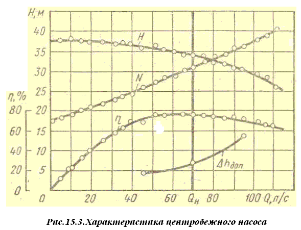
The mode of operation of the pump, in which it
Efficiency is at its maximum
is called optimal.
Basic installation errors
Let's take a look at the most common mistakes many of us make:
Suction pipe diameter. Quite often, the diameter of the pipeline in practice is less than the diameter of the suction pipe. This design, when connected, increases the resistance on the side of the suction line, thereby reducing the suction depth.In simple terms: a pipeline reduced in diameter is simply not able to pass the size of the liquid that the pump easily sucks in and pumps.
Direct connection to a regular hose. Such a system is not particularly critical if a pump of small capacity is used. Otherwise, under the influence of the high pressure created by the pump, the hose will shrink, its cross section will be significantly reduced, and water simply cannot pass through it. At best, this will lead to a cessation of the water supply, at worst, to a breakdown of the pump without the possibility of its subsequent repair.
A large number of bends and turns in the pipeline. This installation option does not increase the resistance value, respectively, reduces the performance and the pump head
That is why it is so important to reduce the number of bends and turns to a minimum value if you want to use the purchased and installed pump at 100%.
Sealing. It is due to insufficient sealing in the suction section of the pipeline that significant water losses can occur.
Poor sealing not only reduces the water pressure, but also accompanies the pump operation with excessive noise.
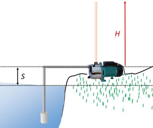
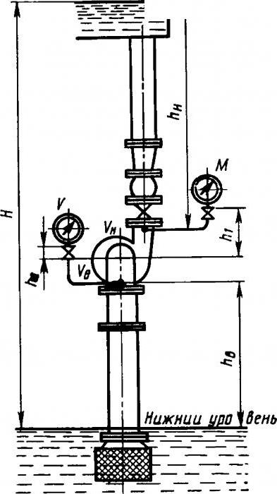
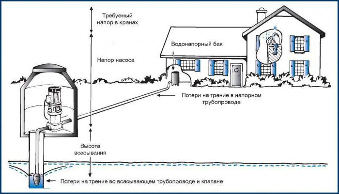
Submersible pump head
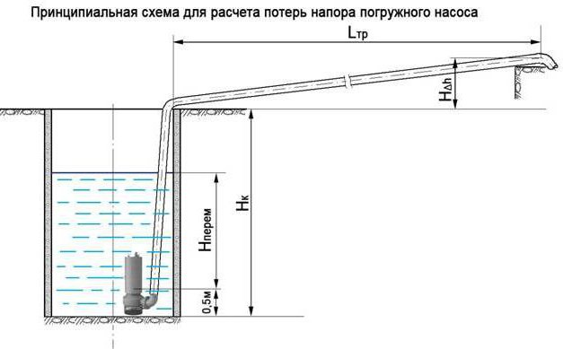
That is why one of the safest and most reliable is the submersible pump. Its pressure is calculated by the formula:
H = H height + H loss + H spout where:
H height - height difference between the location of the pump and the highest point of the water supply system;
H losses - possible hydraulic losses that occur when the fluid moves through the pipe, they are primarily associated with the friction of the fluid against the pipe walls;
H spout - the pressure on the spout that allows you to use all plumbing fixtures (usually in the range of 15-20 meters).
We have already established that the head of a pump is the pressure required to push a liquid to a given height. Circulation pumps have found themselves in heating systems, it is with their help that uninterrupted circulation of the heat source in the system is ensured
Of course, the choice of a circulation pump must be approached more consciously and demandingly, understanding that the efficiency and uninterrupted operation of its use largely depend on this, which is so important for apartment buildings. Such pumps are reliable, efficient and have proven themselves even in apartment buildings.
Of course, such a pump should also be selected based on the pressure. The pressure of the circulation pump has no connection, and, accordingly, dependence on the height of the building. The main thing here is the hydraulic resistance of the track. And here the following formula is required for the calculation:
H = (R * L + Z sum) / (p * g) where:
R - losses;
L is the length of the pipeline, measured in meters;
Z sum - the total number of safety factors for the structural elements of the pipeline (for fittings and fittings, this value is 1.3; for thermostatic valves - 1.7; and for mixers - 1.2);
p is the density of water, we remember from the school physics course that it is 1000 kg/m3;
g is the free fall acceleration, the value of which is taken as an average value - 9.8 m/s2.
It turns out that, knowing all the basic parameters, it is quite simple to determine the water pressure that you need in a particular situation, for this you do not have to involve specialists.
Why in meters
A pump for the pressure of water and any other liquid is a very popular device, without which it is difficult to imagine life in a private house. Many consumers still do not understand why the pressure is measured in meters.
The pressure of a centrifugal pump, however, like any other, is usually measured in meters. Of course, such a system raises many questions. First of all, it happened historically, everyone has long been accustomed to such a designation and does not intend to change anything.And, of course, it is convenient, because you do not have to resort to using other units of measurement, to perform complex mathematical calculations. The head value, calculated in meters, gives us information that the pump can lift the liquid to a given height.
Conclusion
"Hydraulics" on
a specific methodological example of calculation
volumetric hydraulic drive it is shown that
to select the required devices (pump,
hydraulic motors, hydraulic devices, filter,
working fluid conditioners, hydraulic lines
and their elements, electric motor) and
efficient operation of the hydraulic drive
need to calculate
Very
it is important not to make mistakes in calculations
and units of measurement, because on error
You can select a device that
during operation of the hydraulic drive
will not meet the requirements
applied to the unit as a whole.
The results of the work performed allow
make a conclusion about sufficient accuracy
performing calculations and choosing
hydraulic equipment