Aerodynamics of engineering networks
Network engineering
ventilation and heating of buildings
calculated according to the laws of aerodynamics.
It uses the Bernoulli equation
for gas (see p. 42), which includes
pressure, not force. Even water
heating is calculated according to
pressure, since it has a
fluid temperature change and
according to its density, so
applying pressure values is inconvenient.
Aerodynamic calculation of these networks
comes down to determining the current
pressure difference Dpetc
(causing movement in them), losses
pressure in them Dpsweat,
speeds, costs and geometric
dimensions of passage sections.
The calculation is carried out according to
Bernoulli's equation is so. Gotta pick up
such dimensions of pipelines, channels
and their passage sections (which
create resistance to flow)
flow rates were acceptable,
expenses met the norms and the difference
pressure Dpetc
was equal to the pressure loss in the network
Dpsweat,
moreover, for the safety margin, the losses
artificially increased by 10%.
Therefore, to calculate engineering
networks the Bernoulli equation is applied
in this entry:
Dpetc=1.1Dpsweat,
and the network finally
must satisfy this equality.
Difference Definition
pressure Dpetc
will be discussed below with examples.
calculations of a furnace with a chimney and
water heating with natural
circulation.
Pressure loss Dpsweat
in a pipeline, duct or
gas pipeline can be found by the formula
Weisbach
for gas:
 ,
,
where z
—
coefficient of hydraulic resistance,
same as for liquid (see p. 21),
only in case of non-circular section
must use the value
equivalent diameter duh
instead of d.
Total pressure loss Dpsweat
sum of linear Dpl
and localDpm
losses:
Dpsweat=
SDpl+
SDpm.
To calculate Dpl
and Dpm
the Weisbach formula for gas is applied,
in which instead of z
substitute accordingly zl
or zm
(see p. 23), but instead d
—
duh.
For example, when
definition of Dpl
linear hydraulic coefficient
resistance (dimensionless value)
zl
=
l
l/duh
,
where l
—
the length of the straight section of the network.
Hydraulic coefficient
friction l
in turbulent conditions (practically
always in gas flows) is determined
So:
 ,
,
where D
—
roughness of the pipeline walls or
channel, mm.
For example, ventilation ducts
sheet steel have D
= 0,1
mm, and air ducts
in a brick wall D
=
4
mm.
Coefficient values
local hydraulic resistance
zm
accepted according to reference data for
specific areas of deformation
flow (pipe entry and exit, turn,
tee, etc.).
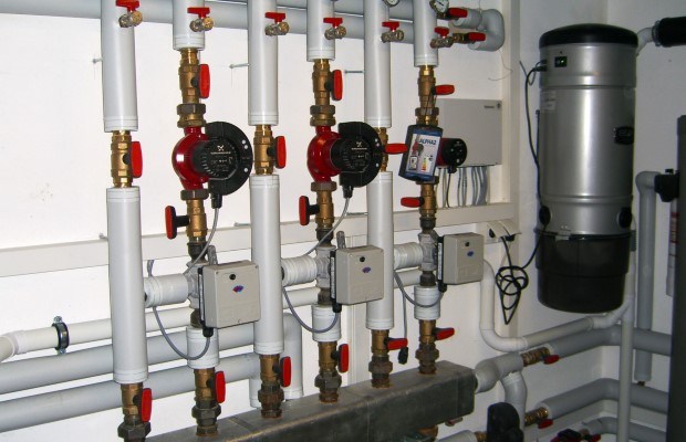
How to control system pressure
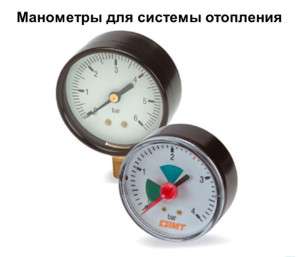 To control at various points in the heating system, pressure gauges are inserted, and (as mentioned above) they record excess pressure. As a rule, these are deformation devices with a Bredan tube. In the event that it is necessary to take into account that the pressure gauge must work not only for visual control, but also in the automation system, electrocontact or other types of sensors are used.
The tie-in points are defined by regulatory documents, but even if you have installed a small boiler for heating a private house that is not controlled by GosTekhnadzor, it is still advisable to use these rules, since they highlight the most important heating system points for pressure control.
It is imperative to embed pressure gauges through three-way valves, which ensure their purge, reset to zero and replacement without stopping all heating.
The control points are:
- Before and after the heating boiler;
- Before and after the circulation pumps;
- Output of heat networks from a heat generating plant (boiler house);
- Entering heating into the building;
- If a heating regulator is used, then the pressure gauges cut in before and after it;
- In the presence of mud collectors or filters, it is advisable to insert pressure gauges before and after them. Thus, it is easy to control their clogging, taking into account the fact that a serviceable element almost does not create a drop.
System with installed pressure gauges
A symptom of a malfunction or malfunction of the heating system is pressure surges. What do they stand for?
Small difference between upper and lower pressure
The low criterion is when the difference between the upper and lower pressure is 25% or less. So, the lower limit for the value of 120 is 30 units. The optimal level is 120-90 mm Hg. There are many reasons for the slight difference between upper and lower blood pressure.
The phenomenon often develops with:
- Vegetovascular dystonia.
- Aortic stenosis.
- Heart failure.
- Inflammation in the myocardium.
- Tachycardia.
- Left ventricular stroke.
State photos:
The disease is characterized by such manifestations - loss of consciousness, excessive irritability, aggression, apathy. There are also complaints about:
- Cephalgia.
- Drowsiness.
- Malaise.
- Dyspeptic disorders.
If this is not detected in a timely manner and measures are not taken, a small difference between the upper and lower pressure will sooner or later lead to the appearance of:
- Hypoxia.
- Cardiac arrest.
- Serious disorders in the brain.
Also, the phenomenon is fraught with respiratory paralysis, a significant deterioration in vision.
The disease is dangerous, and if you do not take action, it will constantly increase, it will be difficult to treat it. It is necessary to monitor the upper and lower blood pressure, calculate the gap between the values. This is the only way to help yourself or a relative in time, as well as to prevent unpleasant complications.
Recommended for viewing:
—
CAUTION 1
|
Ð Ð Ð Ð Ð Ð Ð Ð Ð Ð Ð Ð Ð Ð Ð Ð Ð Ð Ð Ð Ð Ð Ð Ð Ð Ð Ðμ Ð Ð Ð Ð Ðμ Ð Ð Ð Ð ÐμÐ Ð Ð Ð Ð Ð Ðμ ÑÑжаÑÑего ÑÑÑÑойÑÑва в ÑÑÑбопÑоводе. a |
азноÑÑÑдавлений - ñ - 2 ñ ð ð ð ñ Ð Ð Ð Ð Ð Ð Ð Ð Ð Ð Ð Ð Ð Ð Ð Ð Ð Ð Ð Ð Ð Ð Ð Ð Ð Ð Ð Ð Ð Ð Ð Ð Ð Ð Ð Ð Ð ² Ð Ð Ð Ð Ð Ð ² Ð Ð Ð Ð Ð Ð Ð ´.
a
|
Ð ¡¡ñμºð Ð Ð Ð Ð Ð Ð Ð Ð Ð Ð Ð Ð Ð Ð Ð Ð Ð Ð Ðμ ñ Ð Ð Ðμl a |
азноÑÑÑдавлений (PI - PZ) R) Ð Ð · SHUTTER. Ð Ð ÐμÐ Ð Ð Ð Ð Ð Ð Ð Ð Ð Ð Ð Ð Ð Ð Ð Ð Ð Ð Ð Ð Ð Ð Ð Ð Ð Ð Ð Ð Ð Ð Ð Ð Ð Ð Ðμ 0 5 до 5 мкм. ÐнÐμвмР° ÑиÑÐμÑкиÐμ пÑиР± оÑÑ Ð¿Ð¾Ð · воР»ÑÑÑ Ð¾ÑÑÑÐμÑÑвл ÑÑÑ Ð'иÑÑÐ ° нÑионнÑй конÑÑоР»Ñ, Ð ° в ÑоÑÐμÑÐ ° нии Ñ Ð¼ÐμÑÐ ° - ноÑÐ »ÐμкÑÑиÑÐμÑкими иР· мÐμÑиÑÐμл ÑнÑми пÑÐμоР± ÑÐ ° Ð · овР° ÑÐμÐ »Ñми Ð ° вÑомР° ÑиР· иÑовР° ÑÑ Ð¿ÑоÑÐμÑÑ ÑÐμги ÑÑÑÐ °Ñии
a
азноÑÑÑдавлений, Ð Ð Ð Ð Ð Ð Ð Ð Ð Ð Ð Ð Ð Ð Ð Ð Ð Ð Ð Ð Ð Ð Ð Ð Ð Ð Ð Ð Ð Ð Ð Ð Ð Ð Ð Ð Ð Ð Ð Ð Ð Ð Ð Ð Ð Ð Ð Ð Ð Ð Ð Ð Ð Ð Ð Ð Ð Ð Ð Ð Ð Ð Ð Ð Ð Ð Ð Ð Ð Ð
a
азноÑÑÑдавлений Ð Ð Ð Ð Ð Ð Ð Ð Ð Ð Ð Ð Ð Ð Ð Ð Ð Ð Ðμ Ð Ð Ð Ð Ð Ð Ð Ð Ð Ð Ð Ð Ð Ð Ð Ð Ð Ð Ð Ð Ð Ð Ð Ð Ð Ð Ð Ð Ð Ð Ð Ð Ð Ð Ð Ð Ð Ð Ð Ð Ð Ð Ð Ð Ð Ð Ð Ð Ð Ð Ð Ð Ð Ð Ð Ð ñ
a
азноÑÑÑдавлений, иР· мÐμÑÑÐμмР° Ñ Ð¿ÑиР± оÑом, ÑÑÐ ° вновÐμÑивР° ÐμÑÑÑ Ð²ÐμÑом ÑÑоР»Ð ± Ð ° ÑÑÑÑи и опÑÐμÐ'Ðμл ÑÐμÑÑÑ ÑÐ ° Ð · ноÑÑÑÑ ÐμÐμ ÑÑовнÐμй в мР¸Ð½ÑÑовом
a
азноÑÑÑ Ð´Ð°Ð²Ð»ÐµÐ½Ð¸Ñ Ð'оÑÑигР° ÐμÑ Ð¼Ð ° кÑимÑмР° пÑи ÑÐ ° Ð ± оÑÐμ ÑÐμÑÑÑÐμÑ Ð ± Ð »Ð¾ÐºÐ¾Ð² нР° номинР° л Ñной нР° гÑÑÐ · кÐμ 24 кР/ м2 нР° оÑмÐμÑкÐμ 168 Ð Ð Ð Ð Ð Ð Ð Ð Ð Ð Ð Ð Ðμ Ð Ð Ð Ð Ð Ð Ð Ð Ð Ð Ð Ð Ð Ð Ð Ð Ð Ð Ð Ð Ð Ð Ð Ð Ð Ð Ð Ð Ð Ð Ð Ð Ð Ð Ð Ð Ð Ð Ð Ð Ð Ð Ð Ð Ð Ð Ð Ð Ð Ð Ð Ð Ð ²ñðÐðо¾¾¾ðð𺺺ººðº¾ðμºðððμμμμμ SESSION±S. Ð Ð °Ð ° Ð ± Ð Ð Ð Ð Ð Ð Ð Ð Ð Ð Ð Ð Ð Ð Ð Ð Ð Ð Ð Ð Ð δÐ Ð Ð δ Ðμ Ðμ Ð μm Ð Ðμ Ð μm Ð Ð Ð μm Ð Ðμññ Ð · Ðμñð¶μ Ð ·
a
|
C. Сñ¼μμμμº²² Ð Ð Ð Ð Ð Ð Ð Ð Ð Ð Ð Ð Ð Ð Ð Ð Ð Ð Ð Ð Ðμ Ñлое. a |
азноÑÑÑдавлений Ñ — измеÑÑÑÑ Ñ ¿Ð¾Ð¼Ð¾ÑÑÑ Ð´Ð¸ÑÑеÑенÑиалÑнÑÑ Ð¿Ð¾Ð¼Ð¾ÑÑÑ Ð´Ð¸ÑÑеÑенÑиалÑнÑÑ Ð¿Ð¾Ð¼Ð¾ÑÑÑ
a
|
| Ð Ð Ð Ð Ð Ð Ð Ð Ð Ð Ð Ð Ð Ð Ð Ð Ð Ð · C. a |
азноÑÑÑдавлений 10.0000000000000000000000001 Ð Ð Ð Ð Ð Ð Ð Ð Ð ÐμÐ Ð Ð Ð Ð ÐμÐ Ð Ð ÐμÐ Ð ÐμÐ'Ð Ð Ð ÐμññÐ Ð Ð Ð Ðμññ Ð Ð Ð Ð μm Ð Ð Ð Ð Ð μm Ð Ð Ð Ð Ð μm Ð Ð Ð Ð Ð μm Ð Ð Ð Ð Ð μm Ð Ð Ð Ð Ðμ
a
азноÑÑÑдавлений Ð Ð Ð Ð Ð Ð Ð Ð Ð Ð μm Ð Ð Ð Ð Ð Ð Ð Ð Ð Ð Ð Ð
a
Pressure
The diagonal type of connection is also called the side cross scheme, because the water supply is connected from above the radiator, and the return line is organized at the bottom of the opposite side. It is advisable to use it when connecting a significant number of sections - with a small number, the pressure in the heating system rises sharply, which can lead to undesirable results, that is, heat transfer can be halved.
To finally stop at one of the connection options, you must be guided by the methodology for organizing the return. It can be of the following types: single-pipe, two-pipe and hybrid.
Which option is worth stopping at will directly depend on a combination of factors. It is necessary to take into account the number of storeys of the building where the heating is connected, the requirements for the price equivalent of the heating system, what type of circulation is used in the coolant, the parameters of the radiator batteries, their dimensions, and much more.
Most often, they stop their choice precisely on a single-pipe wiring diagram for heating pipes.
Such a system has a number of characteristics: they are low cost, easy to install, the coolant (hot water) is supplied from above when choosing a vertical heating system.
Also, they are connected to the heating system in series, and this, in turn, does not require a separate riser for organizing the return. In other words, water, having passed the first radiator, flows into the next, then into the third, and so on.
However, there is no way to regulate the uniform heating of radiator batteries and its intensity, they constantly record a high pressure of the coolant. The farther the radiator is installed from the boiler, the more heat transfer decreases.
There is also another wiring method - a 2-pipe scheme, that is, a heating system with a return. It is most often used in luxury housing or in an individual home.
With hybrid wiring, the two schemes described above are combined. This may be a collector circuit, where an individual wiring branch is organized at each level.
- Although ordinary people believe that they do not need to know exactly what scheme the heating of an apartment building is equipped with, situations in life can really be different. For example,…
- The choice of which coolant to buy for a heating system depends on the conditions of its operation. The type of boiler and pumping equipment, heat exchangers, etc. is also taken into account.
Heating was invented to ensure that the buildings were warm, there was a uniform heating of the room. At the same time, the design that provides heat should be easy to operate and repair. A heating system is a set of parts and equipment used to heat a room. It consists:
- A source that creates warmth.
- Pipelines (supply and return).
- heating elements.
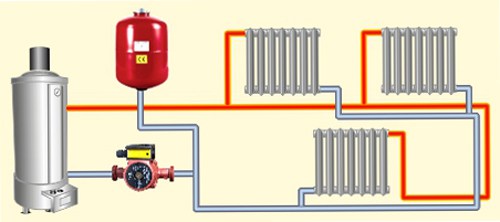
Heat is distributed from the starting point of its creation to the heating block with the help of a coolant. It can be: water, air, steam, antifreeze, etc. The most used liquid coolants, that is, water systems. They are practical, since various types of fuel are used to create heat, they are also able to solve the problem of heating various buildings, because there are really many heating schemes that differ in properties and cost. They also have high operational safety, productivity and optimal use of all equipment as a whole. But no matter how complex heating systems would be, they are united by the same principle of operation.
Heating system
Why do you need an expansion tank
Accommodates excess expanded coolant when it is heated. Without an expansion tank, the pressure can exceed the tensile strength of the pipe. The tank consists of a steel barrel and a rubber membrane that separates air from water.
Air, unlike liquids, is highly compressible; with an increase in the volume of the coolant by 5%, the pressure in the circuit due to the air tank will increase slightly.
The volume of the tank is usually taken to be approximately equal to 10% of the total volume of the heating system. The price of this device is low, so the purchase will not be ruinous.
Proper installation of the tank - eyeliner up. Then no more air will get into it.
Why does pressure decrease in a closed circuit?
Why does pressure drop in a closed heating system?
After all, the water has nowhere to go!
- If there are automatic air vents in the system, the air dissolved in the water at the time of filling will exit through them.
Yes, it is a small part of the coolant volume; but after all, a large change in volume is not necessary for the pressure gauge to note the changes. - Plastic and metal-plastic pipes can be slightly deformed under the influence of pressure. In combination with high water temperature, this process will accelerate.
- In the heating system, the pressure drops when the temperature of the coolant decreases. Thermal expansion, remember?
- Finally, minor leaks are easy to see only in centralized heating by rusty traces. The water in a closed circuit is not so rich in iron, and the pipes in a private house are most often not steel; therefore, it is almost impossible to see traces of small leaks if the water has time to evaporate.
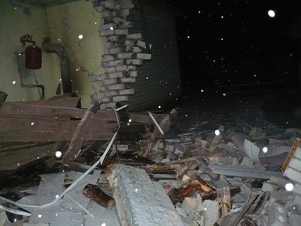
What is the danger of a pressure drop in a closed circuit
Boiler failure. In older models without thermal control - up to the explosion. In modern older models, there is often automatic control of not only temperature, but also pressure: when it falls below the threshold value, the boiler reports a problem.
In any case, it is better to maintain the pressure in the circuit at about one and a half atmospheres.
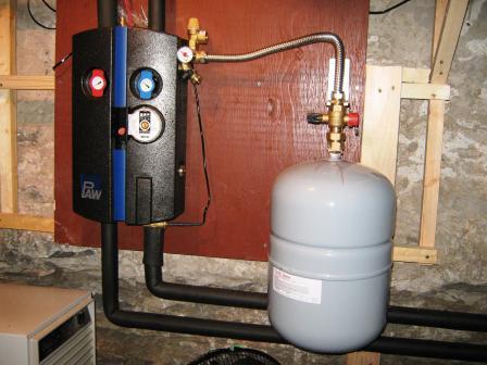
How to slow down the pressure drop
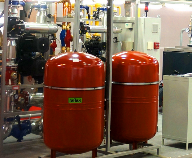
In order not to feed the heating system over and over again every day, a simple measure will help: put a second larger expansion tank.
The internal volumes of several tanks are summarized; the greater the total amount of air in them, the smaller the pressure drop will cause a decrease in the volume of the coolant by, say, 10 milliliters per day.
Where to put the expansion tank
In general, there is no big difference for a membrane tank: it can be connected to any part of the circuit.Manufacturers, however, recommend connecting it where the water flow is as close to laminar as possible. If there is a tank in the system, it can be mounted on a straight pipe section in front of it.
Prevention of drops in the heating system
Timely execution of routine inspections and work will prevent the appearance of pressure drops in the heating pipes of a multi-storey building.
The set of activities is as follows:
- installation of a safety valve on the equipment to relieve excess pressure;
- checking the pressure behind the diffuser of the expansion tank and pumping water if the pressure of the tank does not correspond to the design norm - 1.5 atm;
- washing filters that retain dirt, rust, scale.
Monitoring the good condition of shut-off and control valves is represented by the same prerequisite.
1. General information
fluid consumption,
gas, steam, water, coolant, oil,
gasoline, milk, etc. entering the
working channels are measured in technological
processes, as well as in accounting operations.
Instruments that measure
flow are called flowmeters.
Consumption
substance is the amount of substance
passing per unit of time
pipeline, channel, etc.
Substance consumption
expressed in volume or mass units
measurements.
Volume units
flow rate: l/h, m3/s,
m3/h
Mass units
flow rate: kg/s; kg/h, t/h.
The transition from bulk
units of flow to mass and vice versa
produced by the formula:
Qm
= Qabout
p,
where p
— substance density, kg/m3;
Qm
—mass
consumption, kg/h;
Qabout
— volume flow, m3/h.
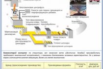
Most often
flow measurement method applied
by variable pressure drop across
narrowing device installed in
pipeline.
Operating principle
variable differential flowmeter
based on a change in potential
energy of the measured substance at
flow through an artificially narrowed
section of the pipeline.
According to the law
energy saving full mechanical
energy Wfull
flowing
substances, which is the sum
potential energy Wsweat
(pressure)
and kinetic Wkin
(speed) in the absence of friction is
constant value i.e.
Wfull
= Wsweat+
Wkin
= const
Thus, at
medium flow through a narrowed section
there is a partial transition of the potential
energy into kinetic energy. Due
with this static pressure in
betrothed
cross section will be less than the pressure before
place of constriction. Pressure difference before
narrowed area and in the place of narrowing,
called pressure drop,
more, the more speed (flow)
flowing substance. By drop
it is possible to determine the amount of consumption
flowing environment.
The nature of the flow
and pressure distribution P
in pipeline 1
with restrictor 2
shown in Figure 3.1.
Compression
flow begins in front of the diaphragm and
reaches its maximum value
some distance behind it (due to
inertia forces). Then the flow expands
to the full section of the pipeline. Front
diaphragm and behind it vortexes are formed
zones (turbulent flows).
Rice.
3.1. Flow pattern and distribution
pressure
v
pipeline with a restrictor
In front of the diaphragm
due to flow deceleration,
pressure jump P1
R1.
Lowest pressure - Pʹ2
on some
distance behind the diaphragm. By
expansion
pressure
at the walls
increases
but
does not reach
former
values
due to
losses
energy
to the formation of vortex flows. Difference
RP
called irretrievable loss
pressure. Thus, when flowing
substances through a constriction device
(SU) creates a pressure drop Р
= P1
— P2
, depending
on the flow rate and therefore
fluid flow. Hence it follows that
differential pressure created by the narrowing
device that can serve as a measure of consumption
material flowing through the pipeline
and the numerical value of the substance consumption
can be determined from the difference
pressure ΔР, measured by a differential pressure gauge.
The ratio between
these quantities for liquid, gas and
the pair is given by the simplified equation
 (m3/h),
where To1—
constant ratio.
Pressure drop
on the narrowing device is determined with
using means of measuring the differential
pressure (differential pressure gauges
- differential pressure gauges) of any type by
connecting them through connecting
pipes to the pressure ports.
Can be connected to one
narrowing device of two or more
differential pressure gauges.
When determining
relationship between flow and differential
assume the following conditions:
flow
steady-state (before and after SS - direct
sections of the pipeline);
-
flow
completely fills the pipeline; -
Wednesday
single-phase and does not change the phase
condition; -
front
SU does not accumulate condensate, etc.; -
channel
has a specific profile (usually
round section).
Heating system of an apartment building
In accordance with the requirements of GOST and SNIP, the heating systems of an apartment building must provide air heating in residential premises in winter to a temperature of 20-22 degrees at a humidity of 45-30%. To do this, when developing design estimates for construction, the heating system of an apartment building is also designed, providing the same coolant pressure in the pipes, both on the first and and top floors building. Only under this condition is it possible to ensure the normal circulation of the coolant, and, consequently, the required parameters of the air in the room.
Heating systems of an apartment building
If you look closely at the scheme of the heating system of an apartment building, you can see that the diameter of the pipelines that deliver the coolant to each dwelling is steadily decreasing. For example, the in-house heating system of an apartment building in the basement has a pipeline diameter of 100 mm at the inlet, "beds" that distribute the coolant along the entrances # 8211 76-50 mm, depending on the size of the building and the length of the wing, and pipes with a diameter of 20 are used for the installation of risers mm. On the return line, this rule works in reverse order in ascending order.
It is necessary to dwell on the design features of the sunbeds, the heating system of multi-apartment residential buildings (on the supply and return lines). Their limit switches are plugged with a ball valve with a diameter of 32 mm, installed at a distance of at least 30 cm from the last riser. It is done in order to create an accumulation pocket for scale, scale and other contaminants accumulated in the lower, horizontal part of the system, which are removed during a scheduled flushing of the heating system.
However, the adjustment of the heating system of an apartment building, described above, does not allow flexible pressure equalization in the system, which leads to a decrease in the temperature of the rooms on the upper floors, and in rooms whose heating is mounted on the return. This problem is well dealt with by the hydraulics of the heating system of an apartment building, which includes circulation vacuum pumps and an automated pressure control system that are mounted in the manifold on each floor of the building. In this case, the scheme for disassembling the coolant by floors changes and additional space is required for its installation, which is the reason for the rare use of hydraulics in the heating system of an apartment building.
The device of the heating system what is the return
The heating system consists of an expansion tank, batteries, and a heating boiler.All components are interconnected in a circuit. A fluid is poured into the system - a coolant. The fluid used is water or antifreeze. If the installation is done correctly, the liquid is heated in the boiler and begins to rise through the pipes. When heated, the liquid increases in volume, the excess enters the expansion tank.
Since the heating system is completely filled with liquid, the hot coolant displaces the cold one, which returns to the boiler, where it heats up. Gradually, the temperature of the coolant increases to the required temperature, heating the radiators. The circulation of the liquid can be natural, called gravity, and forced - with the help of a pump.
Batteries can be connected in three ways:
- 1.
Bottom connection. - 2.
diagonal connection. - 3.
Side connection.
In the first method, the coolant is supplied and the return is removed at the bottom of the battery. This method is advisable to use when the pipeline is located under the floor or baseboards. With a diagonal connection, the coolant is supplied from above, the return is discharged from the opposite side from below. This connection is best used for batteries with a large number of sections. The most popular way is side connection. Hot liquid is connected from above, the return flow is carried out from the bottom of the radiator on the same side where the coolant is supplied.
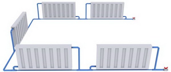
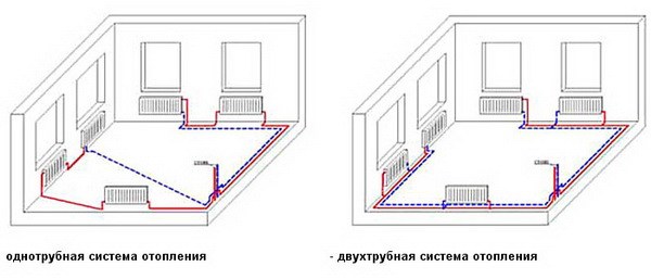
Heating systems differ in the way pipes are laid. They can be laid in one-pipe and two-pipe way. The most popular is the single-pipe wiring diagram. Most often it is installed in multi-storey buildings. It has the following advantages:
- a small number of pipes;
- low cost;
- ease of installation;
- serial connection of radiators does not require the organization of a separate riser for draining liquid.
The disadvantages include the inability to adjust the intensity and heating for a separate radiator, the decrease in the temperature of the coolant as it moves away from the heating boiler. To increase the efficiency of single-pipe wiring, circular pumps are installed.
For the organization of individual heating, a two-pipe piping scheme is used. Hot feed is carried out through one pipe. On the second, the cooled water or antifreeze is returned to the boiler. This scheme makes it possible to connect radiators in parallel, ensuring uniform heating of all devices. In addition, the two-pipe circuit allows you to adjust the heating temperature of each heater separately. The disadvantage is the complexity of installation and the high consumption of materials.