Control valve.
This valve is similar to a pressure reducing valve. The control valve has a special actuator, usually pneumatic or electric, connected to an automatic regulator. The control unit is a device that measures fluid flow, temperature or pressure and compares them to the desired level. The control unit issues a command that sets the desired position of the working body. The movement of the working body in control valves can be translational or rotational; Structurally, they are most often valve or throttle type. Control valves are widely used to control the pressure or flow of a liquid. Such a valve is rarely fully closed or open. In the control valve, the flow is throttled, which is accompanied by a pressure drop. In this regard, such a valve must have a high resistance to the erosive action of the fluid flow. The pressure drop can lead to cavitation in liquids and noise in gas or vapor flows (cm. CAVITATION). Special designs of control valves with increased cavitation resistance and reduced noise have been developed. Control valves operate under more adverse conditions than most other valve types.
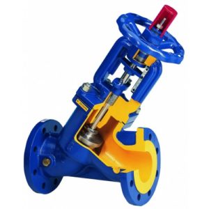
Drainage safety valves.
Safety and drain valves are devices for automatically reducing pressure in closed vessels when it reaches a dangerous limit. These valves are used in a wide variety of technical devices from coffee makers, pressure cookers and boiler heating systems to power plants, where the pressure reaches 30 MPa, and power hydraulic systems, in which the pressure can reach 70 MPa. There is a certain difference between safety and drain valves. A safety valve is a special type of spring-loaded drain valve that is designed to open momentarily to release a large amount of steam or gas at once, and then abruptly close again. Drain valves are used to vent to the atmosphere in liquid systems, and safety valves in high pressure gas and steam systems.
The drain valve opens slightly when the pressure in the vessel reaches a set (low) value, and slowly increases the release of liquid as the pressure increases. The drain valve is usually used where it is undesirable or not necessary to release large volumes of the working fluid.
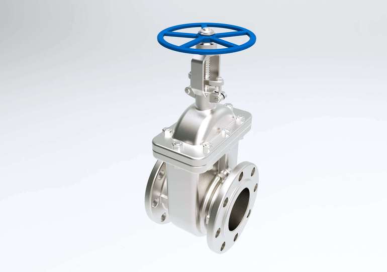
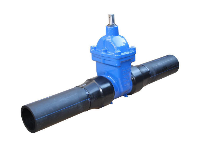
Gate valve.
Gate valves are commonly used in industrial piping systems where the valve must either be fully closed or fully open. Such a valve is called a check valve. When the valve is open, the flow passes almost unopposed. In the gates, the damper is lowered in the guides. In double-seated gate valves with a wedge, the discs are pressed against the seats due to their wedging when the stem moves. In valves with stem rotation, the lower end of the stem is screwed into the damper; the rotation of the stem raises and lowers the damper. Rising-stem valves, which take up more space in the open position, have a threaded top of the stem and a nut with thrust washers on the handwheel. The nut moves the stem when the handwheel is turned.
Valve Selection Recommendations
Due to the fact that flanged valves are widespread, their selection should be approached very carefully and scrupulously. If the device is chosen incorrectly, there is a possibility that it will soon fail. When buying a tool, there are several key parameters to consider:
- the material from which the body is made;
- type of shell;
- type of drive mechanism.
Valves, the body of which is made of steel, are durable and durable, but it is recommended to install them on pipelines through which steam, gas, oil products or water are transported. The advantage of alloy steel is that it is able to withstand low ambient temperatures, reaching 60 degrees below zero.
Valves made of stainless steel have high resistance to corrosion, as well as resistance to aggressive chemical elements. Flanged valves made of stainless steel are widely used in the food industry, because here it is necessary to maintain a high purity of the medium that is transported through the pipeline. Cast iron parts have low resistance to environmental factors, and they are also fragile and have a solid specific gravity. It is recommended to install such mechanisms on water supply systems.
When buying a shut-off valve, you need to consider the design of its body, which can be all-welded or collapsible. The size of the part and the ability to carry out one or another type of repair work will depend on the design. All-welded spare parts have a one-piece body that does not provide for the possibility of carrying out revision measures, therefore, such a valve should be installed in those areas where regulation of the medium flow is extremely rare
This precaution is necessary in order to prolong the life of the device.
The design of collapsible valves consists of separate parts, which, if necessary, can be replaced if any of them become unusable. It is precisely due to the fact that the valve is disassembled that it can be used to carry out any type of repair work, but such a tool is very expensive.
Depending on the specifics of the process, it is possible to choose a flanged valve with a suitable control mechanism. The simplest drive mechanism for flanged valves is the handle, with which the valve is transferred to open or closed mode. When choosing a valve for regulating the flow of thick substances, it should be borne in mind that the handle must be strong and made of durable materials.
Another common type of drive mechanism is a gearbox, which must be installed on pipes if their cross section is more than 300 mm. The rod is driven by a flywheel, which begins to rotate when the toggle switch is switched. Automatic devices are represented by pneumatic and electric control systems, with which you can control the valve even at a distance. Such devices contribute to the most efficient regulation of all technical processes.
Safety devices for pneumatic actuators
Multi-circuit brake actuators are characterized by the autonomy of each circuit, which manifests itself in the preservation of their performance in case of depressurization or failure of one or more circuits included in the drive.
In pneumatic multi-circuit drives, the autonomy of the circuits is carried out by means of protective valves - triple, double and single.
***
Double safety valve
The double protective valve (Fig. 1, a) serves to distribute the compressed air coming from the compressor over two circuits and maintain pressure in one circuit if the other is damaged. Compressed air from the compressor, having passed the pressure regulator and the anti-freeze protection, enters the central cavity and, having squeezed out two flat valves, passes through the outlet into the circuit of the auxiliary brake system, and at the same time, through the other outlet - into the circuit of the parking and spare systems of the tractor and trailer.
If an air leak occurs in one of the circuits, for example, connected to the right outlet, then the central piston, together with the right reed valve, will move to the right under the action of air pressure in the left outlet and press against the stop piston (the valve remains closed).
As soon as the pressure in the central cavity is greater than the force of the spring of the first thrust piston, the right plate valve will move away from the central piston and excess air will escape into the leaky circuit.
The same will happen in case of increased air flow in one of the circuits. If one of the circuits is damaged, the double protective valve maintains a pressure of 0.52 ... 0.54 MPa in the other circuit.
***
Triple safety valve
The triple safety valve (Fig. 1, c) distributes the air coming from the compressor into three autonomous circuits and, if one of them is damaged, maintains pressure in the healthy circuits.

Compressed air from the compressor enters the left and right cavities and, when the pressure rises to 0.52 MPa, opens the left and right valves, overcoming the resistance of its springs. By bending the left and right membranes, compressed air enters through the outlets into the circuits of the working brake mechanisms of the wheels of the front axle and trailer, as well as the wheels of the rear bogie and trailer.
At the same time, compressed air opens the left and right bypass valves, enters the central cavity and, at a pressure of 0.51 MPa, opens the central valve and passes through the outlet to the release circuit.
If one of the circuits is depressurized, the pressure in the cavity of the protective valve associated with it will decrease and, under the action of the spring, the valve of the damaged circuit will close.
If the supply line coming from the compressor is depressurized, then all valves will close under the action of their springs and the pressure in them will remain in the circuits.
***
Single safety valve
A single safety valve (Fig. 2) is used to connect the two circuits of the brake system and ensure their independent operation. Its function is to maintain pressure in the tractor receiver in case of an emergency pressure drop in the trailer line, and to protect the trailer from spontaneous braking in the event of a sudden pressure drop in the tractor receiver.

At a pressure of 0.55 MPa, compressed air entering through the inlet channel, overcoming the resistance of the piston return spring, lifts the membrane and passes into the outlet channel, and from there through the check valve enters the trailer supply line.
When the pressure in the inlet channel drops below 0.545 MPa, the piston return spring returns the membrane to its place. The non-return valve does not allow compressed air from the supply line to enter the outlet channel under the membrane.
***
Academic disciplines
- Engineering graphics
- MDK.01.01. "Car device"
- Section map
- General device of the car
- car engine
- car transmission
- Steering
- Brake system
- Suspension
- wheels
- Body
- Vehicle electrical equipment
- Fundamentals of car theory
- Fundamentals of technical diagnostics
- Fundamentals of hydraulics and heat engineering
- Metrology and standardization
- Agreecultural machines. Agreecultural equipment
- Basics of agronomy
- Transportation of dangerous goods
- Materials Science
- Management
- Technical mechanics
- Tips for a graduate student
Olympics and tests
- "Engineering graphics"
- "Technical Mechanics"
- "Engine and its systems"
- "car chassis"
- "Electrical equipment of the car"
Materials.
Valves are made of various materials: gray cast iron or ductile iron, bronze, carbon steel or stainless steel, and nickel-based alloys such as monel and inconel. These materials vary in cost, operating temperature range, and corrosion resistance and are listed in ascending order of cost.Gray cast iron is suitable for most non-critical applications, especially in plumbing. Bronze has high corrosion resistance and is used for corrosive environments. Carbon steel is strong and can be used at high pressures. Chrome-molybdenum steel is heat-resistant and is used at high temperatures (about 600 ° C), for example, in heating plants. Stainless steel and nickel alloys have higher corrosion resistance than bronze and high heat resistance. CORROSION OF METALS; METAL MECHANICAL PROPERTIES.
Valves made of these materials are used at pressures from less than 0.5 MPa (urban water supply systems) to 70 MPa (hydraulic actuators). The operating temperature can vary from 255°C (liquid hydrogen) to 800°C (gas turbines). Cheap materials such as gray cast iron are sometimes coated with epoxy to resist corrosion.
The internal parts of the valve can be made from the same materials as the body, but plastics, rubber and hard coatings are also used. As sealing materials sealing the seat, stem and valve, cotton, teflon, rubber or graphite are usually used, depending on the type of working medium and temperature. Sealing materials must provide good sealing and at the same time low friction to ensure free movement of the stem.
DRIVES
Valves usually have some kind of actuator. The simplest actuator is a linear valve handwheel or rotary lever. Special devices, such as a gear train, can be used to rotate the handwheel. Power hydraulic or pneumatic actuators are often used. These actuators can generate the significant forces required to move valves in high pressure systems or in remote locations, or to operate multiple valves from a single console. Spring operated diaphragm valve actuators typically use compressed air. Compressed air moves the diaphragm with the stem in one direction, and the spring in the opposite direction. Electric motors are also often used as drives. see also SERVO; AUTOMATIC CONTROL AND REGULATION.
Podlesny N.I., Rubanov V.G. Elements of the automatic control and monitoring system. Kyiv, 1982
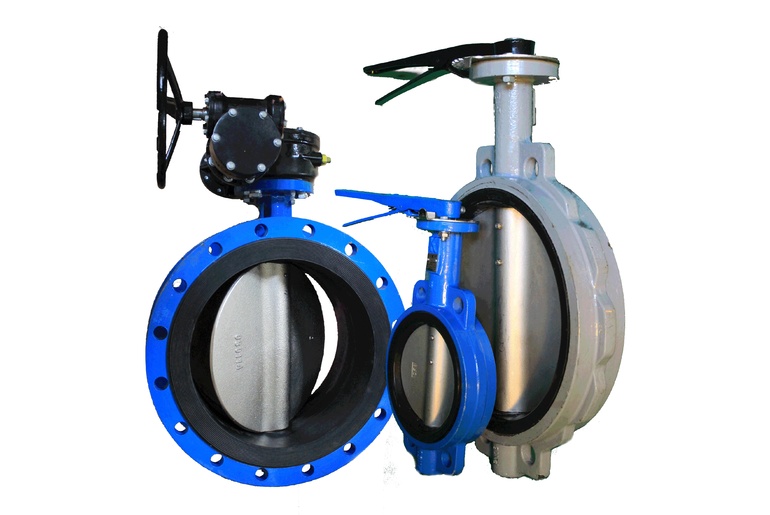
 Valves are designs of pipeline fittings with a shutter in the form of a flat or conical plate, moving reciprocating along the central axis of the sealing surface of the body seat. Valves also include valve structures (rotary valves), in which the valve in the form of a plate moves in an arc. The arc described by the valve center is tangent to the seat axis, the arc center is outside the seat hole, and the valve rotation axis is perpendicular to the medium flow axis.
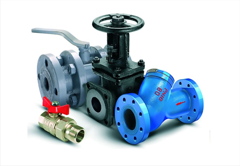
Popular Flanged Valve Models
Today, there are several varieties of shut-off valves. It all depends on what method is used to override the working environment. The list of popular models includes the following mechanisms:
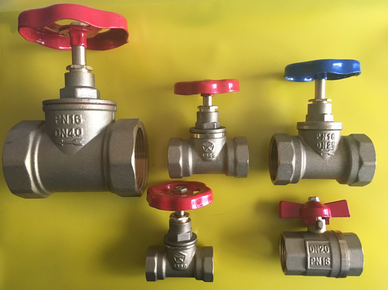
- screw;
- gate;
- ball;
- cork.
For screw parts, the movable valve is fastened with a threaded connection. It must be pressed against the seat, which is located in the main cylinder of the valve. The gland packing is represented by a sealing washer, which ensures the tightness of the device.
The specific disadvantages of the mechanism include the fact that it passes water in only one direction, and its rubber or paronite tubes periodically wear out and need to be changed. If sand or scale enters the cylinder, the gaskets can be completely or partially destroyed.
The design of gate valves is very similar to a gate valve, since their threaded stem allows the cone valve to be lowered between two mirrors.Instead of gland packing, rubber or polymer clay seals can be installed, which differ in their service life over a long period of time.
For the manufacture of ball flange fittings, brass or stainless steel is used, and the design is a ball with through holes. Turning the handle ensures rotation of the ball located in the valve cylinder, and its fixation is carried out using a pair of annular seats made of Teflon or fluoroplastic. For sealing it is recommended to use the same material.
The flow of liquid in plug flanged valves is blocked by means of a conical plug equipped with a through hole. Typical problems with such devices include the fact that the gland packing must be changed periodically.