VII. INSTALLATION INSTRUCTIONS
48. Installation and acceptance of RV and connections to it are carried out in accordance with SNiP III-28-75.
49. RV is installed at the entrance doors of the vestibule or stairwell.
50. When installing RV from cast-iron finned tubes or sections of heaters, it is necessary to ensure a tight fit of the casing guards to the fins of the heating element, excluding the passage of air past it.
51. When installing RV from heaters, the latter is installed horizontally, and the casing is attached to the flanges of the heater.
52. The air outlet in the RV should have a cross section 1.4 times larger than the active section of the heating element and be covered with a metal mesh with 10 × 10 mm cells or a decorative grille.
53. Shut-off and drain valves are installed on the supply and return pipelines of the supply lines to the RV.
54. In case of partial passage of water through the RV, on the jumper of the connections to it, it is installed between the flanges of the diaphragm valve, the diameter of the hole of which is determined by calculation.
55. On the supply pipeline of the heating network, after connecting the return pipeline from the RW, it is necessary to install a thermometer in a sleeve and a pressure gauge.
56. After mounting the RV and connections to it, it is necessary to perform a hydraulic pressure test of 10 kgf / cm2.
III. CALCULATION OF RW WITH A HEATING ELEMENT FROM CAST IRON RIBBED TUBES
13. Pig-iron ribbed tubes according to GOST 1816-76 can be used as heating elements of RV.
14. Finned tubes in the RV are installed horizontally in two or three rows along the air flow. The stiffeners must be in a vertical position.
15. To increase the speed of movement of the coolant inside the pipes, inserts from pipes with a diameter of 63.5 × 2.5 mm are installed.
16. The required heating surface of finned tubes RV is determined by the formula
|
(1) |
where Qrv — thermal load РВ, kcal/h; TO — heat transfer coefficient, kcal/(m2∙°С∙h); ΔtWed - temperature difference between the average temperature of the coolant and air passing through the RW.
. The preliminary heat transfer coefficient is determined by the speed of the coolant in the pipe and the air speed in the open section of the RW according to the graph in fig. . In this case, the air speed is taken within 1.8 - 2.3 m / s, and the coolant speed - according to the formula
|
(2) |
where ∆t - temperature difference of the coolant in the RW.
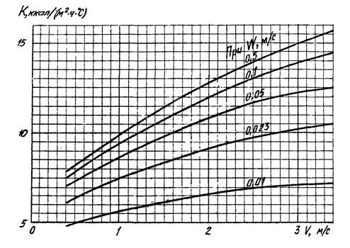
Rice. 3. Heat transfer coefficient of cast iron finned tube TO depending on air speed V (m/s) and water speed W (m/s) at twater = 100 °С
18. Determine the heating surface according to the formula (), taking the heat transfer coefficient according to p. And the air temperature at the outlet of the RW is 35 ° C, and at the inlet it is equal to the calculated air temperature in the heated room.
19. According to a certain heating surface, the number and length of finned tubes and the number of their rows in the RV are taken.
20. The amount of air circulating in the RV is determined by the formula
|
(3) |
where h — distance from the center of heating to the center of the air outlet from the RV, m; β is the average increment in the volumetric weight of air when it is heated by 1 °C, kg/m2∙°C; n - the number of rows of pipes along the air flow; fv — area of open section of RV in air, m2; ξ is the coefficient of local resistance at the entrance and exit from the RV; m — the ratio of the area of the free cross section for water to the area of the free cross section for air; A - coefficient of local resistance of the pipe or according to the simplified formulas given in table. .
|
Finned tube length, m |
Number of rows in the direction of air |
Air consumption Z, kg/h |
|
1 |
2 |
|
|
1 |
3 |
|
|
1 |
4 |
|
|
1,5 |
2 |
|
|
1,5 |
3 |
|
|
1,5 |
4 |
|
|
2,0 |
2 |
|
|
2,0 |
3 |
|
|
2,0 |
4 |
Notes 1. h — distance from the center of heating to the center of the outlet of the air duct, m.
2. Qrv — heat load of the air heater, kcal/h.
3. When installing four rows of pipes along the air flow, it is necessary that the height from the surface of the upper pipe to the center of the outlet is at least 1.5 m.
21.The air temperature difference in the RV is determined by the formula
|
(4) |
22. Air speed PB is determined by the formula
|
(5) |
where γ = 1.184 kgf/m3.
23. At a certain air speed according to the graph in fig. determine the heat transfer coefficient.
24. The heat output of the RV is determined with its actual heating surface and the refined heat transfer coefficient according to the formula
|
Qrv = KFΔtWed. |
(6) |
VIII. INSTRUCTIONS FOR USE
57. Before the start of the heating season, the porches of the entrance doors and windows of the LC are sealed, and the entrance doors are equipped with self-closing devices (closers).
58. When starting the RV valve 1, 2, 4, 5 and taps 6, 9 must be open and the valve 3 and taps 7, 8 closed (see fig. ), after venting and flushing, drain cock 9 close and the faucet 7 open.
59. Gate valve 3 on the jumper with a full passage of water through the RV should always be closed, and with a partial passage of water and the presence of a diaphragm during system operation, it should be completely open.
60. Emptying the RV and connections to it when the heating system is running is carried out through drain valves 8, 9 with closed taps 6 and 7 and open valve 3.
61. Before the start of the heating season, hydropneumatic flushing is carried out together with the heating unit.
62. Systematically monitor the state of contamination of the fins of the heating elements and, if necessary, clean them with a vacuum cleaner followed by blowing.
63
When accepting heating systems for operation, special attention is paid to the correct installation of the heating elements and the construction of the RV fences (casing), which must fit snugly against the fins.
64. Insufficiently functioning RVs, in which heating elements are installed incorrectly, their guards are missing, there are large gaps between the fins and the casing, as well as those connected in parallel to the heating system, are subject to reconstruction in accordance with these recommendations.
LITERATURE
1. Grudzinsky M.M., Ivanov V.M. Air heating of stairwells of multi-storey buildings. "Mosproekt", No. 3, M., 1958.
2. Shapovalov I.S. Heating of staircases with heating elements embedded in landings. Inf. message No. 18 "Special architectural and planning department of Moscow" M., 1958.
3. Ivanov V.M., Grudzinsky M.M. The use of air heating combined with supply and exhaust ventilation in modern housing and civil construction. "Water supply and sanitary engineering", 1958, 18.
4. Recommendations for the design and calculation of recirculating air heaters for heating stairwells in multi-storey buildings. M., 1950.
5. Ivanov V.M. Investigation of the temperature and humidity regime in the stairwells of multi-storey buildings heated by recirculation air heaters with natural impulse. Sat. Proceedings of the Research Institute of Sanitary Engineering, "Heating and ventilation", Gosstroyizdat, 1961.
6. Mikhailov L.M. Design of heating cabinets. On Sat. Proceedings of "Mosproekt", No. 3, M., 1963.
7. Ivanov V.M. The use of high convectors for heating public buildings and stairwells, materials for a scientific and technical conference on convector heating. M., 1965.
8. Ivanov V.M. Guidelines for the use and calculation of recirculating air heaters (manual for designers) NI-572 (2nd edition). MNIITEP. M., 1967.
9. Kamenev P.N. etc. Heating and ventilation. M., Stroyizdat, 1975.
10. Recirculating air heaters with Comfort heating elements 20 RV1M, RV2M, RV5M, RV6M, RI 3105. MNIITEP. 1976.
11. Construction catalog, part 10. Sanitary equipment, appliances and automatic devices, sec. 1. GPI Santekhproekt of Glavpromstroyproekt of Gosstroy of the USSR, M.
Payment for heating in the absence of radiators
S. N. Kozyreva
Journal "Housing and Communal Services: Accounting and Taxation" No. 12/2015
Is the utility service provider entitled to demand payment for heating from the owner of the premises if there are no radiators in it?
In practice, utility service providers often face the question of whether they have the right to charge a heating fee and require it to be paid by the owners of premises in which there are no heating devices. Let's consider how it is solved in two situations: if there are no heating radiators in the project room and if they have been dismantled.
The basis for charging the consumer for heating is the provision of the relevant service. By virtue of paragraph 2 of Art. 539 of the Civil Code of the Russian Federation, an energy supply agreement is concluded with a subscriber if he has a power receiving device that meets the established technical requirements, connected to the networks of an energy supply organization, and other necessary equipment, as well as providing accounting for energy consumption. According to paragraphs. "e" of clause 4 of the Rules for the provision of public services, the consumer can be provided with such a public service as heating, that is, the supply of thermal energy through centralized heat supply networks and in-house engineering heating systems, which ensures maintenance in a residential building, residential and non-residential premises in MKD, premises included in the common property of the house, the proper air temperature.