The choice of heating element
When choosing a heating element, it is necessary to pay attention to some details. Only in this case, you can count on a successful purchase, high-quality heating, service life and compatibility of the selected model with a tank for heating water, a boiler or a heating battery
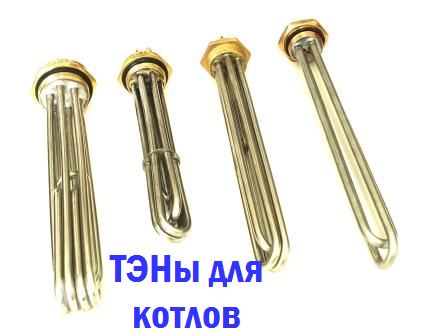
Shape and size
Dozens of models of heating elements are presented at the choice of buyers. They have a different shape - straight, round, in the form of "eight" or "ears", double, triple and many others. When buying, you should focus on the use of a heater. Narrow and straight models are used for embedding in sections of radiators, since there is not enough space inside
When assembling a storage water heater, you should pay attention to the volume and shape of the tank, and on the basis of this, choose a suitable heating element. In principle, almost any model will fit here.
If you need to replace the heating element in an existing water heater, you must purchase an identical model - only in this case you can count on the fact that it will fit in the tank itself.
Power
If not everything, then a lot depends on power. For example, it could be the heating rate. If you are assembling a small volume water heater, then the recommended power will be 1.5 kW. The same heating element can also heat disproportionately large volumes, only it will do this for a very long time - with a power of 2 kW, it can take 3.5 - 4 hours to heat 100-150 liters of water (not to boil, but on average by 40 degrees).
If you equip a water heater or water tank with a powerful heating element of 5-7 kW, then the water will heat up very quickly. But another problem will arise - the house electrical network will not withstand. When the power of the connected equipment is higher than 2 kW, it is necessary to lay a separate line from the electrical panel.
Protection against corrosion and scale
When choosing heating elements for heating water with a thermostat, we recommend paying attention to modern models equipped with anti-scale protection. Recently, models with enamel coating have begun to appear on the market.
It is she who protects the heaters from salt deposits. The guarantee for such heating elements is 15 years. If there are no similar models in the store, then we recommend buying stainless steel electric heaters - they are more durable and reliable.
The presence of a thermostat
If you assemble or repair a boiler or want to equip a heating battery with a heating element, choose a model with a built-in thermostat. It will allow you to save on electricity, turning on only when the water temperature drops below a predetermined mark. If there is no regulator, you will have to monitor the temperature yourself, turning the heating on or off - this is inconvenient, uneconomical and unsafe.
Purpose of heating elements
Why do we need heating elements with thermostats? On their basis, autonomous heating systems are designed, boilers and instantaneous water heaters are created.
For example, heating elements are mounted directly into batteries, as a result of which sections are born that can work independently, without a heating boiler. Separate models are focused on the creation of anti-freeze systems - they maintain a low positive temperature, preventing freezing and subsequent rupture of pipes and batteries.
A heating element with a thermostat is built into this battery, with its help the house is heated.
On the basis of heating elements, storage and instantaneous water heaters are created. The purchase of a boiler is far from available for every person, so many assemble them on their own using separate components. By inserting a heating element with a thermostat into a suitable container, we will get an excellent storage-type water heater - the consumer will only need to equip it with good thermal insulation and connect it to the water supply.
Also, on the basis of heating elements, storage water heaters of bulk type are created. In fact, this is a container of water filled by hand.Heating elements are also built into the tanks of the summer shower, providing heating of water to a predetermined temperature in bad weather.
Heating elements for heating water with a thermostat are necessary not only for the creation of water heating equipment, but also for its repair - if the heater is out of order, we buy a new one and change it. But before that, you need to understand the issues of choice.
Power measurement. Power measurement in DC and single-phase current circuits
Power
in DC circuits, consumed
this site
electrical circuit is equal to:
and maybe
measured with ammeter and voltmeter.
Apart from
inconvenience of simultaneous counting
readings of two instruments, measurement
power in this way is produced with
inevitable error. More convenient
measure power in DC circuits
current with a wattmeter.
measure
active power in the AC circuit
current with an ammeter and voltmeter is impossible,
because The power of such a circuit depends on
cosφ:
So in chains
AC active power
measured only with a wattmeter.
Figure 8
motionless
winding 1-1 (current) turns on
sequentially, and mobile 2-2
(voltage winding) in parallel with
load.
For
correct inclusion of the wattmeter one
from the terminals of the current winding and one of
clamps
voltage windings are marked with an asterisk
(*). These clamps, called generator clamps,
necessary
turn on from the power supply,
merging them together. In this case
the wattmeter will show the power,
coming from the side of the network (generator) to
receiver of electrical energy.
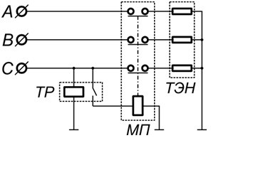
Consider connecting a three-phase heating element through a magnetic starter and a thermal relay.
Rice. one
The heating element is connected through one three-phase MP with normally closed contacts (Fig. 1). Controls the starter of the thermal relay TP, the control contacts of which are open when the temperature on the sensor is below the set one. When a three-phase voltage is applied, the starter contacts are closed and the heating element is heated, the heaters of which are connected according to the "star" scheme.
Rice. 2
When the set temperature is reached, the thermal relay turns off the power to the heaters. Thus, the simplest temperature controller is implemented. For such a regulator, you can use the RT2K thermal relay (Fig. 2), and for the starter, a contactor of the third magnitude with three opening groups.
RT2K is a two-position (on/off) thermal relay with a copper wire sensor with a temperature setting range from -40 to +50°C. Of course, the use of one thermal relay does not allow maintaining the required temperature accurately enough. Turning on each time all three sections of the heating element leads to unnecessary energy losses.
Rice. 3
If you implement the control of each section of the heater through a separate starter associated with its own thermal relay (Fig. 3), then you can more accurately maintain the temperature. So, we have three starters, which are controlled by three thermal relays TP1, TP2, TP3. The response temperatures are selected, let's say t1
Rice. 4
Temperature relays provide switching of the executive circuit up to 6A, at a voltage of 250V. To control a magnetic starter, such values are more than enough (For example, the operating current of PME contactors is from 0.1 to 0.9 A at a voltage of 127 V). When AC current is passed through the armature coil, a low power frequency hum of 50 Hz is possible.
There are thermal relays that control the current output with a current value from 0 to 20 mA. Also, often thermal relays are powered by low voltage DC (24 V). To match this output current with low voltage (24 to 36 V) starter armature coils, a level matching circuit on the transistor can be used (Fig. 5)
Rice. 5
This scheme works in key mode. When current is applied through the contacts of the TR thermal relay through the resistor R1, the current amplifies to the VT1 base and the MP starter is turned on.
Resistor R1 limits the current output of the thermal relay to prevent overload.Transistor VT1 is selected based on the maximum collector current, which exceeds the contactor actuation current and the collector voltage.
Let's calculate the resistor R1 using an example.
Assume that a direct current of 200mA is sufficient to control the starter armature. The current gain of the transistor is 20, which means that the control current of the base IB must be maintained within the limits of up to 200/20 = 10 mA. The thermal relay delivers a maximum of 24V at a current of 20mA, which is quite enough for the armature coil. To open the transistor in the key mode, a base voltage of 0.6 V must be maintained relative to the emitter. Let us assume that the resistance of the emitter-base transition of an open transistor is negligibly small.
This means that the voltage at R1 will be 24 - 0.6V = 23.4 V. Based on the previously obtained base current, we obtain the resistance: R1 = UR1 / IB = 23.4 / 0.01 = 2.340 Kom. The role of the resistor R2 is to prevent the transistor from turning on from interference in the absence of a control current. Usually it is chosen 5-10 times more than R1, i.e. for our example will be approximately 24 KΩ.
For industrial use, relay-regulators are produced that realize the temperature of the object.
Write comments, additions to the article, maybe I missed something. Take a look at , I will be glad if you find something else useful on mine.
Connecting a heating element with a thermostat
Consider the principle of operation and the switching circuit.
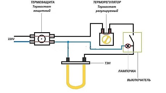
They are used for boilers and heating boilers. We take a universal one for 220V and 2-4.5 kW, ordinary, with a sensitive element in the form of a tube, it is placed inside the heating element, in which there is a special hole.
Here we see 3 pairs of heating elements, a total of six, you need to connect as follows: we put zero on three and on the other 3 - phase. We insert our device into the chain break. It has three contacts, the photo below shows one in the center on top and two on the bottom. The upper one is used to turn on to zero, and which of the lower ones to the phase must be checked by a tester.
Therefore, the power of the 1st heating element may not match the parameters for heating the vessel and be more or less. In such cases, to obtain the required heating power, you can use several heating elements connected in series or in series-parallel. By switching various combinations of heating elements connection, a switch from a household electric. plates, you can get different power. For example, having eight embedded heating elements, 1.25 kW each, depending on the switching combination, you can get the following power.
- 625 W
- 933 W
- 1.25 kW
- 1.6 kW
- 1.8 kW
- 2.5 kW
This range is quite enough to regulate and maintain the desired temperature. But you can get other power by adding the number of switching modes and using various switching combinations.
Serial connection of 2 heating elements of 1.25 kW each and connecting them to a 220V network gives a total of 625 watts. Parallel connection, in total gives 2.5 kW.
We know the voltage acting in the network, it is 220V. Further, we also know the power of the heating element knocked out on its surface, let's say it is 1.25 kW, which means we need to find out the current flowing in this circuit. The current strength, knowing the voltage and power, we learn from the following formula.
Current = power divided by mains voltage.
It is written like this: I = P / U.
Where I is the current in amperes.
P is the power in watts.
U is the voltage in volts.
When calculating, you need to convert the power indicated on the heater case in kW to watts.
1.25 kW = 1250W. We substitute the known values into this formula and get the current strength.
I \u003d 1250W / 220 \u003d 5.681 A
R = U / I, where
R - resistance in ohms
U - voltage in volts
I - current strength in amperes
We substitute the known values \u200b\u200binto the formula and find out the resistance of 1 heating element.
R \u003d 220 / 5.681 \u003d 38.725 ohms.
Rtot = R1 + R2 + R3, etc.
Thus, two heaters connected in series have a resistance of 77.45 ohms. Now it is easy to calculate the power released by these two heating elements.
P = U2 / R where,
P - power in watts
R is the total resistance of all last. conn. heating elements
P = 624.919 W, rounded up to 625 W.
Table 1.1 shows the values for a series connection of heating elements.
Table 1.1
|
Number of heating elements |
Power, W) |
Resistance (ohm) |
Voltage (V) |
Current (A) |
|
serial connection |
||||
|
2 heating elements = 77.45 |
||||
|
3 heating elements =1 16.175 |
||||
|
5 heating elements=193.625 |
||||
|
7 heating elements=271.075 |
||||
Table 1.2 shows the values for parallel connection of heating elements.
Table 1.2
|
Number of heating elements |
Power, W) |
Resistance (ohm) |
Voltage (V) |
Current (A) |
|
Parallel connection |
||||
|
2 heating elements=19.3625 |
||||
|
3 heating elements=12.9083 |
||||
|
4 heating elements=9.68125 |
||||
|
6 heating elements=6.45415 |
||||
From the point of view of electrical engineering, this is an active resistance that generates heat when an electric current passes through it.
In appearance, a single heating element looks like a bent or curled tube. Spirals can be of very different shapes, but the connection principle is the same, a single heating element has two contacts for connection.
When connecting a single heating element to the supply voltage, we just need to connect its terminals to the power supply. If the heating element is designed for 220 volts, then we connect it to the phase and working zero. If the heating element is 380 volts, then it connects the heating element to two phases.
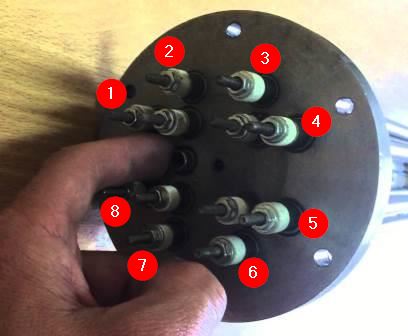
But this is a single heating element, which we can see in an electric kettle, but we will not see in an electric boiler. Heating boiler heating elements are three single heating elements fixed on a single platform (flange) with contacts brought out on it.
The most common heating element of the boiler consists of three single heating elements fixed on a common flange. On the flange, it is displayed for connecting 6 (six) contacts of the heating element of the electric heating element of the boiler. There are boilers with a large number of single heating elements, for example, like this:
Measurement of active power in three-phase current circuits
At
three-phase current power measurement
apply various
wattmeter switching circuits depending on
from:
wiring systems
(three- or four-wire);
load (uniform
or uneven)
connection diagrams
load (star or delta).
a)
power measurement with symmetrical
loads; wiring system
three- or four-wire:
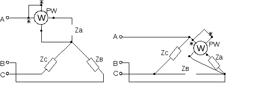
Drawing
9
Figure10
In that
case, the power of the entire circuit can be measured
one wattmeter (Figures 9.10), which
will show the power of one phase P \u003d 3P f \u003d 3U f I f cosφ
b) with asymmetric
load power of a three-phase consumer
can be measured with three wattmeters:
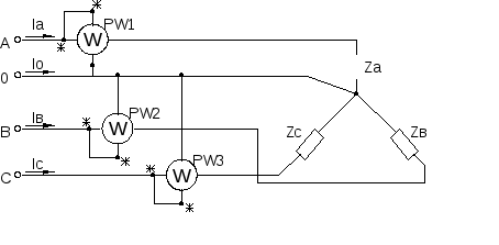
Figure 11
general power
consumer is equal to:
c) measurement
power by the method of two wattmeters:
Figure 12
Used in 3
wire systems of three-phase current
with symmetrical and asymmetrical
loads and any type of connection
consumers. In this case, the current windings
wattmeters are included in phases A and B
(for example), and parallel to linear
voltage U AC
and U sun
(or A and C
UAB
and U SA),
(Fig. 12).
general power
P=P 1 +P 2
.
Electric water heating and heating equipment has received great demand among consumers. It allows you to quickly organize heating and hot water supply with minimal initial costs. Some people even create such equipment on their own, with their own hands. A The heart of any home-made device is a heating element with a thermostat.
How to choose the right heating element and what to focus on when choosing it? There are quite a few options:
- Power consumption;
- Dimensions and shape;
- The presence of a built-in thermostat;
- Presence of protection against corrosion.
After reading this review, you will learn how to independently understand heating elements with thermostats and be able to connect them.
Consider connecting a three-phase heating element through a magnetic starter and a thermal relay.

Rice. one
The heating element is connected through one three-phase MP with normally closed contacts (Fig. 1). Controls the starter of the thermal relay TP, the control contacts of which are open when the temperature on the sensor is below the set one. When a three-phase voltage is applied, the starter contacts are closed and the heating element is heated, the heaters of which are connected according to the "star" scheme.
Rice. 2
When the set temperature is reached, the thermal relay turns off the power to the heaters. Thus, the simplest temperature controller is implemented. For such a regulator, you can use the RT2K thermal relay (Fig. 2), and for the starter, a contactor of the third magnitude with three opening groups.
RT2K is a two-position (on/off) thermal relay with a copper wire sensor with a temperature setting range from -40 to +50°C. Of course, the use of one thermal relay does not allow maintaining the required temperature accurately enough. Turning on each time all three sections of the heating element leads to unnecessary energy losses.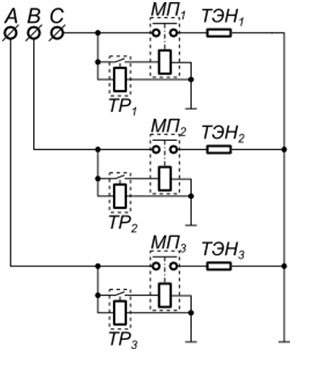
Rice. 3
If you implement the control of each section of the heater through a separate starter associated with its own thermal relay (Fig. 3), then you can more accurately maintain the temperature. So, we have three starters, which are controlled by three thermal relays TP1, TP2, TP3. The response temperatures are selected, let's say t1
Rice. 4
Temperature relays provide switching of the executive circuit up to 6A, at a voltage of 250V. To control a magnetic starter, such values are more than enough (For example, the operating current of PME contactors is from 0.1 to 0.9 A at a voltage of 127 V). When AC current is passed through the armature coil, a low power frequency hum of 50 Hz is possible.
There are thermal relays that control the current output with a current value from 0 to 20 mA. Also, often thermal relays are powered by low voltage DC (24 V). To match this output current with low voltage (24 to 36 V) starter armature coils, a level matching circuit on the transistor can be used (Fig. 5)
Rice. 5
This scheme works in key mode. When current is applied through the contacts of the TR thermal relay through the resistor R1, the current amplifies to the VT1 base and the MP starter is turned on.
Resistor R1 limits the current output of the thermal relay to prevent overload. Transistor VT1 is selected based on the maximum collector current, which exceeds the contactor actuation current and the collector voltage.
Let's calculate the resistor R1 using an example.
Assume that a direct current of 200mA is sufficient to control the starter armature. The current gain of the transistor is 20, which means that the control current of the base IB must be maintained within the limits of up to 200/20 = 10 mA. The thermal relay delivers a maximum of 24V at a current of 20mA, which is quite enough for the armature coil. To open the transistor in the key mode, a base voltage of 0.6 V must be maintained relative to the emitter. Let us assume that the resistance of the emitter-base transition of an open transistor is negligibly small.
This means that the voltage at R1 will be 24 - 0.6V = 23.4 V. Based on the previously obtained base current, we obtain the resistance: R1 = UR1 / IB = 23.4 / 0.01 = 2.340 Kom. The role of the resistor R2 is to prevent the transistor from turning on from interference in the absence of a control current. Usually it is chosen 5-10 times more than R1, i.e. for our example will be approximately 24 KΩ.
For industrial use, relay-regulators are produced that realize the temperature of the object.
Write comments, additions to the article, maybe I missed something. Take a look at , I will be glad if you find something else useful on mine.
We continue to get to know tubular electric heaters
(heating element
). In the first part, we considered, and in this part we will consider the inclusion of heaters in three-phase network
.