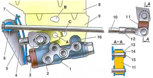
Brake pressure regulator
In order to adjust it, you need to know the basic principles of operation of this mechanism, popularly called a sorcerer.
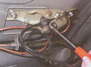
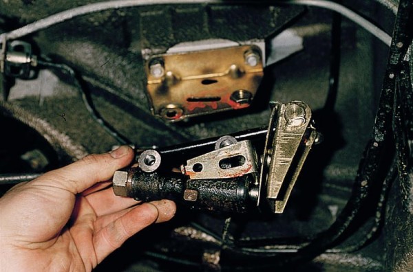
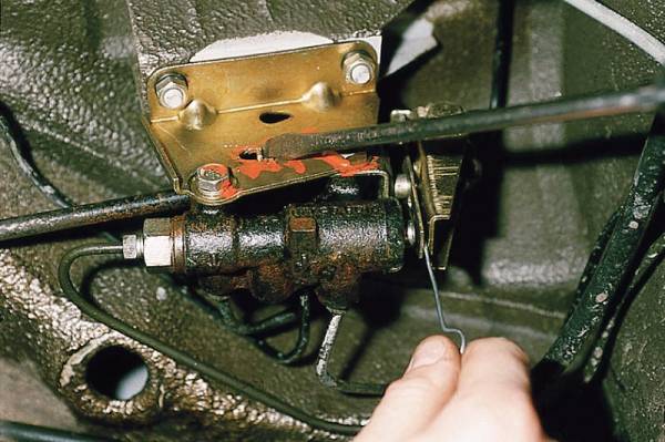
As a rule, the sorcerer is attached with two bolts from the bottom of the car. As for one of the bolts, it simultaneously fixes the fork element of the drive lever responsible for pressure.
This very element or bracket is the very object with which the movement is carried out and thus the pressure can be adjusted.
Checking the pressure regulator
To check the pressure regulator, you must:
Install the car on a jack or pit;
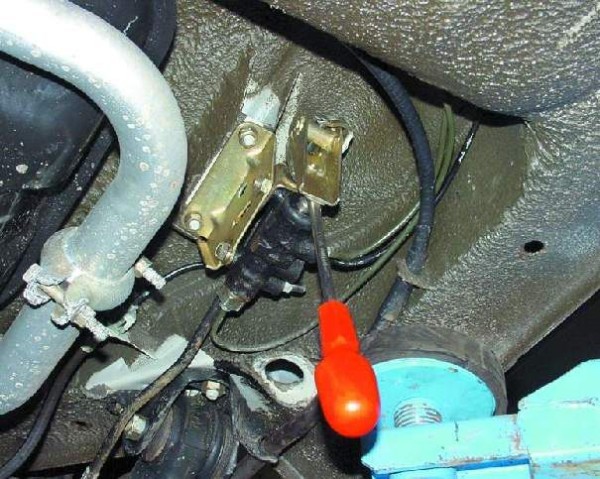
Find the regulator and clean it of dirt and oil;
Carefully inspect and decide if there is damage on the part (if any are found, the sorcerer will have to be replaced);
The assistant presses the brake pedal;
We pay attention to the piston, which should move out of the housing by a few millimeters (2 mm), while compressing the leaf spring to the stop.
Sorcerer Adjustment
To adjust the sorcerer, you must:
- Press the rear of the car, applying a force of fifty kgf to the rear bumper (thus, the rear suspension will be in the middle position);
- Install the rods between the body and the rear suspension arms;
- Now you should visually inspect the gap, which is located between the lower part of the sorcerer's drive lever and the spring (it should be equal to 2 mm);
- Adjustment is carried out using a special tool.
Handbrake
It is also necessary to adjust the manual parking brake system. If its functionality is incorrect, jamming of the brake pads may occur.
It must be adjusted after 30,000 km of vehicle operation or at the first sign of poor quality work. To adjust, you will need:
- garage room with a viewing hole,
- the usual set of keys.
Let's get started:
- Engage forward gear.
- Put stops under the front wheels for reliability.
- The rear suspension of the car must be raised with a jack, substitute reliable props.
You need to start by checking the lever, which is located in the passenger compartment between the two front passenger seats. Raise it two or three clicks.
When lifting, one click is made, which means it will be pulled. This leads to blocking of the rear drums with brake pads. If more than 8 are produced, then the cable is loose, the handbrake does not work:
- With the handbrake on, go down into the inspection hole.
- Loosen the first lock nut on the equalizer.
- Tighten the second nut so that the cable is in a taut position.
- Release if necessary.
- Check lever operation. It should work in two or three clicks.
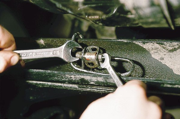
Then tighten the first nut from the pit, tighten with two wrenches to get the effect of tightening two nuts:
- Then turn off the parking system.
- Check rear wheel rotation.
Make rotational movements with your hands. Their rotation should take place without a jerk, calmly scrolling along the axis of the car.
The sound should come out rustling. Therefore, the adjustment of the brake system of the car was carried out successfully.
The vehicle is ready for continued operation. The brakes can also be adjusted in a car workshop.
You can entrust this work to specialists. But the motorist experiences reliability when this work is done independently.
A car can be considered technically sound when it is independently inspected and repaired. He will never let you down in a difficult, dangerous moment.
In addition, the price of repairs in the service station is high. When doing work with your own hands, you must carefully watch the video.
You also need to study the photo, if necessary, take them to the place of repair. Lay out on a rack or in the back seat of a car.
Review them again if necessary. Read the instructions for the operation, the locations of the necessary structures.
Finish the adjustment, check the work done on a free asphalt area.
The VAZ brake pressure regulator, like any other vehicle, is a device whose functional purpose is to ensure stability, that is, the ability of the car to maintain a given direction and position on the roadway during braking.
The practical implementation of this function occurs as a result of the conversion of the braking force value due to the influence of the following factors:
pressing the brake pedal by the driver;
degree of loading of the vehicle;
braking intensity.
What dictated the need for a pressure regulator? First of all, safety. Even the highest quality tires do not guarantee the absence of slippage of the tread elements relative to the roadway in the longitudinal direction, which, in turn, initiates a decrease in wheel resistance to forces directed perpendicular to the vehicle axis. There is a so-called "use".
Any brake mechanism, regardless of its design, blocks the wheel to one degree or another.
However, it is quite important in what particular sequence the blocking and the “use” provoked by it occur. The least dangerous option is considered in which the blocking of the front wheelset occurs earlier than the blocking of the rear.
The use of a brake pressure regulator in the brake system is designed to provide just such a sequence of wheel locks.
Types of pressure regulators
Based on the law of regulation that underlies the work, pressure regulators are isodromic, static
and astatic
.
V astatic regulators
(Figure 1, a) the membrane (sensing element) is affected by a constant force from load 2. The opposing (active) force is the gain perceived by the membrane from the outlet pressure P2. If the gas extraction from the network 4 increases, the pressure P2 will decrease, which will lead to a violation of the balance of forces, as a result of which the membrane will go down and the regulatory body will open.
Regulators of this type, after the disturbance, bring the regulated pressure to the value that is set, regardless of the magnitude of the load, as well as the position occupied by the regulatory body. The equilibrium of the system can only occur at a given pressure value, which is regulated, and the regulatory body can occupy any position. Regulators of this type should be operated on networks with high self-balancing, for example, in low-pressure gas networks with a sufficiently large capacity.
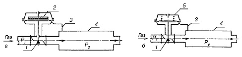
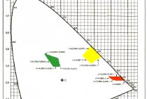
Figure 1. Diagrams of pressure regulators:
a - astatic regulator; b - static pressure regulator; 1 - regulatory (throttle) body; 2 - membrane-cargo drive; 3 - impulse tube; 4 - the object of regulation - the gas network; 5 - membrane-spring drive.
Articulation friction and backlash can cause regulation to become unstable. In order to stabilize this process, hard feedback is introduced into the pressure regulator. Regulators of this type are called static
. During the static control process, the equilibrium value of the pressure that is being controlled always differs from the set value, and only at nominal load do the actual and nominal values become equal. Static gas pressure regulators are characterized by unevenness.
In the regulator in Figure 1, b, instead of a load, a spring is used - a stabilizing device. The force developed by the spring is directly proportional to its deformation. When the diaphragm is in the upper limit position, i.e., the regulator is closed, the spring has the highest compression ratio, and P2 is the maximum. When the regulator is fully open, the value of P2 becomes minimum. The static characteristic of the regulators is chosen to be flat, so that the unevenness of the gas pressure regulator is small, and the regulation process becomes damped.
Regulator with elastic feedback, or isodromic regulator
in the event of a regulated pressure deviation, P2 will first move the control element by an amount proportional to the deviation. However, if the pressure P2 does not normalize to the set value, then the movement of the regulating element will be carried out until the pressure P2 reaches the required set value.
Pedal adjustment
- Raise the hood.
- Disconnect the negative terminal from the battery.
- Slide the front driver's seat from the instrument panel all the way to the rear passenger seats. This must be done for easy access under the steering column.
- Hang the prepared lantern inside the car to provide sufficient lighting at the place where the adjustment is to be made.
- Press the palm of your hand on the brake pedal. Pressing to carry out without sharp shocks.
- With the other free hand, try to install the plate in the gap from the pedal bracket to the switch button.
If the plate does not enter or if a larger gap is found, more than 2 mm, the following actions must be carried out:
- Hold the pedal with your hand without releasing.
- With the second hand, using a wrench, slightly unscrew the two nuts along the thread. To loosen the brake warning light switch.
Move it carefully to achieve the required space between it and the brake pedal:
- Tighten one nut first, then tighten the second.
- Take your hand off the pedal.
- Check completed operations.
- The switch buffer rests against the brake pedal bracket, the adjustment is considered complete.
Device features
The structure of the regulator.
According to the features of the structure and principles of operation, gearboxes can be divided into 2 types:
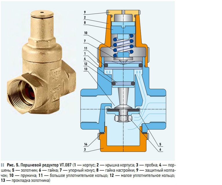
- “To yourself” - devices that stabilize the pressure of the liquid in the pipeline section to the device. They are mainly used in pumping stations. Devices of this type operate in automatic mode. The main working elements are a balancing saddle and a movable piston that regulates the gap. The size of this gap depends on the water pressure, and the pressure reducing valve remains open until the required water pressure in the pipeline is established.
- “After yourself” - reducers that regulate the pressure in the pipe section after the device. The main working part is a piston with a rod, at the end of which a plate is installed. If water enters the device under high pressure, then the liquid begins to act on the membrane, which is supported on the reverse side by a spring. This action is transmitted along the stem to the plate, which moves towards the seat. Thus, the gap between the valve disc and the seat decreases, and this leads to a decrease in the water pressure in the line.
Varieties of pressure regulators

The performance parameters of household type devices do not exceed three cubic meters per hour.
Modern water pressure reducers are very in demand and diverse, which makes it possible to classify these devices, taking into account several features:
The main of the selection criteria, which allows you to subdivide water pressure control devices into domestic, commercial and industrial types.The performance parameters of household type devices do not exceed three cubic meters per hour.
For commercial gearboxes, this figure is from three to fifteen cubic meters, and the industrial type of regulators has a capacity of over fifteen cubic meters in the same period of time.
For connection in conditions of two inch pipelines, a threaded type of reducer is to be used. The flange variety is used for arranging pipes with larger diameters.
maximum inlet pressure
Devices are available for installation in plumbing systems with pressure parameters not exceeding sixteen bar or more powerful devices that can withstand almost twenty-five bar.
maximum operating temperature
Devices for cold water supply with a maximum value of 40 °C and regulators for installation on a hot water system that can withstand a temperature regime of 70 °C.
Regulator device
The pressure regulator device contains two components - a regulating element and an actuating part. The main part of the executive part is called a sensitive element that compares the signal coming from the setpoint with the current pressure indicators. After that, the executive part converts the received signal into a regulatory action. It is worth noting that there are direct and indirect action regulators, but both of these types have both intermittent and continuous action. Direct acting regulators have a direct control element that acts by force. Devices with indirect action actuate the control element with the help of a third-party source, for example, air, gas, or liquid.
DIRECT ACTING PRESSURE REGULATORS

With direct-acting pressure regulators, the control device is driven by a diaphragm that is under the influence of an adjustable pressure.
A change in the regulated (working) pressure causes a displacement of the membrane, and through the transmission mechanism, a change in the amount of gas passage through the control device of the pressure regulators.
Thus, the pressure regulator responds to a change in the operating pressure by changing the amount of gas passed through.
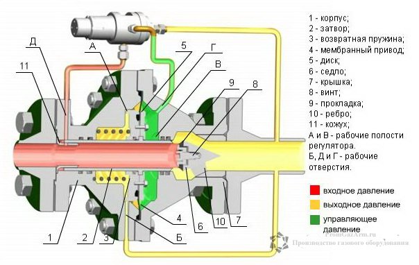
The principle of operation of the direct acting pressure regulator is shown in the figure.
The pressurized gas enters the inlet of the regulator, then passes through the valve seat 2 and leaves the regulator through the outlet 3. The regulator must maintain a constant working pressure behind it under conditions of variable flow.
With a change in gas flow, the working pressure will change, which acts from below on the membrane 4. With an increase in gas flow, the pressure at the first moment will drop somewhat and the force acting on the membrane from below will decrease slightly, as a result of which, under the action of load 5, the membrane, together with valve 6, will shift to some amount down and increase the gas passage. The pressure will rise to its previous value.
With a decrease in gas flow, the pressure at the first moment will increase slightly and the membrane will move upward, covering the flow area for gas with a valve. Reducing the gas supply through the regulator will cause a decrease to the original value.
Thus, the pressure regulator will maintain the operating pressure at a given level, which is determined by the membrane load.
Considering that the variety of designs of pressure regulators is very large, only those designs that are widely used in urban gas supply will be considered.
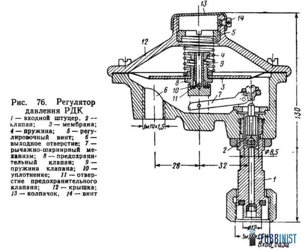
Pressure regulator RDK.The normal operation of household gas appliances to a large extent depends on the constancy of gas pressure in the domestic gas networks.
When supplying household consumers with liquefied gas, a pressure regulator of the RDK type is used, which is used in cylinder installations and is designed for an initial pressure of up to 16 kgf / cm2.
The outlet pressure can be adjusted within 100-300 mm of water. Art. The performance of the regulator with a pressure drop of 1 kgf/cm2 and a propane-butane mixture specific gravity of about 2 kg/m3 is 1 m3/h. On fig. the regulator device is shown.
High-pressure gas enters through the inlet fitting under valve 2 with a seal made of oil, gasoline and frost-resistant rubber. The position of the valve in relation to the seat located on the inlet fitting is determined by the position of the membrane 3 connected to the valve by a lever-hinge mechanism.
Spring 4 acts on the membrane from above, and gas pressure from below. The compression of the spring is regulated by screw 5, which is used to adjust the regulator to the operating pressure. In this case, the gas, passing through the valve, will flow through the outlet 6 of the regulator to the gas appliances. gas flow through the regulator. A safety valve 8 is mounted in the regulator membrane, which operates as follows: when the valve 2 is closed and the pressure under the membrane rises above the set value (in the absence of gas flow and the valve is not tightly closed), the membrane, overcoming the action of spring 4 and spring 9 of the safety valve 5, will move away from seals 10 and relieves excess gas pressure through the hole under the top cover 12 of the regulator, which is connected by an exhaust pipe to the atmosphere.
After adjusting the regulator to a certain working pressure, the adjusting screw 5 is closed with a cap 13 and fixed with a screw 14, which is sealed. Subscribers are prohibited from adjusting the gas pressure with screw 5.
To create normal operating conditions for the pressure regulator, when the valve position is in the control area, its calculated performance should be approximately 20% more than the required maximum performance of the regulator. For this reason, it is recommended to select the regulator so that it is loaded at the required capacity by no more than 80%, and at the minimum flow rate by at least 10%.
Pressure regulator RDK
Examination
Necessary:
- Raise the rear axle of the car with a jack.
- Remove wheel rims.
- Take off .
- Inspect the brake cylinders for leaks.
- Also check their operation, the cylinders should reach the distance required for braking.
- After releasing the pedal, they should not jam. If this defect is found, the cylinders must be replaced.
- Check the condition of the springs, they should not have spiral bends. They must also have a flat surface.
- Inspect the quality of the pads themselves. They should not have delaminations, the thickness should be at least 2/3 of the standard.
- Also inspect the spacer bar, it should not have any defects, since a damaged bar can disrupt the operation of the pads.
- Check brake drums. They should not have burrs, large grooves from the operation of the pads.
For regulation it is necessary:
- plate 3 mm thick;
- a set of keys;
- portable lamp with a protective glass dome, with a protective steel mesh.
The process of adjusting the free play of the brake pedal is carried out to ensure the normal functionality of the entire system. If the stroke is reduced, then the rear pads do not fully return to their position. This causes them and the drums to heat up.
There is also uneven acceleration at the beginning of the movement. With increased free play, pressing the pedal, incomplete expansion occurs.
Terms that are used to characterize the operation of gas pressure regulators
-
Relative leakage
. Relative leakage is the ratio of the maximum value of water leakage through the valve of the regulatory body at a conditional throughput Kv and a pressure drop of 0.1 Megapascal. -
Conditional capacity Kv.
This is the name of a value that is equal to the flow rate of water with a density of 1 g / cm³ (1000 kg / m³) in cubic meters per hour through the regulator at the full (nominal) stroke of the valve, and a pressure drop of 0.1 MPa (1 kg / cm²). -
Proportional zone.
The proportional band is the change in pressure that is regulated, which is necessary in order to move the valve (regulating body) by the value of its full (nominal) stroke. -
Dead zone.
The dead zone is the difference in the regulated pressure required to change the direction of movement of the regulating body. -
Regulatory zone.
The regulation zone is the difference between the regulated pressures at ten and ninety percent of the maximum flow. -
Upper pressure setting limit.
This is the name of the maximum outlet pressure to which the regulator can be adjusted. -
Setting range.
The setting range is the difference between the lower and upper pressure limits between which the pressure regulator can be adjusted. -
Valve travel
. The stroke of a valve is the distance the valve travels from the seat. -
Dynamic error
. The dynamic error is the maximum pressure deviation during the transition period from one regime to another. -
static error
. A static error is a pressure deviation, which is regulated, from a given one in steady state. The static error is also called control unevenness.