Design bandwidth calculation methods
- length of the main system;
- the material from which the products are made;
- number of water points and so on.
To date, there are several ways to help calculate the throughput of a structure.
Special formula. We will not go into it too much, since it will not give anything to an ordinary person without special knowledge. Let us just clarify that in such a formula averaged indicators are used, such as the roughness coefficient or Ksh. For a certain type of system and a period of time, it is different. If we calculate the throughput of a pipe made of steel (not previously operated), then the Ksh indicator will correspond to 0.2 mm.

Accurate throughput calculation requires knowledge of tabular data corresponding to a particular material.
But still, this data alone is not enough.
Tables. Accurate throughput calculation requires knowledge of tabular data corresponding to a particular material.
There are a number of tables for hydraulic calculation of pipes made of steel, plastic, asbestos cement, glass, and so on. As an example, we can cite the table F.A. Shevelev.
Specialized programs for optimizing water supply networks. The method is modern and greatly facilitates the task of calculating. In such a program, the maximum value of all values for any type of product is determined. The principle of operation is the following.
After entering into the program certain mandatory values, you get all the necessary parameters. The most expedient is to use the program when laying a large water supply system, to which water points are connected en masse.
The parameters taken into account when using a special program are as follows:
There are specialized programs for calculating the throughput of a pipe, you only need to enter certain mandatory values \u200b\u200binto the program and all the necessary parameters will be calculated.
- section length;
- the size of the internal diameter of the structure;
- roughness coefficient for a specific material;
- coefficient of local resistance (this is the presence of bends, tees, compensators, etc.);
- degree of overgrowth of the main system.
Any of the above methods will provide you with an accurate result of the throughput of the elements, and of the entire water supply system in the house. Having made a qualitative calculation, it is easy to avoid the difficulties associated with poor water supply or its absence at all.
Pipe capacity table
| Type of pipeline system | Speed indicator (m/s) |
| For aquatic working environment | |
| 1. City knot | from 0.60 to 1.50 |
| 2. Highways of the main character | from 1.50 to 3.00 |
| 3. Central heating | from 2.00 to 3.00 |
| 4. Pressure systems | from 0.75 to 1.50 |
| 5. Fluids of a hydraulic nature | up to 12 |
| For oil (hydraulic fluids) | |
| 1. Pipelines | from 3.00 to 7.5 |
| 2. Pressure systems | from 0.75 to 1.25 |
| For couple | |
| 1. Heating systems | from 20.0 to 30.0 |
| 2. Systems of a central character | from 30.0 to 50.0 |
| 3. High temperature heating systems | from 50.0 to 70.0 |
| For air and gas media | |
| 1. Main systems of a central nature | from 20.0 to 75.0 |
information theory bandwidth channel 2
I've read a few articles online and I've got a pretty good understanding of TCP and UDP in general. However, I still have some doubts that I'm sure are not entirely clear to me.
( )
UPDATE:
I figured out that TCP uses windows, which are nothing more than many segments that can be sent before they actually wait for Thanks. But I doubt that UDP segments are constantly being sent without even bothering with Thanks. So there is no additional overhead in UDP. Then why is TCP throughput so much higher than UDP throughput?
And finally
It's true ?
If so, then the TCP throughput is always equal to the Know Link speed. And because RTT cancels each other out, TCP throughput doesn't even depend on RTT.
I have seen in some network analysis tools like iperf, throughput performance test, etc. that TCP/UDP throughput varies with block size.
Tabular calculation of sewer pipes
-
Non-pressure sewerage
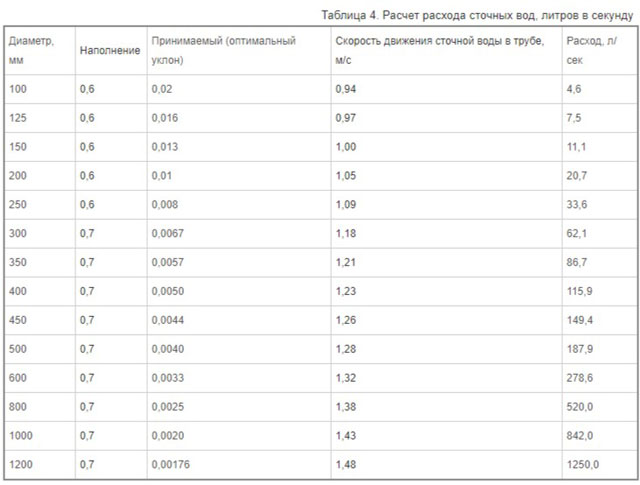
. To calculate non-pressure sewer systems, tables are used that contain all the necessary indicators. Knowing the diameter of the installed pipes, you can select all other parameters depending on it and substitute them into the formula. In addition, the table shows the volume of liquid passing through the pipe, which always coincides with the pipeline's permeability. If necessary, you can use the Lukin tables, which indicate the throughput of all pipes with a diameter in the range from 50 to 2000 mm. -
Pressure sewer
. It is somewhat easier to determine the throughput in this type of system using tables - it is enough to know the maximum degree of filling of the pipeline and the average speed of liquid transportation.
The throughput table of polypropylene pipes allows you to find out all the parameters necessary for arranging the system.
Calculation of the capacity of sewer pipes
When designing a sewer system, it is imperative to calculate the throughput of the pipeline, which directly depends on its type (sewer systems are pressure and non-pressure). Hydraulic laws are used to carry out calculations. The calculations themselves can be carried out both using formulas and using the corresponding tables.
For the hydraulic calculation of the sewer system, the following indicators are required:
- Pipe diameter - Du;
- The average speed of movement of substances - v;
- The value of the hydraulic slope - I;
- Degree of filling – h/DN.
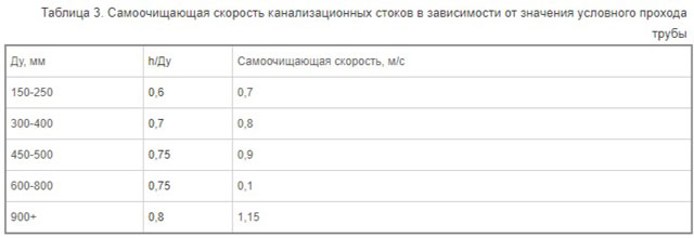
The speed and maximum level of filling domestic sewage are determined by the table, which can be written as follows:
- Diameter 150-250 mm - h / DN is 0.6, and the speed is 0.7 m / s.
- Diameter 300-400 mm - h / DN is 0.7, speed - 0.8 m / s.
- Diameter 450-500 mm - h / DN is 0.75, speed - 0.9 m / s.
- Diameter 600-800 mm - h / DN is 0.75, speed - 1 m / s.
- Diameter 900+ mm - h / DN is 0.8, speed - 1.15 m / s.
For a product with a small cross section, there are normative indicators for the minimum slope of the pipeline:
- With a diameter of 150 mm, the slope should not be less than 0.008 mm;
- With a diameter of 200 mm, the slope should not be less than 0.007 mm.
The following formula is used to calculate the volume of wastewater:
q = a*v,
Where a is the free area of the flow;
v is the speed of effluent transportation.
The rate of transport of a substance can be determined using the following formula:
v=C√R*i,
where R is the value of the hydraulic radius,
C is the wetting coefficient;
i - the degree of slope of the structure.
From the previous formula, you can derive the following, which will determine the value of the hydraulic slope:
i=v2/C2*R.
To calculate the wetting coefficient, a formula of the following form is used:
С=(1/n)*R1/6,
Where n is a coefficient that takes into account the degree of roughness, which varies from 0.012 to 0.015 (depending on the pipe material).
The R value is usually equated to the usual radius, but this is only relevant if the pipe is completely filled.
For other situations, a simple formula is used:
R=A/P
Where A is the cross-sectional area of the water flow,
P is the length of the inner part of the pipe that is in direct contact with the liquid.
Factors Affecting Internet Speed
As you know, the final speed of the Internet also depends on the bandwidth of the communication channel. Also, the speed of information transfer is affected by:
Connection methods.
Radio waves, cables and fiber optic cables. The properties, advantages and disadvantages of these connection methods have been discussed above.
Server load.
The busier the server is, the slower it receives or transmits files and signals.
External interference.
The strongest interference affects the connection created using radio waves. This is caused by cell phones, radios and other radio receivers and transmitters.
Status of network equipment.
Of course, the connection methods, the state of the servers and the presence of interference play an important role in providing high-speed Internet. However, even if the above indicators are normal, and the Internet has a low speed, then the matter is hidden in the network equipment of the computer. Modern network cards are capable of supporting an Internet connection at speeds up to 100 Mbps. Previously, cards could provide a maximum throughput of 30 and 50 Mbps, respectively.
Shipping overhead
The Internet is a best-effort network, which means that packets will be delivered if possible, but may also be dropped. Packet drops are adjusted by the transport layer, in the case of TCP; there is no such mechanism for UDP, which means that either the application does not care that some parts of the data are not delivered, or the application implements retransmission directly on top of UDP.
Retransmission reduces consumption for two reasons:
a. Some data needs to be sent again, which takes time. This introduces a latency that is inversely proportional to the speed of the slowest link in the network between the sender and receiver (aka the bottleneck). b. The detection that some data has not been delivered requires feedback from the receiver to the sender. Due to propagation delays (sometimes called latency, caused by the finite speed of light in a cable), feedback can only be received by the sender with some delay, further slowing down the transmission. In most practical cases, this is the largest contribution to the additional delay caused by retransmission.
Obviously if you use UDP instead of TCP and don't care about packet loss, you will of course get better performance. But for many applications, data loss cannot be tolerated, so this measurement is meaningless.
There are some applications that use UDP to transfer data. One is BitTorrent which can use either TCP or a protocol they created called uTP which emulates TCP over UDP but aims to make better use of many concurrent connections. Another transport protocol implemented over UDP is QUIC, which also emulates TCP and offers multiplexing of multiple parallel transmissions over a single connection and forward error correction to reduce retransmissions.
I'll be discussing forward error correction a bit since it's related to your throughput question. The naive way to implement it is to send each packet twice; in case one gets lost, the other still has a chance to get
This cuts the number of retransmissions by up to half, but also cuts your revenue in half as you send redundant data (note that network or link layer bandwidth remains the same!). In some cases, this is normal; especially if the latency is very high, for example, on intercontinental or satellite channels
Also, there are some math methods where you don't have to send a complete copy of the data; for example, for every n packets you send, you send another reduntant, which is XOR (or some other arithmetic operation) of them; if the extra is lost, it doesn't matter; if one of the n packets is lost, you can recover it based on the redundant one and the other n-1. In this way, you can tune the FEC overhead to whatever amount of bandwidth you can spare.
1. Information transfer rate in a discrete communication system
V
discrete communication system in the absence
interference information at the output of the communication channel
(PI channel) completely coincides with
information at its input, so
information transfer rate numerically
equals the performance of the source
messages:
 .(5.1)
At
the presence of interference part of the source information
the speed of information transfer is also lost
turns out to be less than the productivity
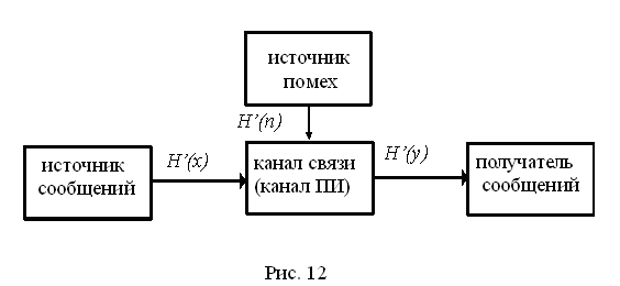
source. At the same time in the message
information is added at the output of the channel
about interference (Fig. 12).
So
in the presence of interference, it is necessary to take into account
at the output of the channel, not all information,
given by the source, but only mutual
information:
 bps (5.2)
On the
formula (5.1) we have
 or
or
 ,
,
(5.3)
where H(x)
performance
source;
H(xy)
unreliability
“ channel (loss) per unit of time;
H(y)
entropy of the output message per unit
time;
H(yx)=H’(n)
is the entropy of interference (noise) per unit time.
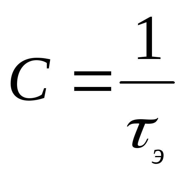
pass
communication channel capability (channel
information transfer) C
called the maximum possible
channel information rate
 .(5.4)
For achievement
maximum, all possible
output sources and all possible
coding methods.
In this way,
communication channel bandwidth
equals maximum performance
source at the channel input, completely
matched with the characteristics
this channel, minus the loss of information
channel due to interference.
In a channel without interference
C=maxH(x),
because H(xy)=0.
When using uniform code with
basis k,
consisting of n
elements with a duration uh,
in a channel without interference
 ,
,
at k=2
bit/s.
(5.5)
For effective
bandwidth usage
channel must be coordinated with
input source. Such
matching is possible both for channels
communication without interference, and for channels with
interference based on two theorems,
proved by K. Shannon.
1st theorem (for
communication channel without interference):
If the source
messages has entropy H
(bit per symbol), and the communication channel - throughput
ability C
(bits per second), then you can encode
messages in such a way that
transmit information over a channel
average speed, arbitrarily close
to the value C,
but don't overdo it.
K. Shannon suggested
and a method of such encoding, which
called statistical
optimal coding. Further
the idea of such coding was developed
in the works of Fano and Huffman and at present
time is widely used in practice
for “message compression”.
Relay costs
The Internet is a best effort network, which means that packets will be delivered if possible, but may also be dropped. Packet drops are handled by the transport layer, in the case of TCP; there is no such mechanism for UDP, which means that either the application does not care if some parts of the data are not delivered, or the application itself performs retransmission over UDP.
Retransmission reduces useful throughput for two reasons:
a. Some data needs to be sent again, which takes a long time.This introduces a delay that is inversely proportional to the speed of the slowest link in the network between the sender and receiver (which is also the bottleneck). b. The detection that some data has not been delivered requires feedback from the receiver to the sender. Due to propagation delays (sometimes called latency; caused by the finite speed of light in the cable), feedback can only be received by the sender with some delay, further slowing down the transmission. In most practical cases, this is the most significant contribution to the additional delay caused by retransmission.
It is clear that if you use UDP instead of TCP and don't care about packet loss, you will of course get better performance. But for many applications, data loss is unacceptable, so such a measurement does not make sense.
There are some applications that use UDP to transfer data. One of them is BitTorrent which can use either TCP or a protocol they developed called uTP which emulates TCP over UDP but aims to be more efficient when using many concurrent connections. Another transport protocol implemented over UDP is QUIC, which also emulates TCP and offers multiplexing of multiple parallel transmissions over a single connection and forward error correction to reduce retransmissions.
I'll discuss forward error correction for a bit, since it's related to your throughput question. The naive way to do this is to send each packet twice; in case one is lost, the other still has a chance of being obtained
This cuts the number of retransmissions in half, but also cuts your net throughput in half as you send redundant data (note that network or link layer bandwidth remains the same!). In some cases, this is normal; especially if the delay is very large, for example, on intercontinental or satellite channels
Moreover, there are some mathematical methods when you do not need to send a complete copy of the data; for example, for every n packets you send, you send another excess packet, which is XOR (or some other arithmetic operation) of them; if the extra is lost, it doesn't matter; if one of the n packets is lost, you can recover it based on the redundant one and the other n-1. In this way, you can configure the overhead of forward error correction to whatever amount of bandwidth you can save.
How do you measure transfer time
Is the transmission complete when the sender has finished sending the last bit down the wire, or does it also include the time it takes for the last bit to travel to the receiver? Also, does this include the time it takes to receive confirmation from the recipient, stating that all data was received successfully and no retransmission is required?
It really depends on what you want to measure.
Please note that for large transfers, in most cases, one additional round trip time is negligible (unless you are communicating, for example, with a probe on Mars)
What is this key feature in TCP that makes it so much superior to UDP?
This is not true, although a common misconception.
In addition to relaying data when necessary, TCP will also adjust the send rate so that it does not cause packet drops due to network congestion. The tuning algorithm has been refined over the decades and usually converges quickly to the maximum speed supported by the network (actually the bottleneck). For this reason, it is usually difficult to beat TCP in throughput.
With UDP, the sender has no rate limit. UDP allows an application to send as much as it wants. But if you try to send more than the network can handle, some data will be deleted, which will reduce your bandwidth and also make the network administrator very angry at you. This means that sending UDP traffic at a high rate is not practical (unless the target is a DoS network).
Some media applications use UDP, but the sender's rate limiting transmission is very slow. This is commonly used in VoIP or internet radio applications where very little bandwidth is needed but low latency. I believe this is one reason for the misunderstanding that UDP is slower than TCP; it's not, UDP can be as fast as the network allows.
As I said before, there are protocols like uTP or QUIC implemented on top of UDP that provide similar performance to TCP.
It's true ?
No packet loss (and retransmissions) is correct.
This is correct only if the window size is set to the optimal value. BDP / RTT - the optimal (maximum possible) transmission speed in the network. Most modern operating systems should be able to autoconfigure it optimally.
How does throughput depend on block size? Is the block size the TCP window or the UDP datagram size?
What is a bit How is bit rate measured
Bit rate is a measure of the speed of a connection. Calculated in bits, the smallest units of information storage, for 1 second. It was inherent in communication channels in the era of the “early development” of the Internet: at that time, text files were mainly transmitted on the global web.
Now the basic unit of measurement is 1 byte. It, in turn, is equal to 8 bits. Beginning users very often make a gross mistake: they confuse kilobits and kilobytes. This gives rise to bewilderment when a channel with a bandwidth of 512 kbit / s does not live up to expectations and gives a speed of only 64 KB / s. In order not to be confused, you need to remember that if bits are used to indicate speed, then the entry will be made without abbreviations: bits / s, kbit / s, kbit / s or kbps.
2. Bandwidth of a homogeneous symmetrical communication channel
V
homogeneous communication channel conditional (transient)
probabilities p(y1x1)
do not depend
from time. Graph of states and transitions
homogeneous binary communication channel
shown in fig. thirteen.
Fig.13
In this figure
x1
and x2
– signals at the input of the communication channel, y1
andy2
- output signals. If transmitted
signal x1
and received a signal y1,
this means that the first signal
(index 1) is not distorted. If transmitted
first signal (x1),
and the second signal is received (y2),
it means there is a distortion
first signal. Transition probabilities
shown in Fig. 13. If the channel is symmetrical,
then the transition probabilities are pairwise equal.
Denote: p(y2x1)=
p(y1x2)=puh– probabilities
signal element distortion, p(y1x1)=
p(y2x2)=1-puh– probabilities
correct reception of the signal element.
In accordance with
formulas (5.1) and (5.3)
 .
.
If the signals
x1
and x2 have
the same duration uh,
then
 .
.
Then the channel capacity
will be equal to
 .
.
(5.7)
In this formula
maxH(y)=logk.
For a binary channel (k=2)
maxH(y)=1
and formula (5.4) takes the form
 .
.
(5.8)
It remains to be determined
conditional entropy H(yx).
For a binary source we have

Substituting it
the value of the conditional entropy in (5.8), we obtain
definitively
 .
.
(5.9)
On fig. 14 built
throughput curve
binary channel on the error probability.
For a communication channel
With k>2
throughput is determined
almost the same formula:
 . (5.10)
In custody
let's look at one example. Let there be
binary source with performance

bit/s.
Rice. 14
On fig. 14 built
throughput curve
binary channel on the error probability.
For a communication channel
With k>2
throughput is determined
almost the same formula:
 . (5.10)
In custody
let's look at one example. Let there be
binary source with performance

bit/s.
If the probability
distortion puh=0,01,
then it follows that out of 1000 elements
signals transmitted in one second
an average of 990 items will be accepted without
distortion and only 10 elements will
distorted. It would seem that the pass
ability in this case will be
990 bps. However, the calculation
formula (5.9) gives us a value, significantly
smaller (C=919
bps). What's the matter here? And the point is that
we would have received C=990
bit / s, if you knew exactly which ones
message elements are garbled. Ignorance
of this fact (and it is practically to know
impossible) leads to the fact that 10
distorted elements so strongly
reduce the value of the received message,
that the throughput is drastically
decreases.
Another example.
If puh=0,5,
then out of 1000 passed elements 500 will not be
distorted. However, now the pass
ability will be not 500
bit/s, as one might expect,
and formula (5.9) will give us the quantity C=0.
Valid for puh=0,5
the signal over the communication channel is actually already
does not pass and the communication channel is simple
equivalent to a noise generator.
At puh1
throughput is approaching
to the maximum value. However, in this
case signals at the output of the communication system
needs to be inverted.
Signal transmission methods
To date, there are three main ways to transmit a signal between computers:
- Radio transmission.
- Data transmission by cable.
- Data transmission via fiber optic connections.
Each of these methods has individual characteristics of communication channels, which will be discussed below.
The advantages of transmitting information via radio channels include: versatility of use, ease of installation and configuration of such equipment. As a rule, a radio transmitter is used to receive and method. It can be a modem for a computer or a Wi-Fi adapter.
The disadvantages of this method of transmission include unstable and relatively low speed, greater dependence on the presence of radio towers, as well as the high cost of use (mobile Internet is almost twice as expensive as "stationary").

The advantages of data transmission over a cable are: reliability, ease of operation and maintenance. Information is transmitted by means of an electric current. Relatively speaking, current under a certain voltage moves from point A to point B. A is later converted into information. Wires perfectly withstand temperature changes, bending and mechanical stress. The disadvantages include unstable speed, as well as deterioration of the connection due to rain or thunderstorms.
Perhaps the most advanced data transmission technology at the moment is the use of fiber optic cable. Millions of tiny glass tubes are used in the design of communication channels of a network of communication channels. And the signal transmitted through them is a light pulse. Since the speed of light is several times higher than the speed of current, this technology has made it possible to speed up the Internet connection by several hundred times.
The disadvantages include the fragility of fiber optic cables. Firstly, they cannot withstand mechanical damage: broken tubes cannot transmit a light signal through themselves, and sudden temperature changes lead to their cracking. Well, the increased radiation background makes the tubes cloudy - because of this, the signal may deteriorate. In addition, the fiber optic cable is difficult to repair if it breaks, so you have to completely change it.
The foregoing suggests that over time, communication channels and networks of communication channels are improved, which leads to an increase in the data transfer rate.
Overhead due to headers
Each layer in the network adds a header to the data which introduces some overhead due to its transfer time. In addition, the transport layer breaks your data into segments; this is because the network layer (as in IPv4 or IPv6) has a maximum MTU packet size, typically 1500V on Ethernet networks. This value includes the size of the network layer header (for example, the IPv4 header, which is variable length, but typically 20 B long) and the transport layer header (for TCP, it is also variable length, but typically 40 B long). This results in a maximum MSS segment size (number of bytes of data, no headers, in one segment) of 1500 - 40 - 20 = 1440 bytes.
Thus, if we want to send 6 KB of application layer data, we must split it into 6 segments, 5 of 1440 bytes each and one of 240 bytes. However, at the network layer, we end up sending 6 packets, 5 out of 1500 bytes each and one out of 300 bytes, for a total of 6.3 kB.
Here I didn't consider the fact that the link layer (as in Ethernet) adds its own header and possibly also a suffix, which adds additional overhead. For Ethernet, this is 14 bytes for the Ethernet header, optionally 4 bytes for the VLAN tag, then a CRC of 4 bytes and a space of 12 bytes, for a total of 36 bytes per packet.
If you count a fixed rate link, say 10 Mbps, depending on what you measure, you will get a different throughput. Usually you want one of these:
- Good performance i.e. application layer throughput if you want to measure application performance. In this example, you are dividing 6 kB by the duration of the transfer.
- Link bandwidth if you want to measure network performance. In this example, you are dividing 6 kB + TCP overhead + IP overhead + Ethernet overhead = 6.3 kB + 6 * 36 B = 6516 B by transmission duration.