Meaning of the word Power system load
The load of the electric power system, the total electric power consumed by all receivers (consumers) of electricity connected to the distribution networks of the system, and the power going to cover losses in all links of the electric network (transformers, converters, power lines). Dependence of change N. e. With. in time, i.e., the power of the consumer or the strength of the current in the network as a function of time, is called the load schedule. There are individual and group load schedules - respectively for individual consumers and for groups of consumers. N. e. s., determined by the power of consumers, are random variables that take on a different value with some probabilities. Consumers usually do not work at the same time and not all at full capacity, therefore, in fact, N. e. With. is always less than the sum of individual capacities of consumers. The ratio of the highest power consumption to the connected power is called the simultaneity factor. The ratio of the maximum load of a given group of consumers to their installed capacity is called the demand factor. When determining N. e. With. distinguish between the average load, i.e., the value of the load of the power system, equal to the ratio of the energy generated (or used) for a certain period of time to the duration of this period in hours, and root-mean-square N. e. With. per day, month, quarter, year. Under active (reactive) N. e. With. understand the total active (reactive) power of all consumers, taking into account its losses in electrical networks. Active power P of an individual load, group of loads or N. e. With. defined as P = S×cosj, where S = UI is the apparent power (U is the voltage, I is the current), cos j is the power factor, j = arcts Q/P where Q is the reactive power of the load. N. e. With. with a sharply or abruptly changing schedule is called a jerky load. In N. e. With. when operating conditions change and violations of the power system mode (changes in voltage, frequency, transmission parameters, network configuration, etc.) occur transients. When studying these processes, they usually consider not individual loads, but groups of loads (load nodes) connected to a powerful substation, high-voltage distribution network or power line. Load nodes may also include synchronous compensators or individual low-power (significantly less load) generators or small stations. The composition of consumers belonging to the load node, depending on the area (city, industrial or agricultural area, etc.), can vary within fairly wide limits. On average, the load for cities is characterized by the following distribution: asynchronous electric motors 50-70%; lighting fixtures 20-30%; rectifiers, inverters, furnaces and heaters 5-10%; synchronous electric motors 3-10%; losses in networks 5-8%.
Processes in load nodes affect the operation of the power system as a whole. The degree of this influence depends on the characteristics of the load, which is usually understood as the dependence of the active and reactive power consumed in the nodes, torque or current strength on voltage or frequency. There are 2 types of load characteristics - static and dynamic. A static characteristic is the dependence of power, torque, or current on voltage (or frequency), which is determined with slow changes in N. e. With. The static characteristic is presented in the form of curves Р =j1(U); Q=j2 (U); P = j1(f ) and Q = j2(f). The same dependencies, determined with rapid changes in N. e. s., are called dynamic characteristics. The reliability of the operation of an energy system in any mode depends to a large extent on the ratio of N. e. With.in this mode and the possible maximum load.
Lit .: Markovich I. M., Regimes of energy systems, 4th ed., M., 1969; Venikov V. A., Transient electromechanical processes in electrical systems, M., 1970; Electric loads of industrial enterprises, L., 1971; Kernogo V. V., Pospelov G. E., Fedin V. T., Local electrical networks, Minsk, 1972.
V. A. Venikov.
Great Soviet Encyclopedia M .: "Soviet Encyclopedia", 1969-1978
Calculation of foundation area and weight.
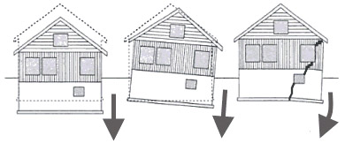
The most important factor is the soil under the foundation, it may not withstand a high load. To avoid this, you need to calculate the total weight of the building, including the foundation.
An example of calculating the weight of a foundation: You want to build a brick building and have chosen a strip foundation for it. The foundation goes deep into the ground below the freezing depth and will have a height of 2 meters.
Then we calculate the length of the entire tape, that is, the perimeter: P \u003d (a + b) * 2 \u003d (5 + 8) * 2 \u003d 26 m, add the length of the inner wall, 5 meters, as a result we get a total foundation length of 31 m.
Next, we calculate the volume, to do this you need to multiply the width of the foundation by the length and height, let's say the width is 50 cm, which means 0.5cm * 31m * 2m = 31 m 2. Reinforced concrete has an area of 2400 kg / m 3, now we find the weight of the foundation structure: 31 m3 * 2400 kg / m = 74 tons 400 kilograms.
The reference area will be 3100*50=15500 cm2. Now we add the weight of the foundation to the weight of the building and divide it by the supporting area, now you have a kilogram load per 1 cm 2.
Well, if, according to your calculations, the maximum load exceeded these types of soils, then we change the size of the foundation in order to increase its bearing area. If you have a strip type of foundation, then you can increase its bearing area by increasing the width, and if you have a columnar type of foundation, then increase the size of the column or their number. But it should be remembered that the total weight of the house will increase from this, so it is recommended to re-calculate.
1 Loads taken into account in the calculation of foundations and
foundations
loads,
on which the basis is calculated
and foundations, determined by the results
calculation that takes into account the joint work
buildings and foundations.
Loads
on the basis it is allowed to determine
without regard to their redistribution
over-foundation structure with
calculations:
4
—
foundations of buildings and structures of the 3rd
class;
—
general stability of the soil mass
grounds jointly by construction;
—
average values of base deformations;
—
deformations of the base in the binding stage
standard design to local ground
conditions.
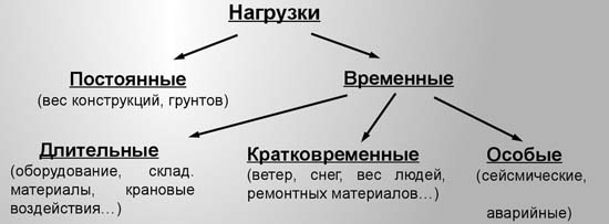
V
depending on duration
load actions distinguish between constant
and temporary (long-term, short-term,
special) loads.
TO
constant loads include mass
parts of the structure, mass and pressure
soils. Permanent loads determine
according to design data based on
geometric dimensions and specific
masses of materials from which they
made.
TO
main types of long-term loads
should include: a lot of temporary
partitions, gravies and footings under
equipment; mass of stationary
equipment; pressure of gases and liquids;
floor loads from stored
materials; loads from people, animals,
equipment for residential flooring;
public and agricultural
buildings with reduced standards
values; vertical loads from
overhead and overhead cranes with reduced
normative values; impact,
caused by deformations of the base,
not accompanied by fundamental change
soil structure, as well as thawing
permafrost soils; snow loads
with a reduced design value,
determined by multiplying the total
calculated value by the coefficient
0.5 starting from the third snow region
and etc.
TO
main types of short-term loads
should be attributed: loads from equipment,
arising in the start-stop,
transitional and test modes,
mass of people, repair materials in
equipment maintenance and repair areas;
loads from people, animals, equipment
on floors of residential, public and
agricultural buildings with complete
normative value; snow loads
with full calculated value; wind
loads; ice loads,
TO
special loads should include:
seismic impacts; explosive
impact; loads caused by sudden
violation of the technological process;
impacts due to deformations
grounds accompanied by root
change in soil structure.
At
calculations of foundations and foundations should
take into account the load from the stored
materials and equipment placed
close to foundations.
At
limit state design
economy and reliability, bearing
ability and normal operation
are provided with calculated coefficients,
which make it possible to take into account separately
features of physical and mechanical properties
base soils,
5
specifics
operating loads, responsibility
and features of design schemes
buildings and structures.
Coefficient
load reliability
takes into account the possibility of accidental
deviations (in the direction of increase) of external
loads in real conditions from loads,
accepted in the project.
Calculations
bases and foundations are produced on
design loads determined
multiplying their normative values by
appropriate safety factors.
V
deformation calculations – group II
limit states
(II
GPS), load safety factor
= 1.
At
calculations for the first group of limit
states (I HMS) for constant loads
values
taken according to table 1; for temporary
loads depending on the type of load
- according to SNiP 2.01.07-85. For some types
live loads values
are given in table 2
T
table 1 - Reliability factors
by load
|
Constructions |
Coefficient on |
|
Designs: metal |
1.05 |
|
Concrete over v on the |
1.1 1.2 1.3 |
|
Soils: v |
1.1 |
|
Bulk |
1.15 |
6
T
table 2 - Reliability factors
by load
|
View |
Coefficient |
|
Temporary 2.0 then snowy wind icy |
1.3 1.2 1.4 1.4 1.3 |
If calculation is required in gigacalories
In the absence of a heat energy meter on an open heating circuit, the calculation of the heat load on the heating of the building is calculated by the formula Q = V * (T1 - T2 ) / 1000, where:
- V - the amount of water consumed by the heating system, calculated in tons or m 3,
- T1 - the number indicating the temperature of hot water is measured in ° C and the temperature corresponding to a certain pressure in the system is taken for calculations. This indicator has its own name - enthalpy. If it is not possible to remove temperature indicators in a practical way, they resort to an average indicator. It is in the range of 60-65 o C.
- T2 - temperature of cold water. It is quite difficult to measure it in the system, therefore, constant indicators have been developed that depend on the temperature regime on the street. For example, in one of the regions, in the cold season, this indicator is taken equal to 5, in summer - 15.
- 1,000 is the coefficient for obtaining the result immediately in gigacalories.
In the case of a closed circuit, the heat load (gcal/h) is calculated differently:
- α is a coefficient designed to correct climatic conditions. It is taken into account if the street temperature differs from -30 ° C;
- V - the volume of the building according to external measurements;
- qO - specific heating index of the building at a given tn.r. \u003d -30 ° C, measured in kcal / m 3 * C;
- tv is the calculated internal temperature in the building;
- tn.r. - estimated street temperature for drafting a heating system;
- Kn.r. is the infiltration coefficient. It is due to the ratio of heat losses of the calculated building with infiltration and heat transfer through external structural elements at the street temperature, which is set within the framework of the project being drawn up.
The calculation of the heat load turns out to be somewhat enlarged, but it is this formula that is given in the technical literature.
Tiled foundation.
The slab foundation is a monolithic structure, poured under the entire area of the building. To make a calculation, you need basic data, that is, area and thickness. Our building has dimensions of 5 by 8 and its area will be 40 m 2. The recommended minimum thickness is 10-15 centimeters, which means that when pouring the foundation, we need 400 m 3 of concrete.
The height of the base plate is equal to the height and width of the stiffener. So if the height of the main plate is 10 cm, then the depth and width of the stiffener will also be 10 cm, it follows that the cross section of 10 cm of the rib will be 0.1 m * 0.1 = 0.01 meters, then multiply the result by 0.01 m, for the entire length of the rib 47 m, we get a volume of 0.41 m 3.
Tiled type of foundation. Quantity of armature and binding wire.
The amount of reinforcement depends on the soil and the weight of the building. Let's say your structure stands on stable ground and is light in weight, then thin fittings with a diameter of 1 centimeter will do. Well, if the construction of the house is heavy and stands on unstable ground, then thicker reinforcement from 14 mm will suit you. The step of the reinforcing cage is at least 20 centimeters.
For example, the foundation of a private building has a length of 8 meters and a width of 5 meters. With a step frequency of 30 centimeters, 27 bars are needed in length and 17 in width. 2 belts are needed, so the number of bars is (30 + 27) * 2 = 114. Now we multiply this number by the length of one bar.
Then we will make a connection at the places of the upper mesh of the reinforcement with the lower mesh, we will do the same at the intersection of the longitudinal and transverse bars. The number of connections will be 27*17= 459.
With a plate thickness of 20 centimeters and a frame distance from the surface of 5 cm, it means that for one connection you need a reinforcement bar 20 cm-10 cm = 10 cm long, and now the total number of connections is 459 * 0.1 m = 45.9 meters of reinforcement.
By the number of intersections of horizontal bars, you can calculate the amount of wire needed. There will be 459 connections on the lower level and the same number on the top level, for a total of 918 connections. To tie one such place, you need a wire that is bent in half, the entire length for one connection is 30 cm, which means 918 m * 0.3 m = 275.4 meters.
General calculation sequence
- Determination of building weight, wind and snow pressures.
- Evaluation of the bearing capacity of the soil.
- Calculation of the mass of the base.
- Comparison of the total load from the mass of the structure and its foundation, the impact of snow and wind with the calculated resistance of the earth.
- Size adjustment (if necessary).
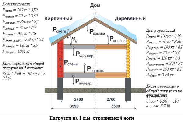
The mass of the building is calculated from its area (Sd). For calculations, the average specific gravity of the roof, walls and ceilings is used, depending on the materials used from the reference tables.
Specific weight of 1 m2 of walls:
| Log ø14-18cm | 100 |
| Expanded clay concrete 35 cm thick | 500 |
| Solid brick 250 mm wide | 500 |
| The same 510 mm | 1000 |
| Sawdust concrete 350 mm thick | 400 |
| Wooden frame 150 mm with insulation | 50 |
| Hollow brick 380 mm wide | 600 |
| The same 510 mm | 750 |
Specific weight of 1 m2 of floors:
| Reinforced concrete hollow slabs | 350 |
| Socle on wooden beams with insulation up to 500 kg/m3 | 300 |
| The same 200 kg/m3 | 150 |
| Attic on wooden beams with insulation up to 500 kg/m3 | 200 |
| Reinforced concrete | 500 |

Specific weight of 1 m2 of roof:
| Sheet steel | 30 |
| Slate | 50 |
| Roof tiles | 80 |
The mass of the building is calculated as the sum of the factors of the building area by the specific gravity of the roof, walls and ceilings. To the resulting weight of the building, it is necessary to add payloads (furniture, people), which are tentatively recommended for residential premises at the rate of 100 kg of mass per 1 m2.
2. Wind load on the foundation.
It is found according to the formula:
W=W∙k, where W=24-120 kg/m2 is the normative value of wind pressure (according to the tables, depending on the region of Russia).
When determining the value of the coefficient k, the type of terrain is taken into account:
- A - flat areas.
- B - there are obstacles 10 m high.
- C - urban areas with a height of >25 m.
Pressure change factor with altitude (k)
| House height, m | A | B | WITH |
| up to 5 | 0,75 | 0,5 | 0,4 |
| 10 | 1,0 | 0,65 | 0,4 |
| 20 | 1,25 | 0,85 | 0,5 |
For high-rise buildings (towers, masts), the calculation is performed taking into account wind pulsations.
3. Snow pressure on the foundation.
It is defined as the product of the roof area by the coefficient of its slope and by the weight of one square meter of snow cover, the value of which depends on the region.
Normative load from snow cover for Russia, kg/m2:
| South | 50 |
| North | 190 |
| middle lane | 100 |
Roof slope influence factor:
| 0-20° | 1,0 |
| 20-30° | 0,8 |
| 30-40° | 0,6 |
| 40-50° | 0,4 |
| 50-60° | 0,2 |
To determine what load falls on the foundation, it is necessary to sum up the static and temporary effects and multiply the result by the safety factor (1.5). Such calculations are easily performed using calculators containing the databases of the necessary data.
4. Bearing capacity of the soil.
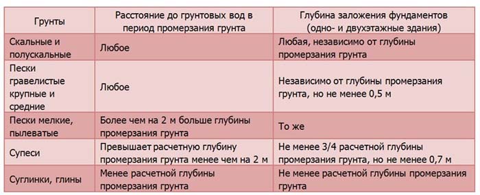
When developing a project, a mandatory procedure is to conduct geological surveys at the construction site. Based on the results of these works, the type of soil is determined, and according to it, the bearing capacity of the reservoir at the depth of the foundation. The latter also depends on the levels of freezing (df) and groundwater occurrence (dw).
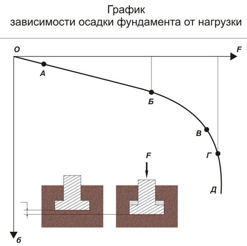
Sole penetration into the ground:
Load safety factor
The second coefficient by which we must multiply all the standard (characteristic) values of loads in order to obtain the calculated values is the load safety factor γf. The essence of this coefficient is that we will never be able to accurately determine the load in a particular situation - and the density of the material may vary, and the thickness of the layers, and the live loads may go beyond the average statistical limits defined by it - in general, the coefficient γf is essentially a safety factor that increases or decreases the load depending on the situation. And the most important thing for us is to determine correctly the design situation in order to choose the right γf.
In order to understand what value of the coefficient γf should be chosen in different cases, you need to learn for yourself the concepts of limiting, operational, quasi-permanent and cyclic load values. So that it doesn’t seem to you that I want to completely confuse you (the DBN “Loads and Impacts” itself does an excellent job with this, you don’t need to make additional efforts), I will immediately greatly simplify the analysis of these concepts. We discard the last two as extremely rare (in terms of endurance, creep, etc.), and remember about the first two:
— the limit value is always used in the calculation for the first limit state (more on limit states here);
— the service value is always used in the design for the second limit state.
For the limit value, the letter “m” is added to the load safety factor - γfm, and for operational - the letter "e" - γfe. The value of the limit value, as a rule, is higher than the operational value, therefore, in the calculation of structures for the first limit state (in terms of strength and stability), the calculated value of the loads will be greater than in the calculation for the second limit state (in terms of deformation and crack resistance).
All values of the coefficients can be selected from the DBN "Loads and Impacts", starting from paragraph 5.1 and up to the end of the document.
Example 1. Determination of the reliability factors for the load.
Let's say we have a load from the weight of a floor slab of 300 kg / m2 and a temporary load from the weight of people in the apartment. We need to determine the limiting and operational value of these loads for the steady state. Liability factor γn determined for class CC2 and category B (see paragraph 1 of this article).
1) The load from the weight of the slab refers to the weight of the structures, the coefficients for it are found from section 5 of the DBN "Loads and effects". From table 5.1 we find γfm = 1.1; γfe = 1,0.
The reliability factor for liability for the calculation of the first limit state is 1.0; for calculation according to the second limit state - 0.975 (see table 5 in paragraph 1 of this article).
Thus, when calculating according to the first limit state, the calculated load from the weight of the slab will be 1.1∙1.0∙300 = 330 kg/m2, and when calculating according to the second limit state - 1.0∙0.975∙300 = 293 kg/m2 .
2) The live load from the weight of people refers to section 6 of the DBN, from table 6.2 we find the standard (characteristic) load value of 150 kg / m2. From clause 6.7 we find the load safety factor for the limit value γfm = 1.3 (for load values less than 200 kg/m2). I did not find the load safety factor for the operational value in Section 6 for uniformly distributed loads, but I allow myself to take it from old memory γfe = 1,0.
The reliability factor for liability for the calculation of the first limit state is 1.0; for calculation according to the second limit state - 0.975 (see table 5 in paragraph 1 of this article).
Thus, when calculating according to the first limit state, the calculated live load will be equal to 1.3∙1.0∙150 = 195 kg/m2, and when calculating according to the second limit state, it will be 1.0∙0.975∙150 = 146 kg/m2.
From example 1, we see that the load values in different parts of the calculation will differ significantly.
When calculating the temporary loads for multi-storey buildings, I recommend not to forget about the reducing factors from paragraph 6.8 of the DBN "Loads and Impacts", they do not allow overruns and bring the calculation model to the most plausible. True, when calculating in software systems, it is necessary to dodge rather well in order to take into account the reduced load only for foundations, columns and beams, while this reduction does not apply to floors.
How to independently calculate the load on the foundation
The purpose of the calculation is to choose the type of foundation and its dimensions. The tasks to be solved for this are: to assess the loads from the structure of the future structure, acting on a unit area of soil; comparison of the obtained results with the bearing capacity of the reservoir at the depth of placement.

- Region (climatic conditions, seismic hazard).
- Information about the type of soil, the level of groundwater at the construction site (it is preferable to obtain such information from the results of geological surveys, but in a preliminary assessment, you can use data on neighboring sites).
- The proposed layout of the future building, the number of floors, the type of roof.
- What building materials will be used for the construction.
The final calculation of the foundation can be performed only after the design and preferably if this is done by a specialized organization. However, a preliminary assessment can be carried out independently in order to determine a suitable location, the amount of required materials and the amount of work. This will increase durability (to prevent deformations of the base and building structures) and reduce costs. Quite simply and conveniently, the problem is solved using online calculators that have become widespread recently.
The first include the total weight of the structure itself.It consists of a mass of walls, foundations, roofing, ceilings, insulation, windows and doors, furniture, household appliances, sewerage, heating, plumbing, decoration, residents. The second type is temporary. These are snowfall, strong winds, seismic impacts.
Wall load
To determine the load from the walls, it is necessary to calculate such parameters as the number of floors, their height, dimensions in the plan. That is, you need to know the length, height and width of all the walls in the house and, by multiplying these data, determine the total volume of the walls in the building. Next, the volume of the building is multiplied by the specific gravity of the material used as walls, according to the table below, and the weight of all the walls of the building is obtained. Then the weight of the building is divided by the area of support of the walls on the foundation.
These actions can be written in the following order:
We determine the area of \u200b\u200bthe walls S \u003d AxB, where S is the area, A is the width, B is the height.
Determine the volume of the walls V=SxT, where V is the volume, S is the area, T is the thickness of the walls.
We determine the weight of the walls Q=Vxg, where Q is the weight, V is the volume, g is the specific gravity of the wall material. We determine the specific load with which the walls of the building press on the foundation (kg / m2) q \u003d Q / s, where s is the area of \u200b\u200bsupport of the supporting structures on the foundation.
Permanent, long-term and short-term loads
The third thing to understand in order to determine the design combination of loads is the concept of permanent, long-term and short-term loads. The fact is that for each type of these loads, different coefficients are used when determining combinations. Therefore, after determining all the loads acting on the building, you should refer to paragraphs 4.11 - 4.13 of the DBN "Loads and Impacts" and make a choice of which type each load belongs to.
Here I want to draw your attention to paragraphs 4.12 (h) and 4.13 (b), as well as to p
4.12 (j) and 4.13 (c).

How can human loads and snow loads be both long-term and short-term at the same time? If you include them in the calculation both there and there, then there will obviously be a bust. And rightly so, you need to make a choice in favor of one of two options: if you consider the structure for creep (for example) and use the standard value of the load with a reduced value (that is, quasi-permanent), then such a live load should be classified as long-term; if you do the usual calculation using the limiting and operational values of the loads, then your live loads in this case are short-term.
Thus, in most cases, loads from people and snow are short-term.
Example 2. Determining the type of loads in the calculation.
The table records the loads collected for the calculation of the building. In the right column, it is necessary to indicate the type of load in accordance with paragraphs 4.11 - 4.13 of the DBN "Loads and Impacts".
|
Load from the weight of structures (ceilings, walls, foundations) |
4.11a |
constant |
|
Load from the weight of interior brick partitions in a residential building |
4.11a |
permanent (although the partitions are considered temporary, in fact they are not demolished in the apartment) |
|
Load from drywall partitions in a studio apartment |
4.12a |
long (these partitions have many chances to change location) |
|
Snow load |
4.13d |
short-term (see explanations above the table) |
|
Live load from the weight of people |
4.13c |
short-term (see explanations above the table) |
|
Load from the weight of the floors in the apartment |
4.11a |
permanent (there is no exact point in DBN, but there will always be floors in the apartment) |
|
Load from the weight of the soil on the edges of the foundation |
4.11b |
constant |
Calculator for calculating the required boiler power
To determine the approximate power, you can know a simple ratio: to heat 10 m2 you need 1 kW of power.
For example, the area of the house is 300 m2, which means that you need to purchase a boiler with a capacity of at least 30 kW.
To calculate the power of a heating boiler for a particular house, you need to enter certain parameters into the calculator, having previously measured the room: indicate the desired temperature in the room, the average air temperature outside in winter, the dimensions of the room (length, height) in meters, the dimensions of windows and doors , indicate the presence of ventilation, type of ceilings, etc.
Then you need to click the "Calculate" button. The calculator will quickly calculate what power boiler is needed to heat the house.
Our online calculator for calculating the power of the boiler provides for the operational reserve of the device, taking into account the specific features of the room. The summation of all the parameters entered in the table leads to the total value of the required power, which the boiler must comply with.