Distance between pipeline supports
The distance between the pipeline supports largely depends on the principle of their operation. According to this criterion, the supports are divided into movable and fixed. On fixed supports, the pipes are fixed without the possibility of displacement, while the structures of movable supports provide the objects fixed on it with some freedom of movement along the guides. This is necessary in areas with strong temperature changes that cause deformation and displacement of pipes.
Movable supports in pipeline structures are:
In the roller bearings for the movement of pipes, special roller blocks are provided. It is advisable to use such supports in the case of high or low supports separated from each other, as well as along the walls of a tunnel or building, using brackets and frames. In this case, the diameter of the pipe Du must be more than 200 mm. If the pipeline is laid in an impassable channel, the use of roller bearings is not possible.
Supports, where nothing but free space is used to move pipes, and the friction force serves as a limiter, are called sliding. When installing pipes with DN values from 25 to 150 mm, sliding supports are preferred for any method of laying the pipeline. If the diameter DN is in the range from 200 to 1200 mm, the use of sliding supports is possible if the section is a semi-passage or non-passage channel, as well as in the case of laying the lower rows in the tunnel.
Laying pipes with a diameter of DN more than 200 mm above the ground using racks provides for the use of both roller and sliding supports.
The use of suspended supports is accepted in conditions of above-ground laying with the use of stretch marks and flyovers. Also, these supports are applicable when a pipe is suspended from a pipe, where self-compensation occurs or U-shaped compensators are installed.
If channelless pipe laying is carried out, or gland expansion joints are used, the use of movable supports is not provided.
How is the required distance between the movable supports established? It is based on calculations of the strength and deflection of pipes. The result is determined by the method of laying, the diameter of the pipes and the parameters of the working environment. Calculation methods are set out in Appendix No. 4 of SNiP 2.04.12-86 "Distance between pipeline supports". The following spans between supports are usually calculated:
maximum span distance based on strength calculation;
maximum span distance based on deflection for straight sections;
recommended distance from one support to another in various sections of the pipeline.
The distances between the fixed supports are determined by the schematic features of a particular pipeline, its working environment and operating mode. Supports must be present near each branch or shut-off section, and in other places they must be placed in accordance with the presence of compensators and self-compensation. The distance between them is determined by the design requirements.
The distance between the pipeline supports is calculated based on the expected external forces and moments. Friction, internal pressure and compensation are taken into account. As well as the weight of the pipeline and the transported substance, dust, wind, ice, etc. If the temperature value is set different from +20 degrees, it is necessary to use special coefficients.
Obviously, with this approach, the calculations will be individual. As an example, we can take the average values of the distances between the supports of uninsulated steel pipes, depending on their diameter:
The values shown for these pipe diameters are maximum values. Based on the calculation methodology, ready-made tables are often used in the design.
The distances between the supports established during the design should not exceed the values obtained from the calculations. However, their reduction is permissible when it comes to installing a support near a branch, a locking device, etc. Additional calculations are required if the pipeline supports are to be installed on foundations.
Enter your name and phone number, click the "Request a callback" button,
and we will quickly call you back to clarify how we can be of service to you
The step of laying a warm water floor
The most remarkable property of a water heated floor, in comparison with other heating systems, is the comfort created in the room due to the formation of an optimal temperature field for a person. Unfortunately, the vast majority of companies involved in the installation of underfloor heating cannot carry out a qualitative calculation of the system, and therefore offer additional heating means in the form of radiators or convectors, even in modern energy-efficient homes. The most important characteristics influencing the efficiency of the system are the laying spacing and the method of laying the underfloor heating pipes. The correct choice of these parameters during design work allows you to significantly increase the efficiency of the heating system and refuse additional heating, thereby retaining the main advantages of a water-heated floor. At the same time, it is necessary to comply with the condition of not exceeding the maximum allowable temperature of the floor surface. Of course, a high-quality heating system project involves the use of high-quality equipment.
The company "Pervoistochnik" is a member of the international group of companies Thermotech and represents the systems of water-heated floor heating of the Swedish manufacturer in Ukraine. Termotech's vast experience in developing new exclusive equipment and designing underfloor heating systems made it possible to install a water heated floor as a complete and unique heating system at thousands of facilities in various countries of Europe and Asia with various climatic conditions.
Therefore, if you are told that it is impossible to heat your house with underfloor heating alone, without the additional use of radiators, convectors or fan coil units, you should think about it. If the house is old and not insulated (heat loss is more than 100 W/m²), this may be the case. But, if the house is built using modern technologies or has at least a slight thermal insulation of the walls and roof, and double-glazed windows are installed in it, you have reason to doubt the competence of the designer. Most likely, this person does not have the necessary knowledge for the qualitative calculation of a water-heated floor.
With proper design of a heating system based on a water-heated floor, a sufficiently large number of tasks related to thermal and hydraulic calculations, as well as the choice of technical solutions and engineering approaches, are solved.
One of the main tasks is the choice of the type of system (concrete or flooring), as well as the method and step of laying the pipes of the water floor heating circuits. It is these parameters that determine the possibility of using a warm floor as a complete single heating system in a particular room. The choice of these parameters is carried out taking into account the purpose of the room and the amount of heat loss.
Features and scope of copper pipeline
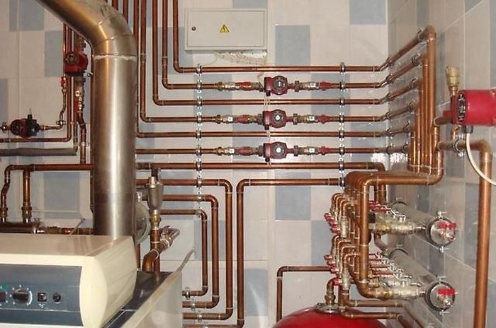
Copper pipes are widely used in engineering systems of residential and industrial premises. One of the advantages of these products over others is their good resistance to high temperatures, UV radiation and corrosion. Do-it-yourself copper pipe laying becomes easier due to the fact that they easily bend at any angle.
The disadvantages are often considered the high cost of the material, however, the undeniable advantages and possibilities are worth it. Installation of copper pipes is carried out using various fittings.Depending on what kind of connection you need to create, detachable or one-piece, use crimp or solder fittings, respectively. There are a wide variety of shaped materials on the market (for example, from Rehau), thanks to which laying pipes with your own hands becomes easier.
Due to the fact that the copper pipeline has a low linear expansion and operating temperature from -200°С to +250°С, its installation is carried out to create systems:
- Plumbing;
- heating;
- Gas transportation;
- Conditioning;
- Heliosystem.
As a rule, steel pipelines are used for sewer systems.
Installation of copper pipes for the water supply system is carried out in accordance with the norms of SNiP. This material has excellent performance in operation: no silting or overgrowth of the internal section, high resistance to chlorine-containing compounds (which is what our plumbing system “sins” in excess). In addition, this very chlorine creates a thin protective layer on the inner copper surface, thereby ensuring a long service life of the water supply system. And the water itself is saturated, released at the same time, useful for human health copper.
Data for calculating the length of the pipeline
In order to calculate the length of pipelines for a certain space of the room, the following data will be needed: the diameter of the coolant, the step of laying the floor heating pipe, the heated surface.
Pipe length for circuit
The length of the coolant directly depends on the outer diameter of the pipe. Therefore, if you miss this moment of calculation at the initial stage, there will be difficulties with the circulation of water, which in turn will lead to poor-quality floor heating. It is possible to consider the permissible cross-sectional norms of the underfloor heating pipe and its length according to the following scheme.
| Outside pipe diameter | Maximum pipe size |
| 1.6 - 1.7 cm. | 100 - 102 m. |
| 1.8 - 1.9 cm. | 120 - 122m. |
| 2 cm | 120 - 125 m. |
But since the circuit must be made of solid material, the number of circuits for the heating area will be affected by the step of laying the water-heated floor.
Underfloor heating step
Not only the length of the pipeline, but also the heat transfer power will depend on the laying step. Therefore, with the correct installation of heat carriers, it will be possible to save on the energy consumption of underfloor heating.
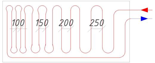
The recommended step for laying underfloor heating pipes is considered to be 20 cm. This indicator is due to the fact that when it is used, the floor is evenly heated, and installation work is also simplified. In addition to this indicator, the following norms are also allowed: 10 cm. 15 cm. 25 cm and 30 cm.
Let's give a clear example, the flow rate of the pipeline at the optimal step of the warm floor.
| step, see | Consumption of working material per 1 sq.m., m. |
| 10 — 12 | 10 – 10,5 |
| 15 — 18 | 6,7 – 7,2 |
| 20 — 22 | 5 – 6,1 |
| 25 — 27 | 4 – 4,8 |
| 30 — 35 | 3,4 – 3,9 |
With a denser laying, the turns of the product will be loop-shaped, which will complicate the circulation of the coolant. And with a larger installation step, the heating of the room will not be uniform.
Online calculator for calculation
Since the contour of the warm floor should capture the total area of \u200b\u200bthe room as much as possible, it is necessary to draw up a diagram of its location. To do this, you need a millimeter sheet of paper and a pencil. The scheme is drawn up in the following order:
- On paper, the total area of \u200b\u200bthe room is drawn.
- The dimensions of overall furniture and floor electrical equipment are measured.
- In the appropriate arrangement, all measurements are transferred to paper.
- It is strictly forbidden for the coolant to pass close to the walls, therefore, an indent of 20 cm is made along the entire drawn area.

By shading all the applied measurements and indents, you can visually calculate the area of \u200b\u200bthe room where the coolants will be located.
So, knowing all the necessary data, you can proceed to the direct calculation of the working material of the heating system.
The length is calculated using the following formula:
D = P/T ˟ k, where:
D - pipe length;
P is the heated area of the room;
T - pipe pitch for a warm water floor;
k is the reserve indicator, which is in the range of 1.1-1.4.
The main parameters affecting the determination of the pipe layout step
The distance between the pipes of the underfloor heating is determined based on the following parameters, which are the main ones:
- room area;
- type and diameter of pipes used in the heating system;
Determining the area of a room
To calculate the pitch of the underfloor heating pipe depending on the area of \u200b\u200bthe room, it is necessary at the initial stage to determine the area itself. You can calculate using the simplest geometric formula:
Area = width * length.
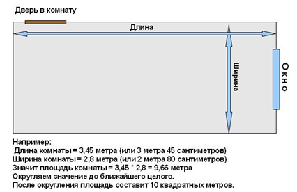
How to independently calculate the area of \u200b\u200ba heated room
Experts recommend reducing the resulting figure by the area occupied by large furniture. Heating the floor under the furniture is not advisable, as it can lead to deformation, and reducing the area will save the money required for arranging the floor.
Taking into account the results obtained, it is possible to determine the most optimal step for laying the turns of the pipeline.
View Influence
The pitch of the pipes of a water-heated floor is also determined based on the material of the product, or rather, on the coefficient of its thermal conductivity, and the diameter of the pipe.
Copper and corrugated stainless pipes have the highest coefficient value. Further, the decrease of the considered parameter occurs according to the following scheme:
- metal-plastic;
- polyethylene;
- polypropylene.
That is, polypropylene pipes have the lowest heat transfer coefficient, which are recommended to be used to organize a heating system only in exceptional cases.
The higher the heat transfer coefficient, the greater the distance pipes can be laid and vice versa. Thus, the smaller diameter pipes are used, the smaller the laying step should be.
The relationship between step and coolant temperature is shown in the table.
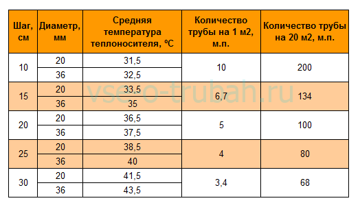
Determination of the number of pipes depending on the diameter
For a certain pipe diameter, the laying step should be the higher, the higher the average temperature of the coolant in the system.
The most popular are pipes with a diameter of 16 mm. At the same time, the laying pitch is 250 mm - 300 mm in the living room, 100 mm - 150 mm in the bathroom and 300 mm - 350 mm in other premises.
What you need to know and consider in order to make a floor heating scheme
Since this is not the first step in designing a warm floor, we have collected some data that will help in drawing a floor heating layout.
- the location of the collector. In my case:
- the number of underfloor heating branches, respectively, the number of outlets on the collectors. I have 5;
is the average length of the branches. I have 60.
You collect your values obtained when calculating pipes for a warm floor.
You also need to consider the following:
- the lengths of the branches should be approximately the same, plus or minus 10%. This is to ensure that the same ducts pass through each branch. (For those who have forgotten: 10% is a tenth, so, from my 60 m it is 6 m. That is, if my underfloor heating branches are all of different lengths, but differ by no more than 6 m, then I will consider that they are the same.)
- branch pipes should not intersect and should not lie on top of each other.
How many pipes are required
When the choice of parts from which the installation of a water-heated floor will be installed is completed, they begin to calculate the required number of pipes for the pipeline. The consumption of building materials is usually calculated in several steps:

To achieve optimal pipeline performance, the layout of the circuits should not exceed 6 meters, otherwise the water will cool quickly. If the room is too large, then it would be logical to divide it into sectors, each of which will have a separate circuit. This method of installation allows you to make the heating more uniform.
Biofilm has formed in the factory
The biofilm acts as an insulation and underfloor heating does not heat up. In this case, your heating engineer will take over the plant with suitable training. Too low heat consumption. If set too low, the heating will not have enough heat. You can measure the supply and return temperatures. The difference is ideally created by releasing heat into the room. However, heat losses must always be planned. The floor heating does not heat up if the supply temperature is set too low.
How to make a floor with water heating with your own hands
Heated the floor with electricity or water. Both methods are imperfect, and have pros and cons. Read more about electric heating here. and in this article we will talk about how to make a warm floor with water and pipes.
How to heat the floor with water
Water-heated floor #8212 is a rather complicated design to implement, but it is comfortable and gives a feeling of coziness, moreover, it is economical in use (but not in installation). The whole idea is that pipes are hidden under the floor or its covering, through which water / antifreeze / ethylene glycol, etc. circulate. (depending on the pipes and the desire of the owner). The length of the pipes of the water floor can be quite large, therefore, to ensure the normal circulation of the coolant, a pump is required. Read more about choosing and installing a pump in a water heated floor system here.
The coolant is heated in two ways:
- hot water boiler
- comes from the centralized heating system.
An approximate scheme for organizing water heating from a boiler
To achieve the desired temperature, before being supplied to the pipes, the hot coolant is mixed in the mixing unit with cooled water from the "return" until the required temperature is obtained, and then enters the floor heating pipes through the collector. An exception to this rule can be #8212 condensing boilers, they show their maximum efficiency for such systems with low temperatures. Therefore, if you decide to make a water heated floor with your own hands, consider installing a condensing boiler. This is the whole mechanics of the operation of a water heated floor, but there are some technological nuances that increase its comfort and simplify adjustment.
In order to be able to maintain a comfortable temperature of the warm floor, there is a special device #8212 thermostat, or as it is also called a thermostat. This device, using sensors, controls the temperature of the floor and the temperature of the coolant. According to their readings and the set temperature (you set it yourself on the control panel), it regulates the operation of the mixing unit, increasing / lowering the temperature of the flowing coolant. If the collector unit is equipped with thermostatic regulators at each inlet, a thermostat for a water-heated floor is optional, but it creates very comfortable conditions: the floor under your feet is always at a predetermined temperature. Read more about thermostats and their installation here.
In the simplest version, the connection diagram for a warm water floor looks like this
#171 Pie#187
Device #171 pirogue #187 water floor heating
A damper tape is rolled around the perimeter of the room or a tape heat-insulating material is laid, you can use polystyrene cut into strips 10 cm wide, polystyrene foam or other sheet insulation (about 10 mm thick), you can also use mineral wool cardboard.
This measure is needed, firstly, so that due to thermal expansion, cracks do not occur along the perimeter of the floor, and also in order to reduce heat loss through the walls and foundation.
Next, pipes are laid on the thermal insulation (the choice of pipes for a warm water floor is written in this article). There are the following ways to fix the floor heating pipe:
A metal mesh is laid on the heat insulator with a step of 5 or 10 cm (this step is convenient for laying).Pipes are attached to its rods with ordinary plastic clamps or wire.
Methods for attaching pipes for a water floor can be different.
The heat-insulating substrate is used with markings (mesh) applied to it, for example, from Valtec. Then, in the right places, fasteners are hammered into the floor, into which the pipe is then inserted.
Distance from the water supply to the foundation of structures
If the water supply has to be carried out in closed conditions, it is permissible to reduce the distance from the foundation to 1.5 m, a pipeline made of polymers is usually used, it is placed in a casing above 0.5 m of the level of the foundation sole.
When installing a water supply system, the following minimum tolerances to foundation slabs and networks are taken:
- architectural structures - 5 m;
- fences of industrial buildings, flyovers, supporting structures of contact electrical networks and communications, rail tracks - 3 m;
- railways with a gauge of 1520 mm not less than the depth of the trench to the base of the embankment and the edge of the excavation - 4 m;
- rail tracks with a gauge of 750 mm - 2.8 m;
- street boards on the edge of roads or roadside - 2 m;
- cuvette edge or the sole of the road embankment - 1 m;
- power transmission towers: - with voltage up to 1 kV. (conductors of street lighting, electric contact lines of urban electric transport) - 1 m; – from 1 to 35 kV. - 2 m; - from 35 to 110 kW and more - 3 m.
- lining of deepened cast-iron tubings of the metro - 5 m;
- lining of concrete materials placed below 20 m of the soil surface - 5 m.
- lining of metro structures without hydraulic insulation - 8 m.
The building codes indicate the distances to the central axis of trees with a crown circumference of less than 5 m - in this case, the water supply system is laid underground from the axis by at least 2 m.

Rice. 5 Standards for distances between communications underground
Minimum distance between welds
The distance between welds in metal structures is determined under different conditions. Below are the main examples with distance restrictions.
| Type of seams and objects near which they are located | Determining the minimum distance |
| The distance between the axes of the seams, which are in the neighborhood, but do not mate with each other. | Not less than the nominal thickness of the parts to be welded. If the wall is more than 8 mm, then the distance should be from 10 cm and above. With the minimum dimensions of the workpiece, the distance should be at least 5 cm. |
| The distance from the rounding of the bottom of the workpiece to the axis of the butt weld. | It does not take into account the exact dimensions, but the possibility of subsequently conducting control using ultrasound. |
| Welded joints in boilers. | When located in boilers, welds should not reach the supports and come into contact with them. There are also no exact data here, but the distance should allow you to monitor the state of the boiler during operation and not interfere with quality control. |
| Distance from holes to weld. | This includes holes for welding or flaring. This distance should not exceed 0.9 of the diameter of the hole itself. |
| Distance from the weld to the tie-in. | Here, on average, a distance of about 5 cm is left. If we are talking about large diameters, then it can change upwards. |
| The distance between adjacent seams at the holes. | The minimum distance should be from 1.4 diameters. |
There are rules that allow you to place the seams at a shorter distance, which will be less than 0.9 of the diameter of the hole itself. This applies to those cases when it is planned to weld fittings and pipes. There are certain conditions for all this. For example, before drilling holes, welded joints must be subjected to radiographic analysis. Ultrasonic testing can also be used instead. The calculation of the allowance will be carried out at a distance of at least one square root of the diameter. It is necessary to make a preliminary calculation, which should show whether the product meets the specified strength parameters.
Minimum distance between pipeline welds
The minimum distance between the welds of the heating network pipeline is also regulated by certain documents. Taking into account the fact that the repair of pipes and the installation of pipelines by welding is more often carried out by specialists who work with critical structures, compliance with the standards is more relevant here.
|
Type of seams and objects near which they are located |
Determining the minimum distance |
| Welding near transverse spiral, circumferential and longitudinal seams of any elements, with the exception of cathode leads. | Here you need to follow the rules very strictly, since this is strictly prohibited. Only if there are cathode leads provided for by the projects, the minimum distance between the seams should be at least 10 cm. |
| Distance between process pipeline welds. | It is calculated according to the wall thickness of the pipe itself. The minimum distance between seams for pipes with a wall thickness up to 3 mm is 3 times the pipe wall thickness. If its size is above 3 mm, then a distance of two pipe wall thicknesses between the seams is allowed. |
| Seam distance from pipe bend. | If you have to work with a pipe that has a bend, then the distance from the seam to the bend should be at least half the diameter of the pipe itself. |
The calculations of the pipeline itself are carried out in advance so that all bends, additional connections and other nuances of the structures comply with the accepted rules. During repairs, errors are often made and the rules are not always followed, but this does not guarantee that the seam made will last a long time. After all, all tolerances for the distances between the seams are taken on the basis of the experience of previous work. The minimum distance between the welds of the pipeline is determined in accordance with GOST 32569-2013. All data regarding the operation, installation and repair of technological pipelines are indicated here.
Conclusion
The relevance of observing distances most of all concerns critical structures that are carried out using certain technologies. Most people who only weld at home may not even have heard of such restrictions. For professionals working with a specific technical task, where all the rules must be strictly observed, the calculation of the minimum distance is mandatory.