Purpose of the main gas pipeline

A main gas pipeline is a pipeline designed to deliver gas from a field or processing area to a place of consumption, or a system of pipes connecting individual gas fields. It belongs to the Unified Gas Supply System of Russia and is one of the key elements of the gas transportation system.
A pipeline connected to a main gas pipeline and designed to transfer part of the gas to specific settlements or enterprises is called a branch.
Natural or associated petroleum hydrocarbon gas (from fields) or liquefied hydrocarbon gases (from production sites) can be transported through such a gas pipeline.
Main pipelines can be:
- single-strand, i.e. with pipes of equal diameter along the entire length of the system;
- multi-thread, which is a system where several more are located parallel to the main branch;
- telescopic, i.e., the diameter of the pipes varies from the head structures to the final gas distribution station.
The diameter of the gas pipeline pipes ranges from 720 mm to 1420 mm. The throughput capacity of the gas pipeline is 30-35 billion cubic meters. m of gas per year.
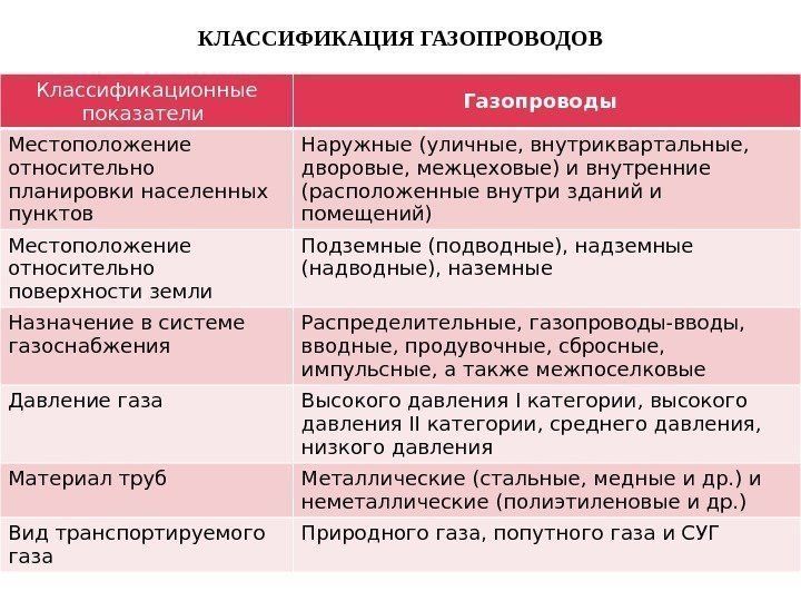 Classification of gas pipelines
- underground (with a distance of 0.8–1 m to the main throughput pipe);
- elevated (i.e., pipes are installed on supports);
- ground (i.e., in bulk dams).
If gas needs to be transported from subsea production sites to shore, then subsea gas pipelines are constructed.
A state-owned company is usually responsible for managing Russian gas transmission systems. It is obliged to check the condition of the pipes, hire workers and monitor the improvement of their qualifications.
Gas pipeline crossings through water
Main gas pipelines can pass above and below water.
Underwater crossings are located perpendicular to the axis of the water flow. At the same time, they are located at a distance of at least half a meter from the mark of possible erosion of the bottom to the surface of the route; they must be separated from the design marks by a distance of at least one meter.
To prevent the pipes from floating up, during construction they are fixed with the help of special weights, poured with concrete or covered with mineral materials.
Sections of crossings passing through natural or artificial obstacles must comply with the standards. This guarantees their safety and reliability in use.
Overhead crossings are needed where the gas pipeline passes through ravines, small rivers, etc. Elements located on the surface are of the following types:
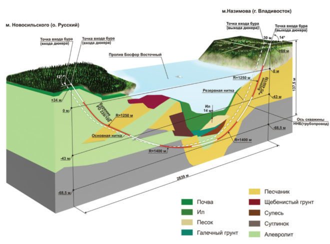 Gas pipeline through water
- arched;
- beam;
- hanging.
The type of above-ground elements is selected depending on the conditions of the place where the main gas pipeline is laid. Arch type walkways are rigid structures and are typically built where pipes pass through channels. The beam structure is a self-supporting pipe.
Hanging transitions are divided into cable-stayed, sagging and flexible. In cable-stayed crossings, inclined cables are responsible for securing the pipeline in the required position. In hanging-type crossings, the gas pipeline is not held by anything and freely bends under its own weight. A flexible transition is a structure in which the pipes are fixed by a suspension system to one or more cables.
Restrictions on the use of polymer pipes
Despite the great demand and advantages of polymer pipes, there are limitations to their use, namely the following:
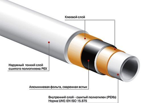 Polyethylene pipe
- In climatic regions where the ambient temperature can drop to -45 degrees Celsius.
- When transporting liquefied gas.
- In areas where the amplitude of the earthquake can exceed seven points.
- In the case of installation of aboveground gas pipelines.
- When passing a gas structure over road or railway tracks.
- When laying gas pipelines transporting gas of external and internal type.
In cases where it is impossible to install polymer pipes, steel pipes are used. When all requirements for operation are observed, they are durable and have a long service life. Steel pipes can be used for any method of laying gas pipelines.
Features of buildings
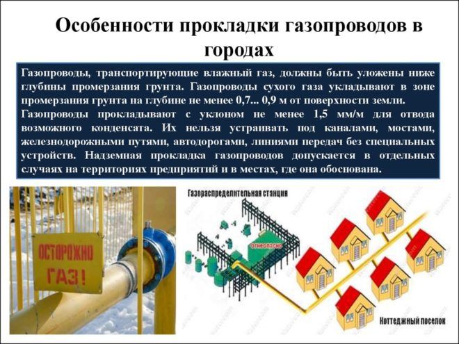 Features of laying gas pipelines in cities
The frame of the station building is a lightweight steel structure. Its roof and walls are made of lightweight panels with two or three layers. In the second version, the parts are equipped with a special frame-frame, which is covered on both sides with zinc, asbestos-cement or aluminum sheets.
According to the level of pressure in the collectors, the stations can operate according to plans that include from one to three superchargers installed one after another, which can also be connected in groups of several elements.
Related video: Tapping under pressure into the main gas pipeline
https://youtube.com/watch?v=EVrFll2aAqo
A selection of questions
- Mikhail, Lipetsk — What discs for metal cutting should be used?
- Ivan, Moscow — What is the GOST of metal-rolled sheet steel?
- Maksim, Tver — What are the best racks for storing rolled metal products?
- Vladimir, Novosibirsk — What does ultrasonic processing of metals mean without the use of abrasive substances?
- Valery, Moscow — How to forge a knife from a bearing with your own hands?
- Stanislav, Voronezh — What equipment is used for the production of galvanized steel air ducts?
Laying of aboveground gas pipelines
The cost of laying a ground gas pipeline is significantly lower than the underground method. With this installation option, the pipes are laid on special supports. Above ground gas pipelines are convenient for inspection and repair, less dangerous in case of gas leakage and in terms of gas entering the premises. It should be borne in mind that the pipes must be protected as much as possible from deformation and damage as a result of corrosion, temperature extremes, and mechanical loads of various origins. The type of protection is selected depending on the climate conditions in a particular region.
First of all, certain distances above the ground and between the supports are established.
 Scheme of laying aboveground gas pipelines
The distance above the ground should be:
- in places of passage of people not less than 2.2 m;
- 5 m - above highways;
- at least 7.1–7.3 m above tram and trolleybus tracks.
The spacing between the supports depends on the diameter of the pipe:
- the maximum allowable distance is 100 m if the pipe diameter does not exceed 30 cm;
- 200 m with a diameter of up to 60 cm;
- 300 m over 60 cm.
The wall thickness of the pipe is taken into account, it must be at least 2 mm.
Designation of gas pipelines
In Russia, each gas pipeline must be marked with a special sign. The installation of signs must be formalized by a joint act of the land user of the enterprise using the main pipeline.
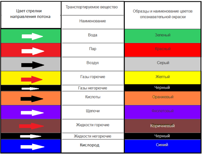 GOST marking of pipelines
Signs are part of the main gas pipeline complex and are an important part of it. They serve as a guide to pipeline detection.
Thanks to them, during work in the buffer zone, you can see the territory through which the pipes pass. Signs show that the enterprise operates according to the norms of main pipelines.
The sign contains warnings and information about the main gas pipeline. It is a pillar with two posters.
On one, located perpendicular to the surface, there is information about the width of the protected area, the location and depth of the pipes, and additional technical parameters. The second shows the distance in kilometers along the entire length of the pipes.It is designed to detect a gas pipeline from the air, therefore it is located with a slight slope (up to 30 degrees).
Blocks, nodes, devices GDS
The composition of the equipment at the gas distribution station must comply with the design and passports of manufacturers.
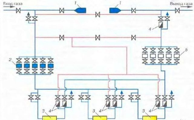
Figure 1 shows the technological scheme of the GDS, where the main units of the GDS are indicated, each of which has its own purpose.
The main nodes of the GDS:
- 1. switch node;
- 2. gas purification unit;
- 3. heating unit;
- 4. reduction unit;
- 5. gas metering unit;
- 6. gas odorization unit.
The GDS switching unit is designed to switch the high-pressure gas flow from automatic to manual pressure control along the bypass line, as well as to prevent pressure increase in the gas supply line to the consumer using safety valves.
The GDS gas purification unit is designed to prevent the ingress of mechanical (solid and liquid) impurities into the technological and gas control equipment and control and automation equipment of the GDS and the consumer.
The hydrate formation prevention unit is designed to prevent freezing of fittings and the formation of crystalline hydrates in gas pipelines and fittings.
The gas reduction unit is designed to reduce and automatically maintain the set gas pressure supplied to the consumer.
The gas metering unit is designed to account for the amount of gas consumption using various flow meters and meters.
The gas odorization unit is designed to add substances with a sharp unpleasant odor (odorants) to the gas. This allows timely detection of gas leaks by smell without special equipment.
Block (node) switching
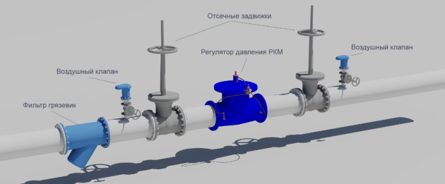
The switching unit is designed to protect the consumer's gas pipeline system from possible high gas pressure and to supply gas to the consumer, bypassing the gas distribution station, via a (bypass) bypass line using manual gas pressure control during repair and maintenance work at the station. The switching unit consists of valves on the inlet and outlet gas pipelines, a bypass line and safety valves.
Bypass line - to switch the flow of high pressure gas from automatic to manual pressure control. The normal position of the shut-off valves on the bypass line is closed. The taps of the bypass line must be sealed by the GDS service. The bypass line must be connected to the outlet gas pipeline before the odorizer (along the gas flow). On the bypass line there are two shut-off bodies: the first one along the gas flow is a shut-off valve; the second is for throttling, a regulator valve.
Safety valves. The safety valve is an automatic pressure relief device actuated by static pressure that occurs in front of the valve, and is characterized by a rapid full lift of the spool due to the dynamic action of the jet of discharged medium exiting the nozzle.
Safety valves are most often used to protect the vessels of apparatuses, tanks, pipelines and other process equipment in case of excessive pressure. The safety valve ensures the safe operation of the equipment in conditions of elevated gas or liquid pressures.
When the pressure in the system rises above the permissible value, the safety valve automatically opens and discharges the necessary excess of the working medium, thereby preventing the possibility of an accident. After the end of the discharge, the pressure decreases to a value less than the beginning of the valve operation, the safety valve closes automatically and remains closed until the pressure in the system again increases above the allowable one.
The main characteristic of safety valves is their capacity, which is determined by the amount of liquid discharged per unit time with the valve open.
The switching node should be located, as a rule, in a separate building or under a canopy that protects the node from precipitation.
The normal position of the shut-off valves on the bypass line is closed. The taps of the bypass line must be sealed by the GDS service.
The working position of the three-way valve installed in front of the safety valves is open.
During operation, safety valves should be tested for operation once a month, and in winter at least once every 10 days, with an entry in the operational log.
Checking and adjustment of safety valves should be carried out at least twice a year in accordance with the schedule. PPK setting limits - 10% above nominal pressure
Checking and adjusting the valves must be documented in the relevant act, the valves are sealed and tagged with the date of verification and adjustment data
In the winter period of operation, the passages to the fittings, instruments, the switching unit must be cleared of snow.
Safety precautions during the operation of the main gas pipeline
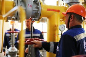 Observe the safety regulations in the areas where the main gas pipeline is being installed
The main pipeline is a potentially dangerous structure, which can only be used in accordance with special instructions governing the construction and operation of main gas pipelines.
The work of the gas pipeline is obliged to monitor the industrial organizations using it. They must also have a special passport in duplicate. They are accompanied by a diagram on which all pipeline parts are applied, their type, manufacturer, material, installed fittings are indicated.
The frequency of bypassing or flying over the entire territory of the structure is established depending on the maintenance standards. In the event of a natural disaster that could damage the pipes, an extraordinary inspection should be carried out. Inspection of pipeline crossings through motor roads is carried out annually.
Performance of main gas pipelines
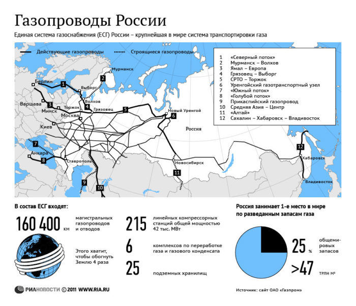 Gas pipelines in Russia
The productivity of a gas pipeline is understood as the amount of gas that is transported through its pipes per year.
Russian gas pipelines differ in performance. The value depends on the fuel and energy balance of the area where the pipe laying is planned. Due to temperature fluctuations, different amounts of gas are used throughout the year, so the actual throughput is usually less important than the calculated one.
To significantly increase the productivity of the main pipeline, centrifugal compressors are installed at compressor stations, powered by gas turbines or electric motors.
To select a system for automatic control of pipeline performance, it is necessary to study transient processes in systems that are responsible for long-distance gas transmission. Transient processes in gas pipelines should not be uncontrolled. When an automatic control system is installed, these processes are usually characterized by attenuation.
Compressor stations
Compressor stations are needed to maintain the pressure level and transport the required volume of gas through the pipeline. There, the gas undergoes purification from foreign substances, dehumidification, pressurization and cooling. After processing, the gas under a certain pressure returns to the gas pipeline.
Compressor stations, along with gas distribution stations and points, are included in the complex of surface structures of the main gas pipeline.
Compressor units are transported to the construction site in the form of blocks completely ready for assembly. They are built at a distance of about 125 kilometers from each other.
The compressor complex includes:
 Compressor station of main gas pipelines
- the station itself
- repair and maintenance and service and maintenance units;
- the area where the dust collectors are located;
- cooling tower;
- water container;
- oil economy;
- gas-cooled devices, etc.
A residential settlement is usually erected next to the compression plant.
Such stations are considered a separate type of man-made impact on the natural environment. Studies have shown that the concentration of nitrogen oxide in the air on the territory of compressor installations exceeds the maximum allowable level.
They are also a powerful source of noise. Scientists have found that prolonged exposure to noise from the compressor station causes disturbances in the human body, and, as a result, causes various diseases and can lead to disability. In addition, noise forces animals and birds to move to new habitats, which leads to their overcrowding and a decrease in the productivity of hunting grounds.
 Safety system installation unit
Hydraulic calculation of low and high pressure
Hydraulic calculation of the low pressure network. When calculating a low-pressure multi-ring distribution network, it is assumed that gas is continuously taken from the network, therefore, the gas flow rate at each section will be equal to the product of the specific flow rate by the length of the section. To take into account the nutritional conditions of the site and the number of storeys of the building, coefficients K are introducedh and Kwellthat are accepted: Kh\u003d 1.0 with two-way power, Kh\u003d 0.5 with one-way power and Kh=0 for hops. K factorwell accepted according to .
Reduced section length (letc) is determined by the formula:
, m
Travel gas consumption is equal to:
, m3/h
where is the specific gas consumption in the area.
Estimated gas consumption at the site:
, m3/h
where is the transit gas consumption, equal to the sum of travel and transit gas costs of subsequent sections;
— equivalent gas consumption, equal to half of the travel gas consumption.
Table 3 - Gas consumption in sections of the distribution network of low-pressure gas pipelines
|
plot number |
Actual length, m |
Power Condition |
Gas consumption, m3/h |
|||
|
track |
equivalent |
transit |
estimated |
|||
|
1-2 |
50 |
Transit |
921,32 |
921,32 |
||
|
2-3 |
480 |
Double Art. |
125,76 |
62,88 |
107,94 |
170,82 |
|
3-4 |
370 |
Single |
59,94 |
29,97 |
29,97 |
|
|
4-5 |
680 |
Single |
110,16 |
55,08 |
55,08 |
|
|
5-6 |
400 |
Single |
50,80 |
25,40 |
25,40 |
|
|
6-7 |
350 |
Gran. |
78,40 |
39,20 |
39,20 |
|
|
7-8 |
350 |
Double Art. |
93,45 |
46,73 |
244,14 |
290,87 |
|
8-9 |
530 |
Double Art. |
127,2 |
63,60 |
63,60 |
|
|
9-10 |
470 |
Single |
65,80 |
32,90 |
32,90 |
|
|
10-7 |
540 |
Gran. |
132,84 |
66,42 |
32,90 |
99,32 |
|
3-9 |
480 |
Single |
48,00 |
24,00 |
24 |
|
|
8-5 |
350 |
Double Art. |
101,15 |
50,58 |
160,96 |
211,54 |
|
2-8 |
70 |
Double Art. |
18,34 |
9,17 |
726,90 |
736,07 |
In accordance with the estimated gas flow rates, we select the pipe diameters in individual sections according to nomograms for calculating low-pressure gas pipelines so that the total pressure losses from hydraulic fracturing to each zero point in each direction would be approximately equal to each other (the discrepancy should be 10%). SNiP recommends pressure losses in sections of the distribution gas pipeline in the amount of . To select the diameter, the value of the average specific pressure losses in each direction from hydraulic fracturing to the "zero" point is used: Pressure losses in local resistances are taken into account by increasing the effective length by 5-10%.
When calculating pressure losses in the section, friction pressure losses and pressure losses in local resistances are taken into account. In the presence of vertical sections or sharp elevation changes on the low pressure gas pipeline, hydrostatic head must also be taken into account. Due to the fact that gas distribution networks are long structures with a relatively small number of local resistances, SNiP allows taking into account pressure losses in local resistances by increasing the estimated length of sections by 5-10%.
Hydraulic calculation of the high pressure network. The reserve jumper on the network is used to provide gas to consumers in emergency conditions, in case of disruption of the normal operation of the network.
In order to save pipe material, a consumer safety factor in an emergency is introduced, i.e. in emergency mode, deterioration of gas supply to all or part of consumers is allowed.
This means that the consumers connected to the emergency half ring are supplied with gas by half in case of an accident. The hydraulic calculation considers the two most unfavorable emergency modes (when the sections adjacent directly to the flow separation point after the GDS are turned off) and one operating mode corresponding to the maximum hourly estimated gas flow rates.
There is no rationing of pressure losses for high and medium pressure networks, these losses are usually accepted within the limits determined by the pressure drop for the selected category of gas pipelines, taking into account the stable operation of the pressure regulator for consumers (minimum 0.20.25 MPa). We assume that a high-pressure network is selected and the gas pressure in the network decreases from 0.6 to 0.3 MPa (g) or from 0.7 to 0.4 MPa (abs.).
Table 5 - Estimated flow rates of high pressure gas
|
plot number |
1st emergency mode |
2nd emergency mode |
Working (normal) mode |
|
GDS-1 |
7643,2 |
7780,3 |
10282,5 |
|
1-2 |
— |
7780,3 |
5107,2 |
|
2-3 |
147,8 |
7484,7 |
4811,64 |
|
3-4 |
660,0 |
6460,3 |
3787,2 |
|
4-5 |
2553,6 |
2673,1 |
— |
|
5-6 |
2639,1 |
2502,1 |
171,0 |
|
6-7 |
3560,4 |
2041,4 |
1092,33 |
|
7-8 |
3856,0 |
1893,6 |
1387,89 |
|
1-8 |
7643,2 |
— |
5175,09 |
The calculation of high-pressure gas pipelines is carried out taking into account the density of the gas when the pressure changes according to nomograms, taking into account the quadratic pressure loss:
, , (19)
where , - gas pressure, respectively, at the beginning and end of the calculated section, MPa;
- the estimated length of the section.