Tube furnace size selection
Purpose: to select a furnace that satisfies the initial data and previously calculated parameters, and to get acquainted with its characteristics and design.
The choice of the standard size of the tube furnace is carried out according to the catalog, depending on its purpose, heat output and type of fuel used.
In our case, the purpose of the furnace is heating and partial evaporation of oil, heat output QT is 36.44 MW, and the fuel is fuel oil. Based on these conditions, we select a tube furnace for combined fuel (fuel oil + gas) SKG1.
Table 2.
Technical characteristics of the furnace SKG1.
|
Indicator |
Meaning |
|
Radiant pipes: heating surface, m2 working length, m |
730 18 |
|
Number of middle sections n |
7 |
|
Heat output, MW (Gcal/h) |
39,5 (34,1) |
|
Permissible thermal stress of radiant pipes, kW/m2 (Mcal/m2h) |
40,6 (35) |
|
Overall dimensions (with service platforms), m: length L width height |
24,44 6 22 |
|
Weight, t: furnace metal (without coil) linings |
113,8 197 |
Furnaces of the SKG1 type are free vertical flame combustion furnaces, box-shaped, with a horizontal arrangement of coil tubes in one radiation chamber. Burners of the GGM-5 or GP type are located in one row in the furnace bottom. On each side of the radiation chamber, single-row wall-mounted tube screens are installed, which are irradiated by a number of vertical torches. The pipe screen can be single-row and double-row wall-mounted.
Since combined fuel is burned in the furnace, a gas collector is provided on the furnace, through which the combustion gases are discharged into a separate chimney.
The burners are serviced from one side of the furnace, due to which two single-chamber furnaces can be installed side by side on a common foundation, connected by a landing, and thus form a kind of two-chamber furnace.
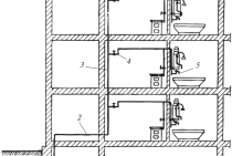
The design of the SKG1 type furnace is shown in Fig.2.
Fig.2. Tube furnace type SKG1:
1 - landings; 2 - coil; 3 - frame; 4 - lining; 5 - burners.
Conclusion: when choosing the size of the furnace, the condition of the closest approximation was taken into account, i.e. of all sizes with a heat output greater than the calculated one, the one with the lowest heat output (with a small margin) was chosen.
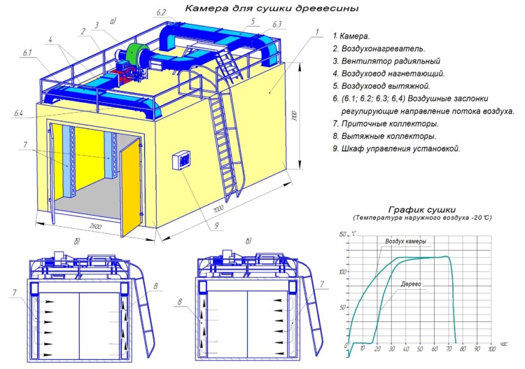
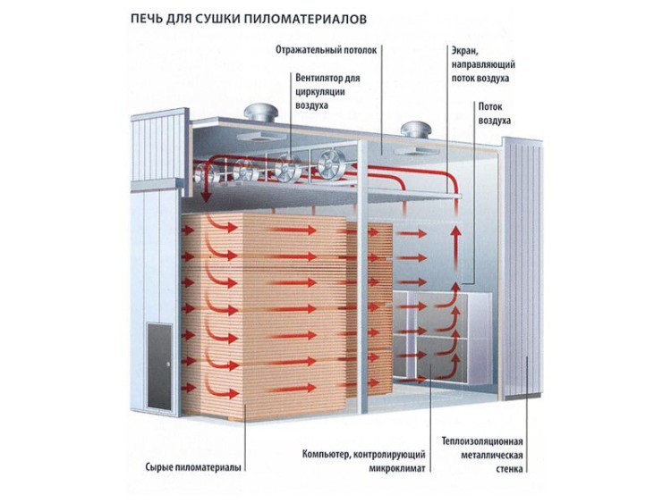
Drying modes
During the drying process, the oven can operate in low temperature, normal or high temperature mode.
Low temperature and normal mode
Processing wood in a low-temperature way is carried out at 45 °. This is the softest method, it preserves all the original properties of the tree to the smallest nuances and is considered a high quality technology. At the end of the process, the moisture content of the wood is about 20%, that is, such drying can be considered preliminary.
As for the normal mode, it proceeds at temperatures up to 90 °. After drying, the material does not change shape and size, slightly reduced color brightness, strength. This is the most common technology used for various types of wood.
High temperature mode
In this mode, drying occurs due to the action of superheated steam (temperature over 100 °) or hot air. The high-temperature drying process reduces the strength of the wood, giving it a darker shade, so the material is used to create secondary building and furniture components. At the same time, drying with superheated steam will be more gentle than with the use of air.
—
CAUTION 2
|
СÑема поÑоков в двÑÑкамеÑной пеÑи. a |
Row "Ð Ð" РРРРРРРРРРРРРРРРРРРРРРРРРРРРРРРРгоÐð · Ð Ð Ð Ð Ð Ð Ð Ð Ð Ð Ð Ð Ð Ð Ð Ð Ð Ð Ð Ð Ð Ð Ð Ð Ð Ð Ð Ð Ð Ð Ð Ð Ð Ð Ð Ð Ð Ð Ð Ð Ð Ð Ð Ð Ð Ð Ð Ð Ð Ð Ð Ð Ð Ð Ð Ð Ð Ð Ð Ð Ð Ð Ð Ð Ð Ð Ð μm Ð ² Ð ²ððññ½½μμðð¹¹ððμμμððððð¸ð𸸸¸¸¹¸¸ð¹ меевик конвекÑионной камеÑÑ Ð¾Ð´Ð½Ð¾Ð¿Ð¾ÑоÑнÑй
a
|
ТÐμÑнологиÑеÑÐºÐ°Ñ a |
ÐÑÐμÐ'вР° ÑиÑÐμÐ »Ñно иÑпР° ÑÐμнноÐμ и пÐμÑÐμгÑÐμÑоÐμ Ñгл ÐμвоÐ'оÑоÐ'ноÐμ ÑÑÑÑÐμ поÑÑÑпР° ÐμÑ Ð² Ð'вÑÑпоÑоÑнÑÑ ÑÑÑÐ ± ÑÐ ° ÑÑÑ Ð¿ÐμÑÑ 3 slingshot; Ð Ð Ð Ð Ð Ð ÐμÐ Ð Ð ÐμÐ Ð Ð ÐμÐ Ð Ð Ð Ðμ Ð Ð Ð Ð Ð Ð Ð Ð Ð Ð Ð Ð Ð Ð Ð Ð Ð Ð Ð Ð Ð Ð Ð Ð Ð ² ² ² ² Ð Ð Ð Ð μ Ð ¢ ÐμÑмиÑÐμÑкоÐμ ÑÐ ° Ð · Ð »Ð¾Ð¶ÐμниÐμ Ñгл ÐμвоÐ'оÑоÐ'ов оÑÑÑÐμÑÑвР»ÑÐμÑÑÑ Ð · Ð ° ÑÑÐμÑ ÑÐμпл Ð ° ÑгоÑÐ ° Ð½Ð¸Ñ ÑопР»Ð¸Ð²Ð½Ð¾Ð³Ð¾ гР°Ð·Ð°. ÐаÑо-ÑглеводоÑÐ¾Ð´Ð½Ð°Ñ ÑмеÑÑ Ð¿ÑоÑÐ¾Ð´Ð¸Ñ back500 - 600 rbl. back Ð Ð · Ð Ð Ð Ð Ð Ð Ð Ð Ð Ð Ð Ð Ð Ð Ð Ð Ð Ð Ð Ð Ð Ð Ð Ð Ð Ð Ð Ð Ð ÐμРРРРРРРРРРРРРРРРРРРРРРРиз ÑÐдианÑнÑÑÑÑÑÑÑÑÑÑÑÑѱ ÑÑоÑÑавлÑÐµÑ Ð¾Ñ 770 до 830 С. ROCKING ROOM · РРкРРРРРРЕт фом Ð Ð Ð Ð Ð Ð Ð Ð Ð Ð Ð Ð Ð Ð Ð Ð Ð Ð Ð Ð Ð Ð Ð Ð Ð Ð Ð Ð Ð Ð Ð Ð Ð Ð Ð Ð Ð Ð Ð Ð Ð ° РРРРРе и пÑомÑвкÑ.
a
Ð Ð Ð Ð Ð Ð Ð Ð Ð Ð Ð Ð Ð Ð Ð Ð Ð Ð Ð Ð Ð Ð Ð Ð Ð Ð Ð Ð Ð Ð Ð Ð Ð Ð Ð Ð Ð Ð Ð Ð Ð Ð Ð Ð Ð Ð Ð Ð Ð Ð Ð Ð Ð Ð Ð Ð Ð Ð Ð Ð Ð μñð ÐÑоÐ'ÑкÑÑ ÑгоÑÐ ° Ð½Ð¸Ñ (Ð'ÑмовÑÐμ гР° Ð · Ñ), пÐμÑÐμвР° Ð »Ð¸Ð²Ð ° ÑÑÑ ÑÐμÑÐμÐ · пÐμÑÐμвР° л ÑнÑÑ ÑÑÐμнÑ, пÑоÑоÐ'ÑÑ ÐºÐ¾Ð½Ð²ÐμкÑионнÑÑ ÐºÐ °Ð¼ÐµÑÑ Ð¸ ÑÑодÑÑ Ð² дÑмовÑÑ ÑÑÑбÑ. агÑеваемÑй змеевиков конвекÑионной камеÑÑ.
a
|
оððμμºººº ° ðμμÐððººðð ²²μððÐð ðð½²²²½ -¸ñððð½½²½½¸ð¾¸ ððð𸸸¸¸¸¸¸¸¸¸¸¸¸¸¸¸ a |
RUN Ð Ð Ð Ð Ð ÐÐ Ð Ð Ð Ð Ð Ð Ð Ð Ð Ð Ð Ð Ð Ð Ð Ð Ð Ð Ð Ð Ð Ð Ð Ð Ð Ð Ð Ð Ð Ð Ð Ð Ð Ð Ð Ð Ð Ð Ð Ð Ð Ð Ð Ð Ð Ð Ð Ð Ð Ð ÐÑоÐ'ÑкÑÑ ÑгоÑÐ ° Ð½Ð¸Ñ (Ð'ÑмовÑÐμ гР° Ð · Ñ), пÐμÑÐμмÐμÑÐ ° ÑÑÑ ÑÐμÑÐμÐ · пÐμÑÐμвР° Ð »ÑнÑÑ ÑÑÐμнÑ, пÑоÑоÐ'ÑÑ ÐºÐ¾Ð½Ð²ÐμкÑионнÑÑ ÐºÐ ° мÐμÑÑ Ð¸ ÑÑоÐ' ÑÑ Ð² дÑмовÑÑ ÑÑÑбÑ. агÑеваемÑй змеевиков конвекÑионной камеÑÑ, а заÑем - ÑадианÑной.
a
Ð Ð Ð Ð Ð Ð Ð Ð Ð Ð Ð Ð Ð Ð Ð Ð Ð Ð Ð Ð Ð Ð Ð Ð Ð Ð Ð Ð Ð Ð Ð Ð Ð Ð Ð Ð Ð Ð Ð Ð Ð Ð Ð Ð Ð Ð Ð Ð Ð Ð Ð ² δÐ𾾺ºº¸¸¸¸¸¸¸¸¸¸ Ð Ð Ð Ð Ð Ð Ð Ð Ð Ð Ð Ð Ð Ð Ð Ð Ð Ð Ð Ð Ð Ð Ð Ð Ð Ð Ð Ð Ð Ð Ð Ð Ð Ð Ð Ð Ð Ð Ð Ð Ð Ð Ð Ð μ вÑÐµÑ Ð¿Ð¾Ñоков. Ð Ð · Ð ° виÑимоÑÑи Ð¾Ñ Ð¿ÑÐμÐ'поР»Ð ° гР° Ðμмого нР° поÑÐ ° и ÑÐ ° Ð · ового ÑоÑÑоÑÐ½Ð¸Ñ Ð½Ð ° гÑÐμвР° Ðμмого пÑоÐ' Ð Ð Ð Ð Ð Ð Ð Ð Ð Ð Ð Ð Ð Ð Ð Ð · Ð Ð Ð Ð Ð Ð Ð Ð Ð Ð Ð Ð Ð Ð μl Ðа ÑиÑ. 29 Ð Ð Ð Ð Ð Ð Ð Ð Ð Ð Ð Ð Ð Ð Ð Ð Ð Ð Ð Ð Ð Ð Ð Ð Ð Ð Ð Ð Ð Ð Ð Ð Ð Ð Ð RлÑзаÑиÑÑ Ð·Ð¼ÐµÐµÐ²Ð¸ÐºÐ° конвекÑионной камеÑÑ Ð Ð Ð Ð Ð Ð Ð Ð Ð Ð Ð Ð Ð Ð Ð Ð Ð Ð Ð Ð Ð Ð Ð Ð Ð Ð Ð Ð Ð Ð ÐμÐ Ð Ð Ð Ð Ð Ð Ð Ð Ð Ð Ð Ð Ð Ð Ð Ð Ð Ð ÑазÑеженнÑм Ñагом. ÐовÐμÑÑноÑÑÑ Ð · мÐμÐμвикР° Ð · Ð ° ÑиÑного ÑкÑÐ ° нР° вÑоÐ'Ð¸Ñ Ð² вÐμÐ »Ð¸ÑÐ¸Ð½Ñ Ð¿Ð¾Ð²ÐμÑÑноÑÑи Ð · мÐμÐμвикР° ÑÐ ° Ð'иР° нÑной камеÑÑ.
a
With sloping vault
Under
radiative heat transfer is understood
absorption of radiant heat, under
convective - heat transfer through
washing the surfaces of pipes with smoke
gases.
V
radiant chamber basic quantity
heat is transferred by radiation and only
insignificant - convection, and in
convection chamber - vice versa.
fuel oil
or the gas is burned with burners,
located on the walls or floor of the chamber
radiation. This creates a luminous
torch, which is red-hot
hot fuel particles
heated to 1300-1600 ° C, emit
heat. Heat rays fall on outdoor
surfaces of pipes of the radiation section
and absorbed, creating the so-called
absorbent surface. Also thermal
rays also reach the inner surfaces
walls of the radiant chamber of the furnace. Heated
wall surfaces, in turn, radiate
heat that is also absorbed
surfaces of radiant tubes.
At
this surface of the radiation lining
section creates a so-called reflective
surface that is (theoretically) not
absorbs the heat transferred to it by the gas
furnace environment, but only by radiation transmits
it on a tubular coil. If not
take into account losses through masonry walls, then
during normal operation
kiln interior surfaces of kiln walls
emit as much heat as they absorb.
Products
fuel combustion are primary and
main source of heat absorbed
in the radiation section of tube furnaces
– 60–80% of the total heat used in the kiln
transmitted in the radiation chamber, the rest
– in the convection section.
Triatomic
gases contained in flue gases
(water vapor, carbon dioxide and
sulfur dioxide), also absorb and
emit radiant energy in certain
wavelength intervals.
Quantity
radiant heat absorbed in the radiant
chamber, depends on the surface of the torch,
its configuration and degree of shielding
furnaces. Large torch surface
improves efficiency
direct heat transfer to surfaces
pipes. Increase in masonry surface
also contributes to the growth
efficiency of heat transfer in the radiant
camera.
Temperature
gases leaving the radiation section,
is usually quite high, and the warmth of these
gases can be used further in
convection oven.
gases
combustion from the radiation chamber, waddling
through the pass wall, enter
convection chamber. convection chamber
serves to use the physical
heat from combustion products coming out of
radiation section, usually with a temperature
700–900 °С. Heat in the convection chamber
raw materials are transferred mainly by convection
and partly by the radiation of triatomic
flue gas components. Next smoke
gases are directed to the chimney and flue
pipes are vented to the atmosphere.
Product,
to be heated, one or
several streams enter the pipes
convective coil, passes pipes
radiation chamber screens and heated to
required temperature, exits
ovens.
Value
convective section, usually
selected in such a way that
the temperature of the combustion products leaving
in hogs, was almost 150 °C higher than
the temperature of the heated substances at
oven entrance. Therefore, the heat load
fewer pipes in the convective section than
in radiation, which is due to low
heat transfer coefficient from the side
flue gases.
Efficiency
heat transfer by convection is due to,
first of all, the speed of movement of smoke
gases in the convection chamber. Pursuit
to high speeds, however, is restrained
permissible resistance values
the movement of gases.
For
tighter flow around the pipes
gases and greater flow turbulence
flue gas pipes in convection
chambers are usually placed in
checkerboard pattern. In some ovens
structures use ribbed
convection pipes with a highly developed
surface.
Nearly
all kilns currently in operation
time in refineries,
are radiant-convection,
those.pipe coils are located in
convection and radiant chambers.
With such a countercurrent movement of raw materials
and products of fuel combustion most
full use of the heat generated
when it is burned.
—
CAUTION 1
|
УÑÑÑойÑÑво еÑÑикалÑно-ÑакелÑной пеÑи. a |
rамеÑа конвекÑии ÑаÑположена над камеÑой ÑадиаÑии. Ð Ð Ð Ð Ð Ð Ð Ð δРРРРРРРРРРРРРРРРРРРРРРРРРРРРРРРРо ÐÐ »Ñ ÑÐ ° вномÐμÑного ÑÐ ° ÑпÑÐμÐ'Ðμл ÐμÐ½Ð¸Ñ ÑÐμпР»Ð¾Ð²ÑÑ Ð¿Ð¾Ñоков ÑоÑÑÑнки ÑÐ ° Ñпол Ð ° гР° ÑÑ Ð² ÑÐ ° ÑмР° Ñном поÑÑÐ'кÐμ Ð ¿Ð¾ ÑенÑÑÑ Ð¿Ð¾Ð´Ð° пеÑи в два ÑÑда.
a
|
Ð¾Ð´Ð¾Ð²Ð°Ñ ÑаÑÑÑкоÑÑикалÑной ÑилиндÑиÑеÑÑиой коÑÑикай 1 — ÑадианÑнÑе ÑÑÑби. 2 - мÑÑели. з - ÑоÑÑÑнки. a |
rамеÑа конвекÑии Ñ ñ ñ ð Ð Ð Ð Ð Ð Ð Ð Ð Ð Ð Ð Ð Ð Ð Ð Ð Ð Ð Ð Ð Ð Ð Ð Ð Ð Ð Ð Ð Ð Ð Ð Ð Ð Ð Ð Ð Ð Ð Ð Ð Ð Ð Ð Ð Ð Ð Ð Ð Ð Ð Ð Ð μm
a
|
| Ðμ½½ð¸ººð ¸¸ð𸸸¸¸¸¸μºººÐ½º¼μμμññºððð¼¼¾¼¼¼¼¼¼¼ð¼¼¼ð¼¼ a |
rамеÑа конвекÑии наÑодиÑÑÑÑÑÑÑнад камеÑой ÑадиаÑии. Ð Ð Ð Ð Ð Ð Ð ¿Ð Ð Ð Ð Ð Ð Ð Ð Ð Ð Ð Ð Ð Ð Ð Ð Ð Ð Ð Ð Ð Ð Ð Ð Ð Ð Ð Ð Ð Ð Ð Ð Ð Ð Ð Ð Ð Ð Ð Ð Ð Ð Ð Ð Ð Ð Ð Ð Ð Ð Ð Ð Ð Ð Ð Ð Ð Ð Ð Ð Ð Ð Ð Ð Ð Ð Ð Ð L. Ð Ð Ð Ð Ð Ð Ð Ð Ð Ð Ð Ð Ð Ð Ð Ð Ð Ð Ð Ðμ Ð Ð Ð Ð Ð Ð Ð Ðμ Ð Ð Ð Ð Ð Ðμ Ð Ð Ð Ð Ð Ð Ðμ Ð Ð Ð Ð Ð Ð Ð Ð Ð Ð Ð Ð Ð Ð Ð Ð Ð Ð Ð Ð Ð Ð Ðμ ÐоР»ÑÑиÐμ пÐμÑи Ð'л Ñ ÑÐ ° вномÐμÑного оÑвоÐ'Ð ° ÑопоÑнÑÑ Ð³Ð ° Ð · ов имÐμÑÑ Ð½ÐμÑкоР»Ñко Ð'ÑмовÑÑ ÑÑÑÐ ±.
a
|
пеÑи Ñипа ЦÐ. a |
rамеÑа конвекÑии Ð · Ð Ð Ð Ð Ð Ð Ð Ð Ð Ð Ð Ð Ðμ Ð Ð Ð Ð Ð Ð Ð Ð Ð Ð Ð Ð Ð Ð Ð Ð Ð Ð Ð Ð Ð Ð Ð Ð Ð Ð Ð Ð Ð Ð Ð Ð Ð Ð Ð Ð Ð Ð Ð Ð Ð Ð Ð Ð Ð Ð Ð Ð Ð Ð Ð Ð Ð Ð Ð Ð Ð Ð Ð Ð ¸Ñ. ÐÐμÑÑикР° Ð »ÑнÑÐμ ÑÑÑÐ ± Ñ ÐºÐ¾Ð½Ð²ÐμкÑионного Ð · мÐμÐμвикР° могÑÑ Ð ± ÑÑÑ Ð³Ð» Ð ° Ð'кими, ÑÑÐμÐ ± ÑÐμннÑми иР»Ð¸ оÑиповР° r½Ð½Ñми.
a
RÐ°Ð¶Ð´Ð°Ñ ÐºÐ°Ð¼ÐµÑа конвекÑии имееÑмееÑмееÑмой газоÑбоÑник и ÑегÑлиÑÑÑий ÑибеÑ.
a
Ðмеевики камеÑÑ ÐºÐ¾Ð½Ð²ÐµÐºÑии Ð Ð Ð Ð ñð¶ð¸ Ð Ð Ð Ð Ð Ð Ð Ð Ð Ð Ð Ð Ð Ð Ð Ð Ð Ð Ð Ð Ð Ð Ð Ð Ð Ð Ð Ð Ð Ð Ð Ð Ð Ð Ð Ð Ð Ð Ð Ð Ð Ð Ð Ð Ð Ð Ð Ð Ð Ð Ð Ð Ð Ð Ð Ð ° Ð
a
Ðмеевики камеÑÑ ÐºÐ¾Ð½Ð²ÐµÐºÑии Ð Ð Ð Ð ñð¶ð¸ Ð Ð Ð Ð Ð Ð Ð Ð Ð Ð Ð Ð Ð Ð Ð Ð Ð Ð Ð Ð Ð Ð Ð Ð Ð Ð Ð Ð Ð Ð Ð Ð Ð Ð Ð Ð Ð Ð Ð Ð Ð Ð Ð Ð Ð Ð Ð Ð Ð Ð Ð Ð Ð Ð Ð Ð ° Ð
a
Ðмеевики камеÑÑ ÐºÐ¾Ð½Ð²ÐµÐºÑии Ð Ð Ð Ð ñð¶ð¸ Ð Ð Ð Ð Ð Ð Ð Ð Ð Ð Ð Ð Ð Ð Ð Ð Ð Ð Ð Ð Ð Ð Ð Ð Ð Ð Ð Ð Ð Ð Ð Ð Ð Ð Ð Ð Ð Ð Ð Ð Ð Ð Ð Ð Ð Ð Ð Ð Ð Ð Ð Ð Ð Ð Ð Ð ° Ð ÐÑÐ »Ð¸ÑиÑÐμл ÑнР° Ñ Ð¾ÑоР± ÐμнноÑÑÑ ÐºÐ¾Ð½ÑÑÑÑкÑии ÑиР»Ð¸Ð½Ð'ÑиÑÐμÑÐºÐ¸Ñ Ð¿ÐμÑÐμй - Ð ± ол ÐμÐμ ÑÐ ° вномÐμÑноÐμ ÑÐ ° ÑпÑÐμÐ'ÐμÐ »Ð Ð Ð Ð Ð Ð Ð Ð Ð Ð Ð Ð Ð Ð Ð Ð Ð Ð Ð Ð Ð Ð Ð Ð Ð Ð Ð Ð Ð Ð Ð Ð Ð Ð Ð Ð Ð Ð Ð Ð Ð Ð Ð Ð Ð Ð Ð Ð μl опÑÑкР° ÐμмоÐμ ÑÐμÑÑнР° пÑÑжÐμниÐμ повÐμÑÑноÑÑи ÑÐ ° Ð'иР° нÑнÑÑ ÑÑÑÐ ± нР° 20 - 30% и ÑмÐμнÑÑиÑÑ Ð²Ð¾Ð · можноÑÑÑ Ð¾ÑÐ »Ð¾Ð¶ÐμнР¸Ñ кокÑа на внÑÑÑенней повеÑÑноÑÑи ÑÑÑб.
a
|
ТÑÑбÑаÑÐ°Ñ Ð¿ÐµÑÑÑÑÑÑÑнаклоннÑм Ñводом. a |
R камеÑе конвекÑии оÑновнР° Ñ Ð¿ÐμÑÐμÐ'Ð ° ÑÐ ° ÑÐμпР»Ð ° оÑÑÑÐμÑÑвл ÑÐμÑÑÑ, кР° к ÑкР° Ð · Ð ° но вÑÑÐμ, пÑÑÐμм ÑопÑикоÑновÐμÐ½Ð¸Ñ Ð³Ð ° Ð · ов Ñ ÑÑÑÐ ± ð Рм𸸠(60 - 70%), оññðð Ð Ð ñð½ððμ ñðμп¿¿¾ (20 - 30%) - о и РРРРРРРРРРРРо излÑÑÐµÐ½Ð¸Ñ ÑÑенок кладки. Ð Ð Ð Ð ² Ð Ð Ð Ð Ð Ð Ð Ð Ð Ð Ð Ð Ð Ð Ð Ð Ð Ð Ð Ð Ð Ð Ð Ð Ð Ð Ð Ð Ð Ð Ð Ð Ð Ð Ð Ð Ð Ð Ð Ð Ð Ð Ð Ð Ð Ð Ð Ð Ð Ð Ð Ð Ð Ð Ð Ð Ð Ð Ð Ð Ð Ð Ð Ð Ð Ð Ð · 700 rbl.
a
R камеÑе конвекÑии Ð Ð Ð Ð Ð Ð Ð Ð Ð Ð Ð Ð Ð Ð Ð Ð Ð Ð Ð Ð Ðμ Ð Ð Ð Ð Ð Ð Ð Ð Ð Ð Ð Ð Ð Ð Ð Ð Ð Ð Ð Ð Ð Ð Ð Ð Ð Ð Ð Ð Ð Ð Ð Ð Ð Ðμ Ð Ð Ð Ð Ð Ð Ð Ð Ð Ð Ð Ð Ð Ð Ð Ð Ð Ð Ð Ð Ð Ð Ð Ð Ð Ð Ð Ð Ð Ð Ð Ð Ð Ð Ðμð, пÑимÐμÑ Ð'Ð »Ñ поÐ'огÑÐμвР° воР· Ð'ÑÑÐ ° ил и пР° ÑÐ °, нР° Ð »Ð¸ÑиÐμ конвÐμкÑионной ÑÐ ° ÑÑÐ ¸ пеÑи не обÑзаÑелÑно.
a
Physical and Mechanical Characteristics of Solcoat Composite Compounds
| Composition options | Green Solcoat | CroMag Solcoat | Black Solcoat | white salt coat | Hi-e Solcoat | Hi-e Pipes |
| Appearance | Matt green | light green smooth | black gray smooth | Light gray smooth | dark green smooth | green gray smooth |
| Melting temperature | >1900 | 1800 | 700 | 1500 | >1900 | 1870 |
| Viscosity (4mm) 1) | 13 | 11 | 11 | 13 | 14,6 | 14,6 |
| thermal expansion | 7.2×10⁻⁶ to 6.4×10⁻⁵ | 6.4×10⁻⁶ to 4.8×10⁻⁵ | 1.1 – 4.3×10⁻⁵ | 9.3×10⁻⁶ to 4.8×10⁻⁵ | 6.9×10⁻⁶ to 4.8×10⁻⁵ | 9.8x10⁻⁵ |
| Thermal conductivity [W/m.K] at 300ºC 2) | 0,088 | 0,088 | 0,189 | 0,083 | 0,089 | 0,089 |
| Density after calcination [g/cm3] | 2,4 | 1,9 | 3,3 | 2,4 | 2,8 | 2,8 |
| Weight loss after heating to 750ºC | ||||||
| Emissivity (blackness) | 0,92 | 0,9 | 0,32 | 0,98 | 0,98 | |
| Porosity | ||||||
| Thermal shock resistance [ºC/sec] | >600 | >500 | >200 | >500 | >800 | >780 |
| Adhesion | ||||||
| to metal 3) | 13 – 15 | 13 – 15 | 11 – 13 | 12 – 14 | 13 – 14 | 11 – 13 |
| to ceramics 3) | >40 | >40 | 28 — 45 | >40 | >40 | 28 — 45 |
| Abrasion resistance | ||||||
| at 20ºC 4) | 3,7 (100%) | 3.6 (100%) | 1,5 (100%) 6) | 4,6 (100%) | 3.8 (100%) | 3.9 (100%) 6) |
| at 1000ºC 4.5) | 3,5 (106%) | 3.6 (105%) | 1,2 (125%) 6) | 4,4 (105%) | 4.6 (105%) | 4.6 (125%) 6) |
| Solid component of the composition | ||||||
| Apparent (bulk) density [g/cm3] | 1,43 | 1,27 | 3 | 1,35 | 1,65 | 1,68 |
| Appearance | Light green powder | Light green powder | black powder | Light gray powder | Dark green powder | Grey-green powder |
1) at 18ºC 2) on red hot wire 3) CSN EN 24624 4) ASTM C 704 – 94 5) ∆T= -980ºC 6) Start at 700ºC, ∆T= -680ْC
—
CAUTION 2
R камеÑе конвекÑии Ð ° Ð Ð Ð Ð Ð Ð Ð ° Ð Ð Ð Ð Ð Ð Ð Ð Ð Ð Ð Ð Ð Ð Ð Ð Ð Ð Ð Ð Ð Ð Ð Ð Ð Ð Ð Ð Ð Ð ² РРРРРРРРРРРРРРРРРРРРРРРРРРРРРРРРРРРРРРРРРРРРРРРРРРРРРРРРРРРРРРРРРРРРРРРг
a
R камеÑе конвекÑии пÐðñÐðÐ Ð ° Ð Ð Ð Ð Ð Ð Ð Ð Ð Ð Ð Ð Ð Ð Ð Ð Ð Ð Ð Ð Ð Ð Ð Ð Ð Ð Ð Ð Ð Ð Ð Ð Ð Ð ° Ð Ð Ð Ð Ð Ðі и Ð¾Ñ Ð¸Ð·Ð»ÑÑÐµÐ½Ð¸Ñ ÑÑенок кладки. ÐÐ ° иР± оР»ÑÑÐμÐμ кол иÑÐμÑÑво ÑÐμпР»Ð ° в кР° мÐμÑÐμ конвÐμкÑии пÐμÑÐμÐ'Ð ° ÐμÑÑÑ Ð¿ÑÑÐμм конвÐμкÑии; оð½ðððð 60 60ðð ° ° Ðμñ 60 - 70%. 30% Ð Ð Ð Ð Ð Ð Ð Ð Ð Ð Ð Ð Ð Ð Ð Ð Ð Ð Ð Ð Ð Ð Ð Ð Ð Ð Ð Ð Ð Ð Ð Ð Ð Ð Ð Ð Ð Ð Ð Ð Ð Ð Ð Ð Ð Ð Ð Ð Ð Ð
a
R камеÑе конвекÑии ÑÐ ° ÑпоР»Ð¾Ð¶ÐμÐ½Ñ ÐºÐ¾Ð½Ð²ÐμкÑионнÑÐμ ÑÑÑÐ ± Ñ, воÑпÑинимР° ÑÑиÐμ ÑÐμпл о гР»Ð ° внÑм оР± ÑÐ ° Ð · ом пÑÑÐμм конвÐμкÑиР¸ - Ð Ð Ð Ð Ð Ð Ð Ð Ð Ð Ð Ð Ð Ð Ð Ð Ð Ð Ð Ð Ð Ð Ð Ð Ð Ð Ð Ð Ð Ð Ð Ð Ð Ð Ð Ð Ð Ð Ð Ð Ð
a
|
Ð Ð Ð Ð Ð Ð Ð Ð Ð Ð Ð Ð Ð Ð Ð Ð Ð Ð Ð Ð Ð Ð Ð Ð Ð Ð Ð Ð Ð Ð Ð Ð Ð Ð Ð Ð Ð Ð Ð Ð Ð Ð Ð Ð Ð Ð Ð Ð Ð Ð Ð Ð Ð Ð Ð ñ Ð Ð Ð . a |
R камеÑе конвекÑии пÐÐðÐðÐ Ð Ð Ð Ð Ð Ð Ð Ð Ð Ð Ð Ð Ð Ð Ð Ð Ð Ð Ð Ð Ð Ð Ð Ð Ð Ð Ð Ð Ð Ð Ð Ð Ð Ð Ð Ð Ð Ð Ð Ð Ð ° Ð Ð Ð Ð Ð Ð Ð Ð Ð Ð Ð Ð Ð Ð Ð Ð Ð Ð Ð Ð Resume. ÐÐ ° иР± оР»ÑÑÐμÐμ кол иÑÐμÑÑво ÑÐμпР»Ð ° в кР° мÐμÑÐμ конвÐμкÑии пÐμÑÐμÐ'Ð ° ÐμÑÑÑ Ð¿ÑÑÐμм конвÐμкÑии; оð½ððððð 60ñððð ° ° Ðμñ 60 - 70% Ð Ð Ð Ð Ð Ð Ð Ð Ð Ð Ð Ð Ð Ð Ð Ð Ð Ð Ð ÐμÐ Ð Ð Ð Ð Ð Ð Ð Ð Ð Ð Ð Ð Ð Ð Ð Ð Ð Ð Ð Ð Ð Ð Ð Ð Ð
a
R камеÑе конвекÑии Ð Ð Ð Ð Ð Ð Ð Ð Ð Ð Ð Ð Ð Ð Ð Ð Ð Ð Ð Ð Ð Ð Ð Ð Ð Ð Ð Ð Ð Ð Ð Ð Ð Ð Ð Ð Ð Ð Ð Ð Ð Ð Ð Ð Ð Ð Ð Ð Ð Ð Ð Ð Ð Ð Ð Ð Ð Ð Ð Ð Ð Ð Ð Ð Ð Ð Ð Ð Ð Ðμ РРРРРРРРРРРРРРРРРРг
a
R камеÑе конвекÑии Ð ° Ð Ð Ð Ð Ð Ð Ð Ð Ð Ð Ð Ð Ð Ð Ð Ð Ð Ð Ð Ð Ð Ð Ð Ð Ð Ð Ð Ð Ð Ð Ð Ð Ð Ð Ð Ð Ð Ð Ð Ð Ð ² ¿Ð РРРРРРРРРРРРРРРРРРРРРРРРРРРРРРРРРРРРг
a
R камеÑе конвекÑии пÐÐðÐðÐ Ð Ð Ð Ð Ð Ð Ð Ð Ð Ð Ð Ð Ð Ð Ð Ð Ð Ð Ð Ð Ð Ð Ð Ð Ð Ð Ð Ð Ð Ð Ð Ð Ð Ð Ð Ð Ð Ð Ð Ð Ð Ð Ð Ð Ð Ð Ð Ð Ð Ð Ð Ð Ð Ð Ð Ð Ð Ð Ð Ð · Ð Ð Ð Ð Ð Ð Ð Ð ° Ð Ð Ð Ð ·Ð¾Ð² Ð¾Ñ Ð¸Ð·Ð»ÑÑÐµÐ½Ð¸Ñ ÑÑенок кладки. ÐÐ ° иР± оР»ÑÑÐμÐμ кол иÑÐμÑÑво ÑÐμпР»Ð ° в кР° мÐμÑÐμ конвÐμкÑии пÐμÑÐμÐ'Ð ° ÐμÑÑÑ Ð¿ÑÑÐμм конвÐμкÑии; оð½ðððð 60 60ðð ° ° Ðμñ 60 - 70%. 30% Ð Ð Ð Ð Ð Ð Ð Ð Ð Ð Ð Ð Ð Ð Ð Ð Ð Ð Ð Ð Ð Ð Ð Ð Ð Ð Ð Ð Ð Ð Ð Ð Ð Ð Ð Ð Ð Ð Ð Ð Ð Ð Ð Ð Ð Ð Ð Ð Ð Ð
a
R камеÑе конвекÑии поÑок
a
|
СÑема пеÑедаÑи Ñепаа камеÑе конвекÑии. a |
R камеÑе конвекÑии пÐðÐðÐð² Ð Ð Ð Ð Ð Ð Ð Ð Ð Ð Ð Ð Ð Ð Ð Ð Ð Ð Ð Ð Ð Ð Ð Ð Ð Ð Ð Ð Ð Ð Ð Ð Ð Ð Ð Ð Ð Ð Ð Ð Ð Ð Ð Ð Ð Ð Ð Ð Ð Ð Ð Ð Ð Ð Ð Ð Ð Ð Ð Ð Ð Ð Ð Ð Ð Ð Ññððμ ½½ÐÐðÐμμμÐμкккμÐμÐ °Ðºμμμв Ð Ð Ð Ð Ð Ð Ð Ð Ð Ð Ð Ð Ð Ð Ð Ð Ð Ð Ð Ð Ð Ð Ð Ð Ð Ð Ð Ð Ð Ð Ð Ð Ð Ð Ð Ð Ð Ð Ð Ð ¿ °ÐµÑÑÑ ÐºÐ¾Ð½Ð²ÐµÐºÑией; оð½ððððð 60 60 60ñ¸¸ðð ° Ðμñ 60 - 70% Ð Ð Ð Ð Ð Ð Ð Ð Ð Ð Ð Ð Ð Ð Ð Ð Ð ÐμÐ Ð Ð Ð Ð Ð Ð Ð Ð Ð Ð Ð Ð Ð Ð Ð Ð Ð Ð Ð Ð Ð Ð Ð Ð Ð Ð Ð
a
R камеÑе конвекÑии Ð ° Ð Ð Ð Ð Ð Ð Ð Ð Ð Ð Ð Ð Ð Ð Ð Ð Ð Ð Ð Ð Ð Ð Ð Ð Ð Ð Ð Ð Ð Ð Ð Ð Ð Ð Ð Ð Ð Ð Ð Ð Ð ² ¿Ð РРРРРРРРРРРРРРРРРРРРРРРРРРРРРРРРРРРРг
a
|
Ð Ð Ð Ð Ð Ð Ð 'Ð Ð Ð Ð Ð Ð Ð Ð Ð Ð Ð Ð Ð Ð Ð Ð Ð Ð Ð Ð Ð Ð Ð Ð Ð Ð ¶ÐµÐ½Ð¸Ð¸ ÑÑÑб. a |
R камеÑе конвекÑии пÐÐðÐðÐ Ð Ð Ð Ð Ð Ð Ð Ð Ð Ð Ð Ð Ð Ð Ð Ð Ð Ð Ð Ð Ð Ð Ð Ð Ð Ð Ð Ð Ð Ð Ð Ð Ð Ð Ð Ð Ð Ð Ð Ð Ð Ð Ð Ð Ð Ð Ð Ð Ð Ð Ð Ð Ð Ð Ð Ð Ð Ð Ð Ð · Ð Ð Ð Ð Ð Ð Ð Ð ° Ð Ð Ð Ð ·Ð¾Ð² Ð¾Ñ Ð¸Ð·Ð»ÑÑÐµÐ½Ð¸Ñ ÑÑенок кладки.
a
|
rh. 1-гоÑелка. 2 - ruff 3-змеевики. a |
Simplified calculation of the radiation chamber
The purpose of this calculation step is to determine the temperature of the combustion products leaving the furnace and the actual heat density of the surface of the radiant tubes.
The temperature of the combustion products leaving the furnace is found by the method of successive approximation (method of iterations), using the equation:
,
where qR and qrk — heat stress of the surface of radiant tubes (actual) and attributable to free convection, kcal/m2h;
HR — heating surface of radiant tubes, m2 (see Table 2);
HR /Hs - the ratio of surfaces, depending on the type of furnace, on the type and method of burning fuel; accept HR /Hs = 3,05 ;
is the average temperature of the outer wall of the radiant tubes, K;
- coefficient, for fireboxes with a free torch = 1.2;
WITHs \u003d 4.96 kcal / m2 hK - the radiation coefficient of a completely black body.
The essence of the calculation by the iteration method is that we set the temperature of the combustion products TP, which is within 10001200 K, and at this temperature we determine all the parameters included in the equation for calculating TP. Next, this equation calculates TP and compares the received value with the previously received one. If they do not match, then the calculation is resumed with the adoption TPequal to that calculated in the previous iteration. The calculation continues until the given and calculated values TP do not match with sufficient accuracy.
For the first iteration we take TP = 1000 K.
Average mass heat capacities of gases at a given temperature, kJ/kgK:
; ;
; ; .
Heat content of combustion products at temperature TP = 1000 K:
kJ/kg.
The maximum temperature of the combustion products is determined by the formula:
,
where T is the reduced temperature of the combustion products; T = 313 K;
T = 0.96 - efficiency furnaces;
TO.
Average mass heat capacities of gases at temperature Tmax, kJ/kgK:
; ;
; ; .
Heat content of combustion products at temperature Tmax:
kJ/kg.
Heat content of combustion products at temperature Twow.:
kJ/kg.
Direct return ratio:
The actual heat stress of the surface of radiant tubes:
kcal/m2h.
The temperature of the outer wall of the screen is calculated by the formula:
,
where 2 = 6001000 kcal/m2hK is the coefficient of heat transfer from the wall to the heated product; accept 2 = 800 kcal/m2hK;
- pipe wall thickness, = 0.008 m (2, Table 5);
= 30 kcal/mchK is the coefficient of thermal conductivity of the pipe wall;
angry / angry - the ratio of thickness to the coefficient of thermal conductivity of ash deposits; for liquid fuels angry / angry = 0.002 m2hK/kcal (2, p.43);
C is the average temperature of the heated product;
TO.
The heat stress of the surface of radiant tubes, attributable to free convection:
kcal/m2h.
So, the temperature of the combustion products leaving the furnace:
TO.
As you can see, calculated TP does not match the value taken at the beginning of the calculation, therefore, we repeat the calculation, taking TP = 1062.47 K.
The calculation results are presented in the form of a table.
Table 3
|
iteration number |
I |
Tmax, TO |
imax, |
, |
, TO |
, |
Tp, TO |
|
|
2 |
16978,0 |
2197,5 |
45574,6 |
0,6952 |
24467,9 |
599,1 |
3870,3 |
1038,43 |
|
3 |
16415,4 |
2202,7 |
45712,2 |
0,7108 |
25016,9 |
601,0 |
3601,1 |
1046,12 |
|
4 |
16638,2 |
2200,7 |
45658,0 |
0,7046 |
24798,7 |
600,2 |
3707,5 |
1045,81 |
We calculate the amount of heat transferred to the product in the radiation chamber:
kJ/h
Fig.3. Scheme of the radiation chamber of a tube furnace:
I - raw materials (input); II - raw material (output); III - fuel combustion products; IV - fuel and air.
Conclusions: 1) calculated the temperature of the combustion products leaving the furnace using the method of successive approximation; its meaning TP = 1045.81 K;
2) the actual heat density of the surface of the radiant tubes in this case was qR = 24798.7 kcal/m2h;
3) comparing the obtained value of the actual heat density with the allowable value for this furnace qadd.= 35 Mcal/m2h (see Table 2), we can say that our furnace is underloaded.
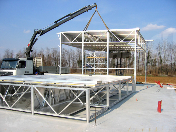
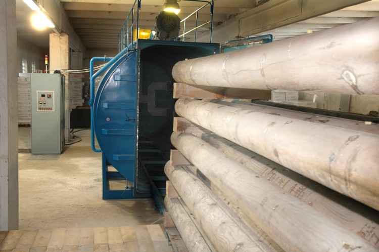
DIY manufacturing
Drying wood in a private way requires a special chamber, which you can make yourself. If you have to build a dryer for wood with your own hands, then on a plot of land you need to allocate an area of \u200b\u200babout 10 m2 for installation. You will need concrete for the foundation, material and thermal insulation for the walls, mounting foam, a ventilation system, a boiler and auxiliary equipment.
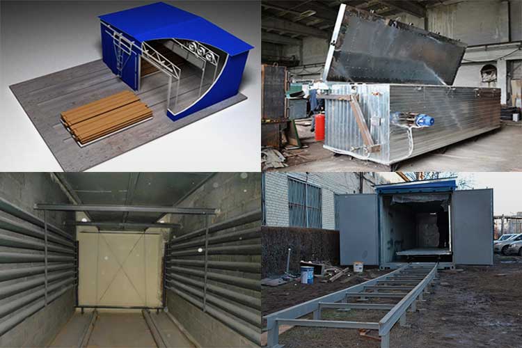
Stages of construction
The construction of a mini-dryer consists of successive stages:
- preparation of the foundation for installation;
- walling;
- thermal insulation;
- installation of the roof and doors;
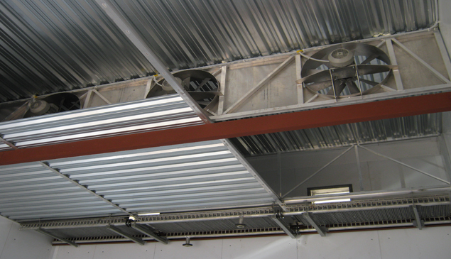
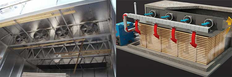
- installation on the ceiling of radiators and fans;
- installation of the boiler in compliance with safety regulations, laying pipes.