Basement gas inlet to the house
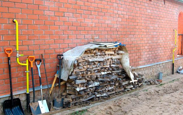
If you have a country house and have decided to gasify it, then you will need a basement gas pipeline. Its main task is to provide the shortest path from the main pipeline directly to the gas boiler.
If all communications to the house are a gas pipeline, sewerage, water supply pass underground, they, as a rule, try to place them on one side of the house. In this case, according to the norms of SNiP, it is necessary to maintain a distance between them.
Definition of gas input and its application
Let's define the concept of a basement gas inlet and its purpose. This device, which is a single connection of two pipes, which allows you to provide a reliable transition from the polyethylene pipe of the gas pipeline to the steel pipe of the house. It is protected from external damage by a steel shell, which is closed with plugs.
Installation of a socle gas inlet
It is possible to make the base entry yourself, but in this case you will need to carry out radiographic control and translucence of welds. To avoid unnecessary procedures, it is easier to use ready-made gas inlets to supply it to any floor of the house. They are manufactured at the enterprise in strict accordance with SNiP 42-103-2003 and in various sizes.
If the house is located in an area with a cold climate or high seismicity, then you can choose a basement entry that is suitable for working in the required conditions. This will help to avoid problems associated with the work on connecting gas systems. They have a margin of safety twice as high as the pressure in the gas pipeline, which will ensure safety when using the base entry.
Types of socle gas inlets
L-shaped base gas inlet
Gas inlets for the house are divided into three types.
- L-shaped basement gas inlet. It is intended for a bunch of a pipe from steel and polyethylene. Its design consists of a metal pipe protected from water ingress and having an integral transition, which is called "Steel-polyethylene". The polyethylene gas pipe is resistant to low temperatures, and therefore the L-shaped bushing can be used in areas with winter temperatures that fall below -20 degrees.
- Direct ground entry. It is mounted at the exit of the gas pipe from the surface of the earth and up to the pipe of a residential building. Its body is entirely made of special polyethylene. A feature of this type of device is the so-called "free bend", mounted in a flexible case. The bend itself is located at the bottom of the input itself, and the one-piece connection is located at the top and has a steel protective shell. It can be used only in those areas where the winter temperature is not more than 15 degrees.
- I-shaped input. It has the appearance of a straight steel or polyethylene pipe with a corrugated metal tube (bellows) and a faucet. It is attached by welding. It is located at the exit of the gas pipe from the ground near the house. The one-piece transition is located in the vertical section of the device. The I-shaped base entry is provided with thermal insulation and is well protected from external damage. This function is performed by the case. The use of such an input is permissible in different climatic zones. It has a high margin of safety.
Benefits when using
When carrying out gasification of the house, it is necessary to use a basement input. Watch the video on how the house is connected to the outdoor gas pipeline system.
Ground entry has a number of advantages:
- Cost savings due to the small need for facade repairs.
- Savings on the performance of radiographic inspection and welding seams.
- Due to good insulation, the basement is protected from water ingress and temperature changes. All this together allows you to significantly increase the service life.
- The system, equipped with a plinth entry, can be used in regions with low temperatures. This is achieved by using well-insulated cases.
- A large margin of safety allows them to be used in earthquake-prone areas.
- It is permissible to use a socle input in soils with heaving properties.
To avoid undesirable consequences caused by the explosiveness of the gas, its installation must be entrusted to experienced specialists.
Analysis of the main parameters of the gas supply system
Domestic gas pipeline network
The gas supply system has a dead-end scheme.
The laying of external gas pipelines is accepted underground. The low pressure gas pipeline is laid in a trench. The bottom of the trenches is leveled with a layer of coarse-grained sand 10 cm thick, and after laying the gas pipeline is covered with sand to a height of at least 20 cm.
To determine the location of the gas pipeline using the instrumental method, an insulated satellite wire is placed directly on the gas pipeline.
The gas pipeline is laid with a slope of at least 0.002% to remove moisture released from the gas. Condensation pots are installed in the lower parts of gas pipelines, in which the released moisture accumulates.
At the exit from the ground of the gas pipeline, a PEF63/StF57 base inlet is provided, with a permanent PE/ST connection. Gas is supplied to the residential building from the yard facade.
Installation of disconnecting devices is provided on the wall of the building at the outlet of the gas pipeline from the ground at a height of 1.8 m from the ground. Steel ball valves with insulating joint are accepted for installation.
The above-ground steel gas pipeline was coated with a paintwork consisting of 1 layer of primer "Universum" Finish A10 and 2 layers of methyl methacrylate enamel "Universum" Finish A12..
The projected low-pressure gas pipeline is made from the tie-in point into the existing low-pressure gas pipeline. The pressure at the tie-in point is 1.8 kPa.
The pipes are connected by welding. Types, structural elements and dimensions of welded joints of steel gas pipelines comply with GOST.
Intra-house gas pipeline
Installation of internal gas equipment is carried out after the following work:
- installation of interfloor ceilings, walls and partitions, on which gas pipelines, fittings, gas equipment and appliances will be mounted;
- arrangement of holes, channels and furrows for laying gas pipelines in foundations, walls, partitions and ceilings;
- plastering of walls in kitchens and other rooms in which the installation of gas equipment is provided;
Internal gas pipelines are mounted from steel pipes. Pipe connections are provided for welding. Gas pipelines are laid openly.
The gas pipeline - the collector is laid along the outer wall of a residential building between the windows of the 1st and 2nd floors at a distance of 3.25 m from the ground. The diameter of the gas collector running along the outer wall of the building is assumed to be constant and equal to 57 mm in accordance with the hydraulic calculation. Risers are accepted with a diameter of Dy = 25 mm and are placed along the outer wall. They are laid vertically. Permissible deviation is not more than 2 mm per meter of gas pipeline length.
It is forbidden to lay risers in residential premises, bathrooms and sanitary facilities.
Disconnect devices are installed on risers and in front of gas appliances.
In total there are 4 risers in the building.
Enclose the gas pipeline passing through the wall and ceiling in a case. The diameter of the case is assumed to be 57 mm. The space between the ceiling and the case is filled with mortar for the entire thickness of the structure. The ends of the case are sealed with elastic material. In the case, the gas pipeline is painted with oil paint in two layers. The case itself is stuffed with resin tow and filled with bitumen. The edges of the case protrude 3 cm above the floor and do not come out of the ceiling.
The apartment wiring of the gas pipeline is carried out along the walls at a distance of 55 cm from the ceiling and 5 cm from the wall for ease of operation.
To account for gas consumption in kitchens, Grand-4 gas meters are installed at a distance of 1 m from the gas stove, mounted vertically at a height of 1.7 m from the floor level.
The disconnecting devices are mounted in front of the gas meter at a height of 1.95 m from the floor level. The gas stove is attached to the gas pipeline on a rigid connection (pipe).
In the kitchen, the gas stove is installed permanently, on a flat surface. A 4-burner stove has been adopted.
For the removal of combustion products, prefabricated chimneys are provided, which are removed above the roof of the building and end with a deflector. To ventilate the room, there is a window with a glazing area of 1.53 m2.
Gas base inlets
 Joomla 2.5 themescalendars and events for Joomla
Description and application of gas base inlets
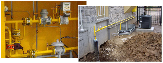
Gas socle inlets are installed at the points of transition of the external underground gas pipeline to the above-ground position, as well as where the exit is located in close proximity to the building.
The gas base inlet can be made by bending a plastic pipe with a polyethylene-steel connection in a protective case (Fig. b).
As well as gas base inlets are made using a branch and embedded heaters (Fig. c)
Gas socle inputs are covered with a reinforced insulating coating in accordance with GOST 9.602-2005 and RD 153-39.4-091-01.
Varieties of gas base inlets
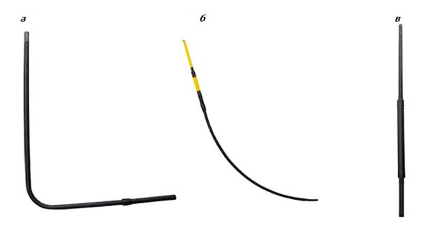
According to the Code of Rules for the design and construction of gas pipelines from polyethylene pipes SP 42-103-2003 ″, it is possible to use three types of gas base inlets:
a - steel gas base inlet;
b - polyethylene gas base inlet, with a free bend of the pipe;
c - polyethylene gas base inlet, using an outlet with embedded heaters.
1 - steel section of the basement input; 2 - transition "steel-polyethylene"; 3 - polyethylene gas pipeline; 4 - case; 5 - curved polyethylene case; 6 - outlet with embedded heaters; 7 - electrical insulating device
LLC "NIZHPOLYMER" offers all types of gas base inlets, in accordance with the set of rules SP 42-103-2003.
a - L-shaped (bent) gas base inlet from a steel insulated pipe.
Such a gas base inlet is a very reliable and time-tested product that can be used in the cold season at low temperatures, due to the fact that the permanent connection is underground. Such a gas base inlet has a diameter of 32x34 (Dn25) and 63x57 (90x89, 110x108) and is manufactured without a welded joint.
Gas socle inlets with a diameter of 160x159, 225x219, 315x273 and above are manufactured with a welded joint with a protocol for their verification. The steel part is insulated with a four-layer tape "Polylen" based on thermolight-stabilized polyethylene and butyl rubber. The insulation layer is more than 1.8 mm.
b - Direct gas base inlet with a free bend of a polyethylene pipe.
The diameter of direct gas socle inlets is 32x34(Dn25)mm.
c - Gas base inlet of a gas pipeline with a straight section of a polyethylene pipe and an insulated steel pipe (i-shaped base inlet).
Such a gas base inlet is used in various climatic zones, due to the underground location of 0.5 m. The upper part of such an input is also reinforced with a four-layer Polylen tape based on thermo-light-stabilized polyethylene and butyl rubber. The insulation layer is more than 1.8 mm.
Table of gas base inlets at NizhPolymer:
| Name | Weight, kg | Pipe PE GOST 50838-95 | Steel pipe | L1, not less than mm | L2, not less than mm | L3 no more than mm | dmm | d1mm |
| VCG PE 80 GAS SDR 11 32/st25 GOST 3262-75 (2х1)** | 6,96 | 32x3.0 | 25x3.2 | 1800 | 1100 | 300 | 32 | 32 |
| VCG PE 80 GAS SDR 11 32/st32 GOST 8732-78 (2х1) | 6,47 | 32x3.0 | 32x3.0 | 1800 | 1100 | 300 | 32 | 32 |
| VCG PE 80 GAS SDR 11 32/st25 GOST 3262-75 (2х2)*** | 9,87 | 32x3.0 | 25x3.2 | 1800 | 2100 | 300 | 32 | 32 |
| VCG PE 80 GAS SDR 11 32/st32 GOST 8732-78 (2x2) | 9,17 | 32x3.0 | 32x3.0 | 1800 | 2100 | 300 | 32 | 32 |
| VCG PE 80 GAS SDR 11 40/st32 GOST 3262-75 (2х1) | 9,00 | 40x3.7 | 32x3.2 | 1800 | 1100 | 300 | 40 | 38 |
| VCG PE 80 GAS SDR 11 40/st38 GOST 8732-78 (2х1) | 7,73 | 40x3.7 | 38x3.0 | 1800 | 1100 | 300 | 40 | 38 |
| VCG PE 80 GAS SDR 11 40/st32 GOST 3262-75 (2x2) | 12,74 | 40x3.7 | 32x3.2 | 1800 | 2100 | 300 | 40 | 38 |
| VCG PE 80 GAS SDR 11 40/st38 GOST 8732-78 (2x2) | 10,92 | 40x3.7 | 38x3.0 | 1800 | 2100 | 300 | 40 | 38 |
| VCG PE 80 GAS SDR 11 63/st57 GOST 10705-80 (2x1) | 13,24 | 63x5.8 | 57x3.5 | 1800 | 1100 | 300 | 63 | 38 |
| VCG PE 80 GAS SDR 11 63/st57 GOST 10705-80 (2x2) | 18,82 | 63x5.8 | 57x3.5 | 1800 | 2100 | 300 | 63 | 38 |
| VCG st57 GOST 10705-80 (2x3) | 25,38 | – | 57x3.5 | 1800 | 3000 | 300 | 57 | 38 |
Additional complete set of gas socle inputs
, if necessary, is ready to supply gas base gas pipeline inlets in the following configurations:
1) Mounted gas valves;
2) Bellows expansion joints insulating joints;
3) Electrofusion bends.
And also various standard sizes are possible (2x1, 2.5x1.3, 2x1.5, 2x2, etc.)
Commissioning of intra-house gas pipelines
Responsibility for the condition and proper operation of in-house gas equipment and gas pipelines in cities and towns is borne by the operating organizations of the gas economy. Departmental and private houses are serviced by the relevant house administrations (ZHEK), gas operating organizations (under contracts with them) or house owners.
The main form of maintenance of gas equipment of a residential building is periodic preventive inspection and repair of gas appliances and an intra-house gas pipeline, carried out in a planned manner and at the request of consumers. The following periodicity of preventive inspection in residential buildings has been established: control pressure testing of gas pipelines is carried out 1 time in 5 years, the terms of preventive inspection of intra-house gas pipelines are established by the gas management authorities in agreement with Gosgortekhnadzor, current repairs are carried out once a year, lubrication of taps and repacking of stuffing boxes on risers and inlets - 1 time per year, lubrication of taps at the devices - during the period of prevention.
Preventive inspection of gas stoves and high-speed water heaters is carried out once every 2 months. Tank water heaters, heating, heating-cooking stoves and other devices with an automatic device are inspected once a month.
During a preventive examination, the following work is mandatory:
* inspection of all gas pipelines, starting from the inlet valve, washing of all connections in order to check the condition and tightness of connections and fittings on the gas pipeline - at each visit according to the schedule;
ѕ lubrication of taps at the input, branches to apartments and risers - as needed;
ѕ check of fasteners on the gas pipeline - at each visit according to the schedule;
¾ checking the operation of fittings for gas appliances once every 3 months;
* removal of burners and cleaning of nozzles - by m"; re need;
¾ checking the density of connections - at each visit according to the schedule;
ѕ adjustment of all burners of the stove - as needed;
ѕ checking the serviceability of the block crane automation and safety automation of instantaneous water heaters - according to the schedule;
¾ regulation of water and gas supply with checking the operation of the water heater in different modes - according to the schedule.
Big Encyclopedia of Oil and Gas
Gas inputs to buildings from the yard line or street network are laid into stairwells or basements. In residential buildings, inputs are arranged separately for each section. When laying pipes through the laying of the foundation, measures are taken to protect them from destruction during the settlement of the building. The pipe located in the wall is wrapped with a pitched rope and placed in a case - a pipe of a larger diameter.
Gas inlets to houses are preferably made basement. The entry of gas pipelines into basements and semi-basements and the laying of gas pipelines along them (if there are no special technical corridors) is prohibited. It is not allowed to install plugs on the basement and intra-house gas pipelines.
Gas input can be made not only in the stairwell, but also in the non-residential basement of the building.
Gas inlets of gas tanks are passed through special chambers, in which shutoff valves, gas tanks, valves for manual discharge and PC for gas discharge into the atmosphere when gas tanks are overfilled, as well as control units for the heating system and valves of non-combustible gas pipelines for purging gas tanks and gas inlets are placed.
Buried steel gas inlets laid under buildings must be enclosed in a gas-tight cartridge. The latter should be included in an accessible and commonly used part of the building. Where the cartridge ends, the annulus between the cartridge and the inlet pipe must be hermetically sealed to prevent gas leakage.
Low-pressure gas inlets of short length (up to 25 m) are allowed to be put into operation without testing them for density under air pressure. In this case, the density of the gas pipeline (inlet) is checked in an unfilled trench under the working pressure of the gas by coating the joints with soapy emulsion or another equivalent method.
| Scheme of the yard gas pipeline. /, 2, 3, 4, 5, 6, 7 and 8 - gas risers. |
A gas inlet is a gas pipeline running from the distribution (street) network to the riser of the intra-house gas network.
| Scheme of the yard gas pipeline. 1, 2, h, 4, 5, c, 7 8 - gas risers. |
A gas inlet is a gas pipeline waiting from the distribution (street) network to the riser of the intra-house gas network.
| Scheme of the yard gas pipeline. |
A gas inlet is a gas pipeline running from the distribution (street) network to the riser of the intra-house gas network.
The gas inlets and risers are blown through sequentially, starting from the most distant inlet and riser.
Since there are gas inlets to the building on each of the two stairwells, and the gas pipeline wiring in the left half of the building completely coincides with the wiring in its right half, the gas pipeline scheme can only be drawn up for half of the building.
Pages: 1 2 3 4 5