If the pressure rises
This situation is less common, but still possible. Its most likely cause is that there is no movement of water along the contour. To diagnose, do the following:
- And again we remember about the regulator - in 75% of cases the problem is in it. To reduce the temperature in the network, it can cut off the coolant supply from the boiler room. If it works for one or two houses, then it is possible that the devices of all consumers worked at the same time and stopped the flow.
- Perhaps the system is under constant replenishment (malfunction of automation or someone's negligence). As the simplest calculation shows, the more coolant in a limited volume, the higher the pressure. In this case, it is enough to shut off the power line or set up automation;
- If, however, everything is in order with the control devices or the heating system does not turn them on at all, we again take into account, first of all, the human factor - perhaps somewhere along the course of the coolant a tap or valve is closed;
- The least likely situation is when an air lock interferes with the movement of the coolant - it is necessary to detect and remove it. The filter or sump may also be clogged in the direction of the coolant;
Signs of total and static pressure system failures
-
Blockage
static pressure lines.
When blocked
static altimeter stops changing
their testimony. Variometer installed
to 0. Horizontal speed indicator
flight shows correctly, when typing
height - underestimates, with a decrease -
overestimate the readings.
Actions
crew
-
Compare readings
PIC instruments with instrument readings
second pilot. -
According to the specified
signs to determine what it really is
static blockage. -
Check heating
PVD. -
If heating
serviceable, with a purge system,
turn on the valve in the purge mode. Across
30 sec. return back and check
whether the instrument reading has been restored.
If not, then set the valve to the position
"reserve static".
2. blockage
full pressure lines.
When blocked
full pressure line altimeter and
the variometer is shown correctly, and
climb speed indicator
overestimate and underestimate when decreasing
indications.
Actions
crew
-
Compare readings
speed indicators. Lead the plane
in horizontal flight. -
Enlarge or
reduce airspeed and make sure
that there was a blockage of the complete
pressure.
3. Depressurization
statics.
Unstable
instrument readings. In this case
switching to standby static or
dynamics is allowed only when
it does not lead to depressurization
correct line.
2. GYROSCOPIC
DEVICES
2.1
Gyroscope and its properties
Gyroscope - fast
rotating symmetrical body, axis
whose rotation can change its
position in space.
Technical
a gyroscope is a gyromotor,
which rotates a massive body (rotor
motor). The gyro motor can be electric
three-phase asynchronous motor,
or pneumatic gyro, which
rotates under the influence of a jet of air.
Gyromotor
fixed with 2 frames:
internal and external, which form
cardan suspension.
Rice.
25 Gyroscope with three degrees of freedom
1 - rotor; x–x
- axis of own rotation; 2-
internal gimbal frame; 3-
outer frame gimbals; y-y
- the inner axis of the suspension; z–z
- external suspension axis
Gyro Properties
with 3 degrees of freedom:
-
-
If the gyroscope
external forces and moments do not act,
then it keeps its position unchanged
in world space. -
short-term
forces and moments (shock, vibration)
affect the position of the main axis
gyroscope, but only cause quickly
damped nutation oscillations. -
Under the influence
constant external moment MVN,
acting on a gyroscope, gyroscope
precesses, i.e. its main axis
changes its position, to the side, to
combine by shortest distance
own angular velocity vector
rotation with vector MVN.
Gyro precession speed ωETC
straight
proportional to the external moment MVN
and inversely proportional to the kinetic
moment N.
-
,
where H \u003d J Ω;
Ω - speed
rotation of the gyroscope rotor;
J - moment of inertia
rotor about the axis of rotation.
The more
momentum, the stronger
interferes with the gyroscope action of external
forces and moments.
For increase
momentum needs to be increased.
rotation speed (usually
22 103
– 23 103
rpm) and increase the dimensions and weight
rotating body.
During the precession
gyroscope is created by inertia forces
gyroscopic moment MG,
proportional ω
and H,
and the gyroscopic moment is
external moment and opposite to it
directed: MG
= - MVN.
Autonomous heating systems
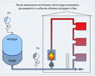
Expansion tank in an autonomous heating system.
In the absence of centralized heat supply in houses, autonomous heating systems are installed in which the coolant is heated by an individual low-power boiler. If the system communicates with the atmosphere through the expansion tank and the coolant circulates in it due to natural convection, it is called open. If there is no communication with the atmosphere, and the working medium circulates thanks to the pump, the system is called closed. As already mentioned, for the normal functioning of such systems, the water pressure in them should be approximately 1.5-2 atm. Such a low figure is due to the relatively short length of pipelines, as well as a small number of devices and fittings, resulting in a relatively low hydraulic resistance. In addition, due to the small height of such houses, the static pressure in the lower sections of the circuit rarely exceeds 0.5 atm.
At the stage of launching an autonomous system, it is filled with a cold coolant, maintaining a minimum pressure in closed heating systems of 1.5 atm. Do not sound the alarm if, after some time after filling, the pressure in the circuit drops. The pressure loss in this case is due to the release of air from the water, which was dissolved in it when the pipelines were filled. The circuit should be vented and completely filled with coolant, bringing its pressure to 1.5 atm.
After heating the coolant in the heating system, its pressure will increase slightly, while reaching the calculated operating values.
Precautionary measures

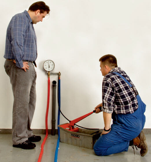
A device for measuring pressure.
Since when designing autonomous heating systems, in order to save money, a margin of safety is assumed to be small, even a low pressure jump of up to 3 atm can cause depressurization of individual elements or their connections. In order to smooth out pressure drops due to unstable operation of the pump or changes in the temperature of the coolant, an expansion tank is installed in a closed heating system. Unlike a similar device in an open type system, it does not have communication with the atmosphere. One or more of its walls are made of an elastic material, due to which the tank acts as a damper during pressure surges or water hammer.
The presence of an expansion tank does not always guarantee that the pressure is maintained within optimal limits. In some cases, it may exceed the maximum allowable values:
- with incorrect selection of the capacity of the expansion tank;
- in case of malfunction of the circulation pump;
- when the coolant overheats, which happens as a result of violations in the operation of the boiler automation;
- due to incomplete opening of shut-off valves after repair or maintenance work;
- due to the appearance of an air lock (this phenomenon can provoke both an increase in pressure and its fall);
- with a decrease in the throughput of the mud filter due to its excessive clogging.
Therefore, in order to avoid emergency situations when installing closed-type heating systems, it is mandatory to install a safety valve that will discharge excess coolant if the permissible pressure is exceeded.
Influence of coolant temperature
After the installation of heating equipment in a private house is completed, the coolant is pumped into the system. At the same time, the minimum possible pressure equal to 1.5 atm is created in the network. This value will increase in the process of heating the coolant, since, in accordance with the laws of physics, it expands. By changing the temperature of the coolant, you can adjust the pressure in the heating system.
It is possible to automate the control of the working pressure in the heating system by installing expansion tanks that do not allow an excessive increase in pressure. These devices are put into operation when a pressure level of 2 atm is reached. There is a selection of excess heated coolant by expansion tanks, due to which the pressure is kept at the desired level. It may happen that the capacity of the expansion tank is not enough to withdraw excess water. In this case, the pressure in the system approaches the critical bar, which is at the level of 3 atm. The situation is saved by a safety valve that allows you to keep the heating system intact by releasing it from the excess volume of coolant.
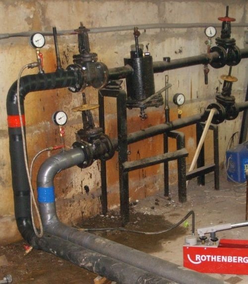
Insertion points for pressure gauges in the heating system: before and after the boiler, circulation pump, regulator, filters, mud collectors, as well as at the outlet of heating networks from the boiler room and at their entrance to houses
Causes of pressure rise and fall in the system
One of the most common causes of pressure drop in the heating system is the occurrence of a coolant leak. The “weak” links are most often the joints of individual parts. Although pipes can break through if they are already badly worn or defective. The presence of a leak in the pipeline is indicated by a drop in the level of static pressure, measured with the circulation pumps turned off.
If the static pressure is normal, then the fault must be sought in the pumps themselves. To facilitate the search for a leak, it is necessary to turn off various sections in turn, monitoring the pressure level. Having determined the damaged area, it is cut off from the system, repaired, sealing all joints and replacing parts with visible defects.
Elimination of visible coolant leaks after they are detected during an inspection of the heating system circuit of a private house or apartment
If the coolant pressure drops, and the leak cannot be found, then specialists are called. Using professional equipment, experienced craftsmen pump air into the system, previously freed from water, as well as cut off from the boiler and. By whistling air escaping through microcracks and loose connections, leaks are easily detected. If the pressure loss in the heating system is not confirmed, then proceed to check the health of the boiler equipment.
Use of professional equipment when searching for hidden leaks. Excess moisture detection scanner allows you to accurately determine the crack in the pipe
The reasons leading to a decrease in pressure in the system due to a malfunction of the boiler equipment include:
- accumulation of scale in the heat exchanger (typical for areas with hard tap water);
- the appearance of microcracks in the heat exchanger caused by physical wear and tear of the equipment, preventive flushes, factory defects;
- destruction of the bithermic heat exchanger that occurred during;
- damage to the chamber of the expansion tank of the heating boiler.
In each case, the problem is solved differently. Water hardness is reduced with the help of special additives. The damaged heat exchanger is soldered or changed. The tank built into the boiler is muffled, replacing it with an external device with suitable parameters. must be carried out by a suitably qualified engineer.
The reasons for the increase in pressure in the system:
- the movement of the coolant along the circuit is stopped (check the heating regulator);
- constant replenishment of the system, which occurs through the fault of a person or as a result of a failure of automation;
- shutting off a tap or valve in the direction of the coolant flow;
- education ;
- clogged filter or sump.
Having started the heating system, you should not wait for an instant normalization of the pressure level. For several days, air will be released from the coolant pumped into the system through automatic air vents or taps installed on the radiators. It is possible to restore the pressure of the coolant by its additional injection into the system. If this process is delayed for several weeks, then the cause of the pressure drop lies in the incorrectly calculated volume of the expansion tank or the presence of leaks.
1.
2.
3.
4.
5.
The heat supply structure of a large multi-storey building is a complex mechanism that can function effectively, provided that many parameters of the elements included in it are observed. One of them is the operating pressure in the heating system. Not only the quality of the heat transferred to the air depends on this value, but also the reliable and safe operation of the heating equipment.
The pressure in the heat supply system of multi-storey buildings must meet certain requirements and standards established and prescribed in SNiPs. If there are deviations from the required values, serious problems may occur, up to the inability to operate the heating system.
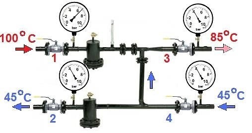
What does a large or small pressure difference between supply and return mean?
The normal difference between the pressure of the supply and return pipelines is 1-2 atmospheres. What does a change in this value in one direction or another mean?
- If the difference between the supply and return pressure is significant, then the system is almost at a standstill, possibly due to an air lock. It is necessary to find the cause and restore the circulation of the coolant;
- If it is much less in the heating system of your house, and tends to zero, then the movement of water through the pipes is disturbed. Most likely, water flows through nearby areas and does not reach remote areas, the adjustment is broken. But you need to take into account the fact that if the difference changes over time, and all the radiators warm up normally, the heating regulator may be to blame - the principle of its operation includes bypassing part of the water from the supply to the return, and perhaps the jump is due to the fact that just this cycle.
Indicators of normal pressure
As a rule, it is impossible to achieve the required parameters according to GOST, since various factors influence the performance indicators:
Equipment power
needed to supply the coolant. The pressure parameters in the heating system of a high-rise building are determined at heat points, where the coolant is heated for supply through pipes to radiators.
Equipment condition
. Both dynamic and static pressure in the heat supply structure are directly affected by the level of wear of boiler house elements such as heat generators and pumps.
Equally important is the distance from the house to the heat point.
The diameter of the pipelines in the apartment. If, when carrying out repairs with their own hands, the owners of the apartment installed pipes of a larger diameter than on the inlet pipeline, then the pressure parameters will decrease.
Location of a separate apartment in a high-rise building
Of course, the required pressure value is determined in accordance with the norms and requirements, but in practice it depends a lot on what floor the apartment is on and its distance from the common riser. Even when living rooms are located close to the riser, the onslaught of the coolant in the corner rooms is always lower, since there is often an extreme point of pipelines there.
The degree of wear of pipes and batteries
. When the elements of the heating system located in the apartment have served for more than a dozen years, then some reduction in equipment parameters and performance cannot be avoided. When such problems occur, it is advisable to initially replace worn pipes and radiators and then it will be possible to avoid emergency situations.
If the pressure drops
In this case, it is advisable to immediately check how the static pressure behaves (stop the pump) - if there is no drop, then the circulation pumps are faulty, which do not create water pressure. If it also decreases, then most likely there is a leak somewhere in the pipelines of the house, the heating main or the boiler house itself.
The easiest way to localize this place is by turning off various sections, monitoring the pressure in the system. If the situation returns to normal at the next cutoff, then there is a water leak on this section of the network. At the same time, take into account that even a small leak through a flange connection can significantly reduce the pressure of the coolant.
5. Piezometric graph
When designing and operating branched heating networks, a piezometric graph is widely used, on which the terrain, the height of the attached buildings, and the pressure in the network are plotted on a specific scale; it is easy to determine the pressure () and the available pressure (pressure drop) at any point in the network and subscriber systems using it.
On fig. 5.5 shows a piezometric graph of a two-pipe water heating system and a schematic diagram of the system. The level I - I, having a horizontal mark of 0, is taken as the horizontal plane of the pressure reference; , –
pressure schedule of the supply line of the network; , - pressure graph of the return line of the network; - total head in the return manifold of the heat supply source –
pressure developed by the network ohm 1;
H
st –
the total head developed by the make-up ohm, or, which is the same, the total static head of the heating network; H
To –
total head at point TO
on the discharge pipe a 1; –
pressure loss of network water in a heat treatment plant III
;
H
n
1 - full pressure in the supply manifold of the heat supply source: .
The available pressure of network water on the collectors. The pressure at any point of the heating network, for example, at the point 3,
denoted as follows: - total head at the point 3
supply line network; –
total head at point 3
return line of the network.
If the geodetic height of the pipeline axis above the reference plane at this point in the network is Z
3 , then the piezometric head at the point 3
supply line, and the piezometric head in the return line. Available pressure at the point 3
of the heating network is equal to the difference between the piezometric heads of the supply and return lines of the heating network or, which is the same, the difference in total heads .
Available pressure in the heating network at the subscriber's connection point D:
Head loss in the return line in this section of the heating network
In the hydraulic calculation of steam networks, the steam pipeline profile can be ignored due to the low steam density. The pressure drop in the steam pipeline section is assumed to be equal to the pressure difference at the end points of the section.The correct determination of the pressure loss, or pressure drop in pipelines, is of paramount importance for the selection of their diameters and the organization of a reliable hydraulic regime of the network.
To prevent erroneous decisions, before carrying out the hydraulic calculation of the water heating network, it is necessary to outline the possible level of static pressures, as well as the lines of maximum permissible maximum and minimum hydrodynamic pressures in the system and, guided by them, choose the nature of the piezometric graph from the condition that for any expected operating mode, the pressure at any point of the heat supply system do not go beyond the permissible limits. On the basis of a technical and economic calculation, it is only necessary to clarify the values of pressure losses, without going beyond the limits indicated by the piezometric graph. This design procedure makes it possible to take into account the technical and economic features of the object being designed.
The main requirements for the pressure regime of water heating networks from the condition of reliable operation of the heat supply system are as follows:
1) it is not allowed to exceed the allowable pressures in the equipment of the source, heating network and subscriber installations. Permissible excess (above atmospheric) in steel pipelines and fittings of heating networks depends on the used pipe assortment and in most cases is 1.6–2.5 MPa;
2) providing excess (above atmospheric) pressure in all elements of the heat supply system to prevent cavitation of pipes (network, make-up, mixing) and protect the heat supply system from air leakage. Failure to do so will result in corrosion of the equipment and disruption of water circulation. As the minimum value of overpressure, 0.05 MPa (5 m of water column) is taken;
3) ensuring non-boiling of network water in the hydrodynamic mode of the heat supply system, i.e. when water circulates in the system.
At all points of the heat supply system, it must be maintained that exceeds saturated water vapor at the maximum temperature of the network water in the system.
How to raise the pressure
Pressure checks in the heating lines of multi-storey buildings are a must. They allow you to analyze the functionality of the system. A drop in pressure level, even by a small amount, can cause serious failures.
In the presence of centralized heating, the system is most often tested with cold water. The pressure drop for 0.5 hours by more than 0.06 MPa indicates the presence of a gust. If this is not observed, then the system is ready for operation.
Immediately before the start of the heating season, a test is performed with hot water supplied under maximum pressure.
Changes occurring in the heating system of a multi-storey building, most often do not depend on the owner of the apartment. Trying to influence the pressure is a pointless undertaking. The only thing that can be done is to eliminate air pockets that have appeared due to loose connections or improper adjustment of the air release valve.
A characteristic noise in the system indicates the presence of a problem. For heating appliances and pipes, this phenomenon is very dangerous:
- Loosening of threads and destruction of welded joints during vibration of the pipeline.
- Termination of the supply of coolant to individual risers or batteries due to difficulties in de-airing the system, the inability to adjust, which can lead to its defrosting.
- A decrease in the efficiency of the system if the coolant does not stop moving completely.
To prevent air from entering the system, it is necessary to inspect all connections and taps for water leakage before testing it in preparation for the heating season. If you hear a characteristic hiss during a test run of the system, immediately look for a leak and fix it.
You can apply a soapy solution to the joints and bubbles will appear where the tightness is broken.
Sometimes the pressure drops even after replacing old batteries with new aluminum ones. A thin film appears on the surface of this metal from contact with water. Hydrogen is a by-product of the reaction, and by compressing it, the pressure is reduced.
Interfering with the operation of the system in this case is not worth it.
The problem is temporary and goes away on its own over time. This happens only in the first time after the installation of radiators.
You can increase the pressure on the upper floors of a high-rise building by installing a circulation pump.
Checking the tightness of the heating system
The tightness test is carried out in two stages:
- cold water test. Pipelines and batteries in a multi-storey building are filled with coolant without heating it, and pressure indicators are measured. At the same time, its value during the first 30 minutes cannot be less than the standard 0.06 MPa. After 2 hours, the loss cannot be more than 0.02 MPa. In the absence of gusts, the heating system of the high-rise building will continue to function without problems;
- test using a hot coolant. The heating system is tested before the start of the heating season. Water is supplied under a certain pressure, its value should be the highest for the equipment.
But residents of multi-storey buildings, if desired, can install such measuring instruments as pressure gauges in the basement and, in case of the slightest deviations in pressure from the norm, report this to the relevant utilities. If, after all the actions taken, consumers are still unhappy with the temperature in the apartment, they may need to consider organizing alternative heating.
GOST and SNiP requirements
In modern multi-storey buildings, the heating system is installed based on the requirements of GOST and SNiP. The regulatory documentation specifies the temperature range that central heating must provide. This is from 20 to 22 degrees C with humidity parameters from 45 to 30%.
To achieve these indicators, it is necessary to calculate all the nuances in the operation of the system even during the development of the project. The task of a heating engineer is to ensure the minimum difference in the pressure values of the liquid circulating in the pipes between the lower and last floors of the house, thereby reducing heat loss.
The following factors influence the actual pressure value:
- The condition and capacity of the equipment supplying the coolant.
- The diameter of the pipes through which the coolant circulates in the apartment. It happens that wanting to increase the temperature indicators, the owners themselves change their diameter upwards, reducing the overall pressure value.
- The location of a particular apartment. Ideally, this should not matter, but in reality there is a dependence on the floor, and on the distance from the riser.
- The degree of wear of the pipeline and heating devices. In the presence of old batteries and pipes, one should not expect that the pressure readings will remain normal. It is better to prevent the occurrence of emergency situations by replacing your old heating equipment.
Check the working pressure in a high-rise building using tubular deformation pressure gauges. If, when designing the system, the designers laid down automatic pressure control and its control, then sensors of various types are additionally installed. In accordance with the requirements prescribed in the regulatory documents, control is carried out in the most critical areas:
- at the coolant supply from the source and at the outlet;
- before the pump, filters, pressure regulators, mud collectors and after these elements;
- at the outlet of the pipeline from the boiler room or CHP, as well as at its entry into the house.
Please note: 10% difference between standard working pressure on the 1st and 9th floor is normal