New technology
In the domestic market, thermostats began to appear about 10 years ago, and replaced conventional taps and valves that simply blocked the conditional passage of the coolant. The disadvantage of this design is that by adjusting the amount of coolant that enters the radiator, you cannot control the temperature in the room for a long time. If an electric boiler has more or less stable operation, then a solid fuel boiler has a very high temperature range, and depends on the intensity of the combustion reaction. In this case, the temperature in the rooms will be either higher or lower, and the comfort for residents will be questionable.
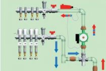
There is another important point from which the active introduction of thermostats began - work together with a warm floor. Now underfloor heating is the building norm, and a properly designed heating system is a combined system that consists of underfloor heating and radiator heating. At the same time, for the underfloor heating circuit, the temperature should be at the level of 20-25 degrees Celsius, and for heating through radiators - from 50 degrees.
The active introduction of thermostats began with the installation of underfloor heating
How to beat in this case, given that both the underfloor heating and the radiators work from the same boiler? The answer is to use a thermostat. The tap in this case will not solve the problem of supplying very hot water to the underfloor heating circuit. An easy way to deal with the distribution of heating is to install a thermostat at the inlet to the underfloor heating manifold, or use thermostats for each heating circuit.
The purpose of the thermostat for the water heater
In addition to all of the above, the thermostat is responsible for the safe operation of the boiler. To be more precise, when the water temperature rises, the pressure inside the sealed tank also rises, and if this growth is uncontrollable, then an explosion will soon occur. This can be dangerous not only for equipment, but also for human health, if you are nearby at this moment. The temperature regulator is a device through which the optimum temperature level is also maintained.
This is a kind of thermal valve that prevents:
- Overheat;
- Explosion;
- I damage not only equipment, but also nearby property.
It is he who is responsible for controlling the heating of water at the moment when the device is connected, and also for ensuring that the heating element is blocked in time. Almost every manufacturer seeks to supply the boiler with a thermostat. Products come in different models, however, they all have the same principle of operation. At the moment when you need to connect the equipment to the network, you need to immediately adjust the level of water heating.
Next, adjustable water heating is carried out, and the relay installed on the thermostat is responsible for opening the contacts of the heating element. When the tank is completely cooled down, the temperature drops below normal, and the contacts of the heating element of the relay close, due to which the system starts up, and the liquid in the tank heats up again.
DIY temperature controller power and load
As for the connection of the LM 335, it must be consistent. All resistances must be selected so that the total amount of current that passes through the temperature sensor corresponds to indicators from 0.45 mA to 5 mA. Exceeding the mark should not be allowed, as the sensor will overheat and show distorted data.

The thermostat can be powered up in several ways:
- Using a power supply with a focus on 12 V;
- With any other device, the power of which does not exceed the above figure, but the current flowing through the coil must not exceed 100 mA.
Let us remind you once again that the current in the sensor circuit should not exceed 5 mA, for this reason you will have to use a high power transistor. KT 814 is best. Of course, if you want to avoid using a transistor, you can use a relay with a lower current level. It can run on 220V.
Indoor control
Typical diagram of a temperature controller for a cellar.
Devices are indicated by Latin letters and numbers. For example, LM135. In order not to make a mistake in choosing, remember: 1 - use in military equipment, 2 - use in production apparatus and devices, 3 - use in household appliances. The Russian analogue is the designation of transistors - 2T (military) and CT (mass). The principle of operation of such a sensor is as follows: with an increase in temperature, the stabilization voltage increases, that is, it is a zener diode. You can verify the correct choice by reading the technical specifications of the device. The calibration point is in kelvins. The temperature scale is in degrees Celsius.
Remembering the school physics course, translate 0С= 0+273=273К. The operating range of the sensor is from -40 to 100°C. If such a sensor is used, there is no need for questionable experiments. It is enough to calculate the voltage at the output of the zener diode, and then specify this value as the master at the input of the comparator (comparison device). The LM335 temperature sensor is inexpensive - about 35-40 rubles. Based on this temperature sensor, draw a diagram of a thermostat for the cellar.
Schematic diagram of the thermostat.
In practice, it will be supplemented by an output device for turning on the heater, a power supply and an operation indicator.
The next important element is a comparator, for example LM311. It has two inputs - direct (2), marked "+", and inverse (3), marked "-", and one output. In the diagram, the output of the comparator is indicated by the number 7. This device works like this: the voltage at input 2 is greater than at input 3, we get a high level at the output. The transistor opened, connected the load. The potentiometer connected to the direct input sets the temperature - it sets the comparator threshold. In the opposite situation (the voltage at input 2 is less than at input 3), the output level decreases. The temperature rises, the thermal relay is activated, the comparator goes to a low level, the transistor closes, the heating element turns off. This cycle repeats itself continuously.
A simple do-it-yourself electronic thermostat. I propose a method for making a homemade thermostat to maintain a comfortable temperature in the room in cold weather. The thermostat allows you to switch power up to 3.6 kW. The most important part of any amateur radio design is the enclosure. A beautiful and reliable case will ensure a long life for any home-made device. In the version of the thermostat shown below, a convenient small-sized case and all power electronics are used from an electronic timer sold in stores. The self-made electronic part is built on the LM311 comparator chip.
DIY temperature controller details
The temperature sensor is usually a thermistor - an element whose electrical resistance changes depending on temperature. Semiconductor elements are also used - transistors and diodes, the characteristics of which are also affected by temperature: when heated, the collector current (for transistors) increases, while a shift in the operating point is observed and the transistor stops working without responding to the input signal.
 But such sensors have a significant drawback: they are quite difficult to calibrate, that is, “bind” to certain temperature values, which is why the accuracy of a home-made thermostat leaves much to be desired.
Meanwhile, the industry has long mastered the production of inexpensive thermal sensors, the calibration of which is carried out in the manufacturing process.
These include the LM335 brand device from National Semiconductor, which we recommend using. The cost of this analog thermal sensor is only $1.
"Three" in the first position of the digital row in the marking means that the device is focused on use in household appliances. Modifications LM235 and LM135 are intended for use in industry and in the military, respectively.
With 16 transistors, this sensor works like a zener diode. Moreover, its stabilization voltage depends on temperature.
The dependence is as follows: for each degree on an absolute scale (in Kelvin), there is 0.01 V of voltage, that is, at zero Celsius (273 Kelvin), the stabilization voltage at the output will be 2.73 V. The manufacturer calibrates the sensor at a temperature of 25C (298K ). The operating range lies in the range from -40 to +100 degrees Celsius.
 Thus, when assembling a thermostat based on the LM335, the user gets rid of the need to select, by trial and error, the reference voltage at which the device will provide the required temperature.
It can be calculated using a simple formula:
Where T is the temperature of interest to the user on the Celsius scale.
In addition to the temperature sensor, we need a comparator (an LM311 brand from the same manufacturer is suitable), a potentiometer for generating a reference voltage (setting the required temperature), an output device for connecting a load (relay), indicators and a power supply.
The thermostat is an integral part of autonomous heating. The thermostat for the heating boiler will help maintain the temperature in the house at a comfortable level.
We will analyze the principle of operation of the thermostat for an infrared heater here.
Is it worth installing a thermostat for a heating radiator? In this article http://microklimat.pro/otopitelnoe-oborudovanie/otopitelnye-pribory/termoregulyator-dlya-radiatora-otopleniya.html we will consider the purpose of the device and the types and features of installation.
In ancient times
 In the first household and industrial incubators of the last century, the temperature was controlled using bimetallic relays. To remove the load and eliminate the influence of overheating of the contacts, the heaters were switched on not directly, but through powerful power relays. This combination can be found in cheap models to this day. The simplicity of the circuit was the key to reliable operation, and any high school student could make such a thermostat for an incubator with his own hands.
All the positive aspects were negated by the low resolution and the complexity of the adjustment. The temperature in the process must be reduced according to the schedule in increments of 0.5 ° C, and it is very problematic to do this precisely with the adjusting screw on the relay located inside the incubator. As a rule, the temperature remained constant throughout the entire period of incubation, which led to a decrease in hatchability. Designs with an adjusting knob and a graduated scale were more convenient, but the retention accuracy was reduced by ± 1-2 ° C.
Types of thermal relay
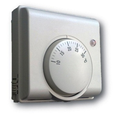
A conventional thermostat is a small electronic unit that is mounted on a wall in a suitable place and connected to a heat source by wires. On the front panel there is only a temperature controller, this is the cheapest kind of device.
In addition to it, there are other types of thermal relays:
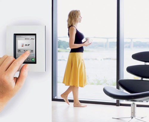
- programmable: they have a liquid crystal display, are connected using wires or use a wireless connection with the boiler. The program allows you to set the temperature change at certain hours of the day and by day during the week;
- the same device, only equipped with a GSM module;
- autonomous regulator powered by its own battery;
- wireless thermostat with remote sensor to control the heating process depending on the ambient temperature.
Multifunctional thermal relays that can be programmed significantly save energy. During those hours of the day when no one is at home, it makes no sense to maintain a high temperature in the rooms.Knowing the working schedule of his family, the homeowner can always program the temperature switch so that at certain hours the air temperature drops, and the heating is turned on an hour before people arrive.
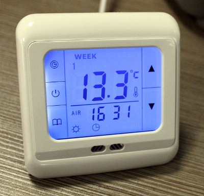
Household thermostats, equipped with a GSM module, are able to provide remote control of the boiler plant via cellular communication. Budget option - sending notifications and commands in the form of SMS - messages from a mobile phone. Advanced versions of devices have their own applications installed on a smartphone.
Main types of boilers and temperature control
There are several types of boilers: solid fuel, gas, electric and liquid fuel.
Boilers are widely used all over the world. There are domestic samples, there are boilers and imported ones. The material of manufacture is steel or cast iron. Easy to operate, economical, with the function of adjusting the temperature of the coolant. In cheaper models, this function is implemented using a special device - a thermocouple.
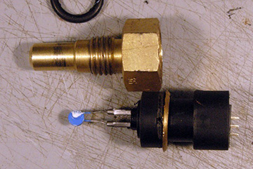
Structurally, a thermoelement is a metal product, the geometric dimensions of which, under the influence of temperatures, decrease or increase (depending on the degree of heating). And from this, in turn, the position of the special lever changes, which closes and opens the draft damper. The photo shows an example of such a regulator:
Photo: sample thermostat
The more the damper is open, the stronger the combustion process, and vice versa. Thus, the volume of air that enters the closed-type combustion chamber is fully controlled by the thermostat, and if necessary, its supply is stopped and the combustion process dies out. In more modern models, controllers are installed that, depending on the specified thermal conditions, control the air flow, turning on (or turning off) a special fan (see photo below):
Boiler with temperature controller
Gas boilers are the most common and cheapest units to operate. Boilers are single-circuit and double-circuit. Single-circuit boilers have one heat exchanger and are intended for heating only. The switching circuit is shown in the figure below:
Scheme of switching on a single-circuit boiler
Double-circuit boilers have two heat exchangers and are designed for heating and hot water production. The boiler connection diagram is shown below:
Scheme of switching on a double-circuit boiler
Some boilers have separate controls for heating and hot water temperature.
Setting the thermostat
As already mentioned, the thermostat based on the LM335 sensor does not need to be configured. It is enough to know the voltage supplied by the potentiometer to the direct input of the comparator.
You can measure it with a voltmeter. The required voltage value is determined by the above formula.
If it is necessary, for example, for the device to operate at a temperature of 20 degrees, it should be 2.93 V.
If any other element is used as a temperature sensor, the reference voltage will have to be checked empirically. To do this, you must use a digital thermometer, for example, TM-902C. For precise adjustment, the sensors of the thermometer and thermostat can be connected with electrical tape, after which they are placed in an environment with different temperatures.
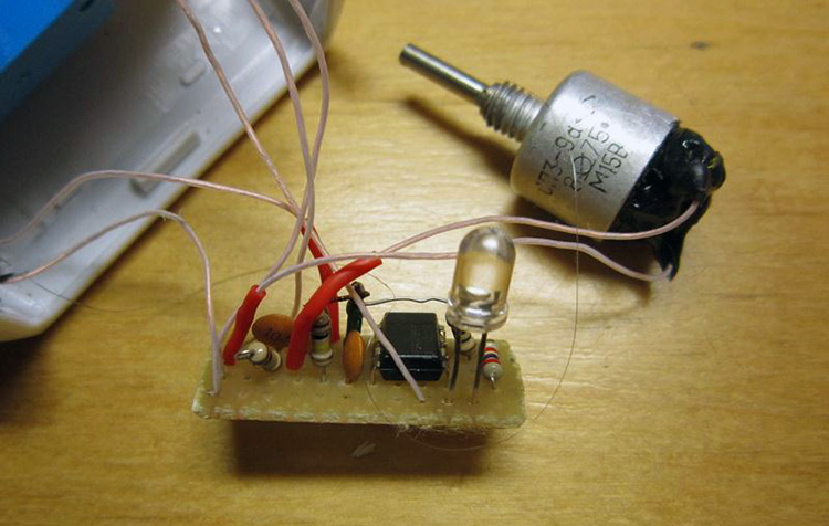
Thermostat from improvised materials
The potentiometer knob must be rotated smoothly until the thermostat works. At this point, you should look at the scale of the digital thermometer and apply the temperature displayed on it to the scale of the thermostat. You can define extreme points, for example, for temperatures of 8 and 40 degrees, and mark intermediate values by dividing the range into equal parts.
If there is no digital thermometer at hand, extreme points can be determined by water with ice floating in it (0 degrees) or by boiling water (100 degrees).
Faced with the choice of a heater, people find that there are many types of appliances, but you need to choose one. Ceramic heater for the home - the subtleties of the right choice, an overview of models and prices.
The norms of air humidity and how to measure it are presented in this topic.
Principle of operation
The temperature sensor delivers electrical impulses, the current value of which depends on the temperature level. The inherent ratio of these values allows the device to very accurately determine the temperature threshold and decide, for example, how many degrees the air supply damper to the solid fuel boiler should be opened, or the hot water supply damper should be open. The essence of the operation of the thermostat is to convert one value to another and correlate the result with the current level.
Simple home-made regulators, as a rule, have a mechanical control in the form of a resistor, by moving which, the user sets the required temperature threshold, that is, indicating at what outside temperature it will be necessary to increase the supply. With more advanced functionality, industrial devices can be programmed to wider limits, using a controller, depending on various temperature ranges. They do not have mechanical controls, which contributes to long work.
What parts do you need a do-it-yourself thermostat
For a temperature sensor, a thermistor is most often used, this is an element that regulates electrical resistance depending on the temperature indicator.
Semiconductor parts are also often used:
- Diodes;
- Transistors.
The temperature should have the same effect on their characteristics. That is, when heated, the transistor current should increase and at the same time it should stop working, despite the incoming signal. It should be noted that such details have a big drawback. It is too difficult to calibrate, to be more precise, it will be difficult to link these parts to some temperature sensors.
However, at the moment the industry does not stand still, and you can see devices from the 300 series, this is the LM335, which is increasingly recommended by experts and the LM358n. Despite the very low cost, this part occupies the first position in the markings and focuses on combination with household appliances. It is worth mentioning that modifications of this part LM 235 and 135 are successfully used in the military and industry. Including about 16 transistors in its design, the sensor is able to work as a stabilizer, and its voltage will completely depend on the temperature indicator.
The dependency is as follows:
- For each degree, there will be about 0.01 V, if you focus on Celsius, then for an indicator of 273 the output result will be 2.73V.
- The operating range is limited in terms of -40 to +100 degrees. Thanks to such indicators, the user completely gets rid of adjustments by trial and error, and the required temperature will be provided in any case.
Also, in addition to the temperature sensor, you will need a comparator, it is best to purchase an LM 311, which is produced by the same manufacturer, a potentiometer in order to form a reference voltage and an output setting to turn on the relay. Do not forget to purchase a power supply and special indicators.
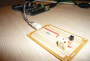
Digital thermostat
In order to create a fully functioning thermostat with accurate calibration, digital elements are indispensable. Consider a temperature control device for a small vegetable store.
The main element here is the PIC16F628A microcontroller. This chip provides control of various electronic devices. The PIC16F628A microcontroller contains 2 analog comparators, an internal oscillator, 3 timers, SSR comparison and USART data exchange modules.
When the thermostat is operating, the value of the existing and set temperature is fed to the MT30361 - a three-digit indicator with a common cathode. In order to set the required temperature, the buttons are used: SB1 - to decrease and SB2 - to increase. If you carry out tuning while pressing the SB3 button, you can set the hysteresis values. The minimum hysteresis value for this circuit is 1 degree. A detailed drawing can be seen on the plan.
It is used in many technological processes, including domestic heating systems. The factor determining the operation of the thermostat is the outside temperature, the value of which is analyzed and when the set limit is reached, the flow rate is reduced or increased.
Thermoregulators come in various designs and today there are a lot of industrial versions on sale that work according to different principles and are intended for use in different areas. Also available are the simplest electronic circuits, which anyone can assemble with the appropriate knowledge of electronics.
Do-it-yourself thermostat scheme
About the design of the thermostat, we can say that it is not particularly complicated, it is for this reason that most radio amateurs begin their training with this device, and it is also on it that they hone their skills and craftsmanship. You can find a very large number of device circuits, but the most common is a circuit using the so-called comparator.

This element has several inputs and outputs:
- One input corresponds to the supply of a reference voltage that corresponds to the required temperature;
- The second receives voltage from the temperature sensor.
The comparator itself takes all incoming readings and compares them. If it generates an output signal, it will turn on the relay, which will supply current to the heating or refrigeration unit.
Homemade external thermostat for the boiler instruction
Below is a diagram of a home-made thermostat for a boiler, which is assembled on Atmega-8 and 566 series microcircuits, a liquid crystal display, a photocell and several temperature sensors. The programmable Atmega-8 chip is responsible for compliance with the set parameters of the thermostat settings.
Scheme of a homemade external thermostat for the boiler
In fact, this circuit turns the boiler on or off when the outside temperature drops (rises) (sensor U2), and also performs these actions when the temperature in the room changes (sensor U1). Adjustment of the work of two timers is provided, which allow you to adjust the time of these processes. A piece of circuit with a photoresistor affects the process of turning on the boiler according to the time of day.
Sensor U1 is located directly in the room, and sensor U2 is outside. It is connected to the boiler and installed next to it. If necessary, you can add the electrical part of the circuit, which allows you to turn on and off high-power units:
The electrical part of the circuit, which allows you to turn on and off high power units
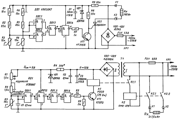
Another thermostat circuit with one control parameter based on the K561LA7 chip:
Scheme of a thermostat with one control parameter based on the K561LA7 microcircuit
The assembled thermostat based on the K651LA7 chip is simple and easy to adjust. Our thermostat is a special thermistor that significantly reduces resistance when heated. This resistor is connected to the electricity voltage divider network. This circuit also has a resistor R2, with which we can set the required temperature. Based on such a scheme, you can make a thermostat for any boiler: Baksi, Ariston, Evp, Don.
Another circuit for a thermostat based on a microcontroller:
Scheme for a thermostat based on a microcontroller
The device is assembled on the basis of the PIC16F84A microcontroller. The role of the sensor is performed by a digital thermometer DS18B20. A small relay controls the load. Microswitches set the temperature that is displayed on the indicators. Before assembly, you will need to program the microcontroller. First, erase everything from the chip and then reprogram, and then assemble and use it to your health. The device is not capricious and works fine.
The cost of parts is 300-400 rubles. A similar regulator model costs five times more.
A few last tips:
- although different versions of thermostats are suitable for most models, it is still desirable that the thermostat for the boiler and the boiler itself be produced by the same manufacturer, this will greatly simplify the installation and the operation process itself;
- before buying such equipment, you need to calculate the area of \u200b\u200bthe room and the required temperature in order to avoid “downtime” of equipment, and changing wiring due to the connection of devices of higher power;
- before installing the equipment, you need to take care of the thermal insulation of the room, otherwise high heat losses will be inevitable, and this is an additional expense item;
- if you are unsure that you need to purchase expensive equipment, then you can conduct a consumer experiment. Get a cheaper mechanical thermostat, adjust it and see the result.
General concept of temperature controllers
Devices that fix and simultaneously regulate the set temperature value are more common in production. But they also found their place in everyday life. To maintain the necessary microclimate in the house, thermostats for water are often used. With their own hands they make such devices for drying vegetables or heating an incubator. Such a system can find its place anywhere.
In this video, we will learn what a temperature controller is:
In fact, most thermostats are only part of the overall scheme, which consists of the following components:
- A temperature sensor that measures and fixes, as well as transmits the information received to the controller. This happens due to the conversion of thermal energy into electrical signals that are recognized by the device. A resistance thermometer or a thermocouple can act as a sensor, which in their design have a metal that reacts to temperature changes and changes its resistance under its influence.
- The analytical block is the regulator itself. It receives electronic signals and reacts depending on its functions, after which it transmits a signal to the actuator.
- An actuator is a kind of mechanical or electronic device that, when receiving a signal from the unit, behaves in a certain way. For example, when the set temperature is reached, the valve will shut off the coolant supply. Conversely, as soon as the readings fall below the set values, the analytical unit will give a command to open the valve.
Homemade thermostat step by step instructions
If you have purchased all the necessary components for assembly, it remains to consider the detailed instructions. We will consider the example of a temperature sensor designed for 12V.
A homemade temperature controller is assembled according to the following principle:
- We prepare the body. You can use old shells from the counter, for example, from the Granit-1 installation.
- You select the scheme that you like best, but you can also orient yourself on the board from the meter. The forward stroke marked “+” is required to connect a potentiometer, the inverted input marked “–” will be used to connect a temperature sensor. If it so happens that the voltage at the direct input is higher than required, a high mark will be set at the output and the transistor will begin to supply power to the relay, and it, in turn, to the heating element.As soon as the output voltage exceeds the allowable mark, the relay will turn off.
- In order for the thermostat to work on time and temperature differences to be provided, it will be necessary to make a negative type connection using a resistor, which is formed between the direct input and the output on the comparator.
- As for the transformer and its power supply, an induction coil from an old electric meter may be needed here. In order for the voltage to correspond to 12 volts, you will need to make 540 turns. It will be possible to fit them only if the diameter of the wire is no more than 0.4 mm.
That's all. All the work on creating a thermostat with your own hands lies in these small actions. It is possible that you yourself will not be able to do it right away without certain skills, however, based on photo and video instructions, you can test all your skills.
Thanks to its simple design, the self-made thermocontroller can be used anywhere.
For instance:
- For a warm floor;
- For the cellar;
- May be able to adjust the air temperature;
- For the oven;
- For an aquarium where it will control the temperature of the water;
- In order to control the temperature value of the electric boiler pump (turn it on and off);
- And even for a car.
It is not necessary to use a digital, electronic or mechanical commercial thermal switch. Having bought an inexpensive thermal relay, make power adjustments on the triac and thermocouple and your home-made device will work no worse than the purchased one.
DIY repair
Assembled by hand, these devices last a long time, but there are several standard situations when repairs may be required:
- Failure of the adjusting resistor - happens most often, since the copper tracks wear out, inside the element along which the electrode slides, it is solved by replacing the part.
- Overheating of the thyristor or triode - the power was incorrectly selected or the device is located in a poorly ventilated area of \u200b\u200bthe room. In order to avoid this in the future, thyristors are equipped with radiators, or the thermostat should be moved to a zone with a neutral microclimate, which is especially important for wet rooms.
- Incorrect temperature control - possible damage to the thermistor, corrosion or dirt on the measuring electrodes.
Quality materials to get the job done
You will need:
- potentiometer;
- integral stabilizer;
- network adapter;
- output device;
- thermostat.
Nowadays, any device can be bought in a store, but sometimes it is cheaper to make it yourself. Naturally, it is not worth soldering spare parts for electrical appliances, but it is quite possible to make an individual device that fits the parameters of your cellar. The scheme of such a device is simple. A certain temperature is maintained by turning on / off the heating element (TENA).
The temperature rises to a predetermined level, a special device is triggered - a comparator, the heating element turns off. In theory, such a device is easy to make, but when it comes to practical implementation, it becomes clear that not everything is so simple. Previously, calibration was performed as follows: the temperature sensor was first immersed in ice, then in boiling water.
To measure the readings, we took a voltmeter and a thermometer and set the desired response temperature. The process took a lot of time and gave not the best results. Today, buying a temperature sensor is not a problem. They are calibrated at the time of manufacture, so there is no need to carry out any experiments. Modern technologies have made it possible to create such a temperature sensor that transmits digital information.With the help of these devices, it is possible to measure the temperature at various points in the apartment - you control the temperature not only outside the window, but also inside the house.
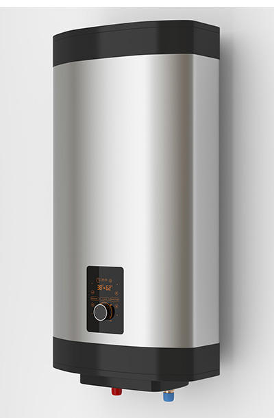
Electric boilers
A fairly common alternative to gas and solid fuel boilers. A lot of advantages, high efficiency, but a long payback period. The connection is simple, like with gas boilers, but without a cold water supply. Temperature control and overheating protection are provided.
Boiler mechanical timer
With a simple mechanical timer for an electric boiler, there are three options for starting the central heating system:
- The boiler is off;
- The boiler supplies hot water;
- The boiler turns on and off at the set time.
Mechanical timers usually have a large round dial with a 24-hour scale in the center. By turning the dial, you can set the desired time and then leave it at that position. The boiler will turn on at the right time. The outer part consists of a set of tabs with a 15-minute period, which are inserted for the convenience of adjusting the operation and setting modes. An emergency reconfiguration is possible, which is performed when the boiler is connected to the network.
Mechanical timers are easy to set, but the boiler always turns on and off at the same time every day, and this may not satisfy the owners if the family is large and bath procedures are performed several times a day at different times.
Circuit with logic chip
This circuit differs from the previous one in that instead of a zener diode, it uses a K561LA7 logic chip. The temperature sensor is still a thermistor (designation - VDR1), only now the decision to close the circuit is made by the logical unit of the microcircuit. By the way, the K561LA7 brand has been produced since Soviet times and costs mere pennies.
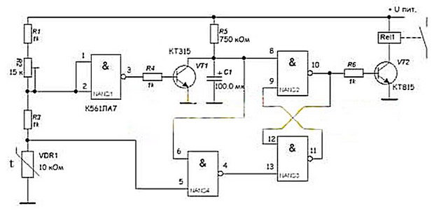
For intermediate amplification of the pulses, the KT315 transistor is used, for the same purpose, a second transistor, KT815, is installed in the final stage. This diagram corresponds to the left side of the previous one, the power block is not shown here. As you might guess, it can be similar - with the KU208G triac. The operation of such a home-made thermal relay has been tested on ARISTON, BAXI, Don boilers.
How to connect and adjust the thermostat for a water heater
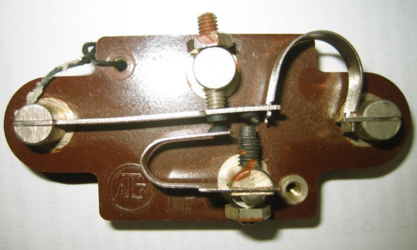
If the boiler does not work, then you do not need to start it again, waiting for a phenomenal turn-on, but check the product for breakdowns. If it is found that the problem is in the thermostat, then a replacement is required. Repair does not cover the sensor and, as a rule, they simply purchase a new part. How to replace the thermostat?
You don’t need a master, just don’t violate the instructions below:
- The water heater is disconnected from the network.
- The valve is closed with the supply of water to the tank capacity, and all the liquid in it is drained.
- The lower panel of the device is removed, which allows you to get close to the heating element.
- Next, the pressure ring in the heating element is removed.
- The sensor in the thermostat and the control unit are removed.
- A new thermostat is being installed.
- In place, be sure to install the clamping ring and secure the bottom panel.
A couple of not complicated movements, and a maximum of money, time and effort is saved. In order to choose a protective thermostat for a water heater, you should follow certain recommendations from experts. Going to purchase a new thermostat, it is worth taking a technical passport for the boiler with you. So it will be much easier for the seller to figure out which model and with what operational features it is best suited. It is strictly forbidden to throw away a broken product before buying a new one.
You need to choose a thermostat of exactly the same model, since a minimal difference in size or characteristics can lead to a breakdown of the entire boiler.When choosing a thermostat on your own, you need to focus on the type of product, parameters, installation method, on what it has a working current and functionality.