Device and types
A thermistor is a semiconductor device whose resistance depends on its temperature. Depending on the type of element, the resistance may rise or fall as it heats up. There are two types of thermistors:
- NTC (Negative Temperature Coefficient) - with a negative temperature coefficient of resistance (TCR). They are often referred to as "Thermistors".
- PTC (Positive Temperature Coefficient) - with a positive TCS. They are also called "Pozistors".
Important! The temperature coefficient of electrical resistance is the dependence of resistance on temperature. Describes how many ohms or percent of the nominal value the resistance of the element changes when its temperature rises by 1 degree Celsius
For example, conventional resistors have a positive TCR (when heated, the resistance of the conductors increases).
Thermistors are low-temperature (up to 170K), medium-temperature (170-510K) and high-temperature (900-1300K). The body of the element can be made of plastic, glass, metal or ceramic.
The symbolic graphic designation of thermistors in the diagram resembles ordinary resistors, and the only difference is that they are crossed out with a stripe and the letter t is indicated next to it.
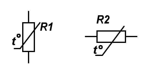
By the way, this is how any resistors are designated, the resistance of which changes under the influence of the environment, and the type of influencing quantities is indicated by the letter, t is temperature.
Main characteristics:
- Rated resistance at 25 degrees Celsius.
- Maximum current or power dissipation.
- Operating temperature range.
- TKS.
Interesting fact: The thermistor was invented in 1930 by scientist Samuel Ruben.
Let's take a closer look at how it works and what each of them is for.
measurements
|
|
|||||
|
To measure temperature, semiconductor diodes and transistors can be used as thermal converters. This is because at a constant value of current flowing in the forward direction, for example, through the junction of a diode, the voltage at the junction changes almost linearly with temperature. In order for the current value to be constant, it is enough to include a large active resistance in series with the diode. In this case, the current passing through the diode should not cause it to heat up. It is possible to build a calibration characteristic of such a temperature sensor using two points - at the beginning and at the end of the measured temperature range. Figure 1, a shows the temperature measurement circuit using the VD diode. A battery can serve as a power source.
Rice. 1. Scheme for measuring temperature using a diode (a) and transistors (b, c). Bridge pickups allow you to increase the relative sensitivity of the device by compensating the initial value of the sensor resistance. Similarly, temperature affects the resistance of the emitter-base transition of transistors. In this case, the transistor can simultaneously act both as a temperature sensor and as an amplifier of its own signal. Therefore, the use of transistors as thermal sensors has an advantage over diodes. Figure 1b shows a thermometer circuit in which a transistor (germanium or silicon) is used as a temperature converter. In the manufacture of thermometers both on diodes and on transistors, it is required to build a calibration characteristic, while a mercury thermometer can be used as an exemplary measuring instrument. The inertia of thermometers on diodes and transistors is small: on a diode - 30 s, on a transistor - 60 s. Of practical interest is a bridge circuit with a transistor in one of the arms (Fig. 1, c). In this circuit, the emitter junction is included in one of the arms of the bridge R4, a small blocking voltage is applied to the collector.
Key tags: diode, transistor, temperature |
|||||
|
|||||
|
|||||

Diode as temperature sensor - semiconductor function
A diode is the simplest device in its configuration that has the properties of a semiconductor.
Between the two extremes of the diode (donor and acceptor) lies the space charge region, otherwise: p-n-junction. This “bridge” ensures the penetration of electrons from one part to another, therefore, due to the different names of its constituent charges, a rather small, but still, current appears inside the diode. The movement of electrons through the diode occurs only in one direction. Of course, there is a reverse motion, but it is completely insignificant, and when you try to connect a power source in this direction, the diode is blocked by reverse voltage. This increases the density of the substance and diffusion occurs. By the way, it is for this reason that the diode is called a semiconductor valve (there is movement in one direction, but not in the other).
If you try to increase the temperature of the diode, then the number of minority carriers (electrons moving in the opposite direction to the main direction) will increase, and the p-n junction will begin to collapse.
The principle of interaction between the voltage drop across the diode p-n junction and the temperature of the diode itself was revealed almost immediately after it was designed.
As a result, the p-n junction of a silicon diode is the simplest temperature sensor. Its TKV (voltage temperature coefficient) is 3 millivolts per degree Celsius, and the forward voltage drop point is about 0.7V.
For normal operation, this voltage level is unnecessarily low, therefore, not the diode itself is often used, but transistor p-n junctions complete with a basic voltage divider.
As a result, the design in its qualities corresponds to the whole sequence of diodes. As a result, the voltage drop indicator can be much larger than 0.7V.
Since the TCR (temperature coefficient of resistance) of the diode is negative (-2mV / ° C), it turned out to be very relevant for use in varicaps, where it plays the role of a stabilizer of the resonant frequency of the oscillatory circuit. Controlled by temperature.
Diode voltage drop data
When analyzing the readings of a digital multimeter, it can be noted that the data on the voltage drop across the p-n junction for silicon diodes is 690-700 mV, and for germanium - 400-450 mV (although this type of diode is practically not used at the moment). If during the measurement the temperature of the diode rises, then the multimeter data, on the contrary, will decrease. The greater the heating force, the greater the drop in digital data.
Usually this property is used to stabilize the process of work in an electronic system (for example, for audio frequency amplifiers).
Scheme of a thermometer on a diode.
Temperature sensors for microcontroller
At the moment, many circuits are built on microcontrollers, and various temperature meters can also be included here, in which semiconductor sensors can be used, provided that the temperature during their operation does not exceed 125 ° C.
Since the temperature meters are calibrated at the factory, there is no need to calibrate and adjust the sensors.The results obtained from them in the form of digital data are fed to the microcontroller.
The application of the received information depends on the software content of the controller.
Among other things, such sensors can operate in a thermostatic mode, that is (with a predetermined program) turn on or off when a certain temperature is reached.
However, if other temperature indicators become reference, the program will have to be rewritten.
Other applications
Although today the choice of temperature sensors is very wide, no one forgets about their diode version, which is often used in electric irons, electric fireplaces and electronics in its broadest sense.
Despite the limitations in temperature conditions, diode sensors have their significant advantages:
- relative cheapness;
- modest dimensions;
– easily fit a huge number of electronic devices;
- excellent sensitivity and accuracy.
Thanks to all these qualities, the field of application of sensors of this type is growing from year to year.
Write comments, additions to the article, maybe I missed something. Take a look at the sitemap, I will be glad if you find something else useful on my site.
A simple electronic thermometer on a unijunction transistor
category
Radio circuits for home
I. Nechaev. KurskRadio, 1992, No. 8, pp. 17-18
In this article, we will talk about the possibility of designing devices for measuring temperature at a distance - outside the house or, say, in a balcony “vegetable store”. There are a lot of schemes that allow you to perform this function, but there are certain features when choosing a temperature-sensitive sensor.
As a rule, in most cases, when designing such devices, thermistors are most often used by radio amateurs. They have a fairly wide thermal resistance coefficient (hereinafter referred to as TCR) - up to 8% per degree. However, it varies greatly in the zone of measured temperatures. If for home thermometers you can close your eyes to this fact, then if we are talking about a wide temperature range (for example, as in our case, from - 40 degrees C to + 40 degrees C), then certain problems arise with the graduation of the measuring scale device, it will simply lose its linearity.
We also know that the most common p-n junction of any semiconductor device can serve as a temperature sensor, however, the TCH of a simple junction is very small - no more than 0.3% per degree, and this requires the introduction of additional amplifying circuits, which greatly complicates the design.
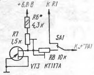
As experience has shown, unijunction transistors of the KT117 type are best suited for use as a temperature sensor (they were used in the power supplies of 2 \ 3 USCT TVs and it will not be difficult to find them) if you connect it as shown in the picture
As a result of such inclusion, we obtain a thermistor with a resistance of 5 ... 10 kOhm with a CTS of approximately 0.7 ... 0.9% per degree C. In this case, the scale of the device will be linear over the entire temperature range. This property of a unijunction transistor made it possible to use it as a temperature sensor in a device, the circuit of which is shown in the figure.
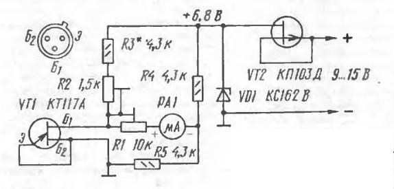
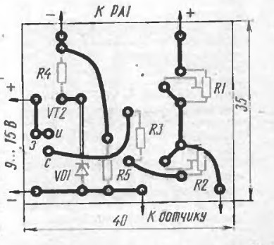
The basis of the considered electronic thermometer is a measuring bridge on resistors R2-R5 in one arm of which a unijunction transistor VT1 is connected. A PA1 microammeter with zero in the middle is installed in the diagonal of the bridge. A full-wave rectifier can serve as a power source; for this purpose, a parametric stabilizer on a VT2 transistor and a VD1 zener diode is introduced into the circuit. If the device will be operated for a short time (turned on, looked, turned off), then a 9-volt battery of the “Krona” type can also be used, in which case the stabilization circuits can be excluded from the circuit.
The essence of the device is as follows: all resistors in the circuit are fixed, only the resistance of the temperature sensor, the role of which is played by the transistor, is variable.When the ambient temperature changes, the current through the temperature sensor will change. Moreover, the current will change both upwards with an increase in temperature, and downwards with a decrease in temperature. It turns out that it remains only by selecting the resistors of the measuring bridge and adjusting the tuning resistor R1 to set the readings of the instrument arrow to zero at 0 degrees C.
When setting up the device, you can use the following recommendations - melting ice from the refrigerator can be used as a reference for "zero" temperature. It is also not difficult to get a temperature of 40 ... 50 degrees C. You can simply heat the oven to the desired temperature. Thus, you can set the zero position of the device and the maximum positive by making the appropriate marks on the scale. The “minus” mark can be made at the same distance as the “plus” mark, because the measurement scale will be linear.
All parts of the thermometer are mounted on a printed circuit board made of one-sided foil textolite, a sketch of which is shown in the figure.
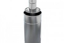
An approximate appearance of the device is shown in the following figure.
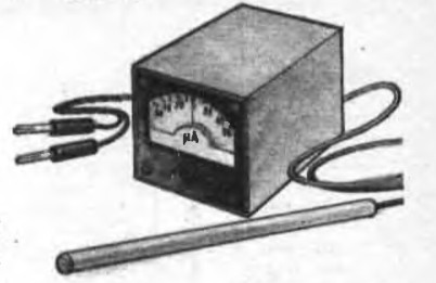
For this thermometer, a microammeter of the M4206 type for a current of 50 μA with a zero in the middle of the scale is best suited. If suddenly this device was not available, then you can use any other microammeter for the specified current (preferably with a large measuring scale), but then an additional button will need to be introduced into the circuit so that it is possible to control positive and negative temperatures separately, as shown in the figure
Well, in the end: if necessary, the device can be equipped with several temperature sensors by turning them on according to the following scheme
Thus, we will be able to control the temperature in several objects - for example, at home and on the street.
Thermal sensors on transistors in MK circuits
The physical nature of semiconductor materials is such that their parameters depend quite strongly on temperature. In conventional amplifying circuits, this phenomenon is fought, while in temperature meters, on the contrary, they are encouraged. For example, in silicon transistors with a constant collector current, with increasing temperature, the base-emitter voltage U^^^ decreases with a theoretical coefficient of 2.1 mV / ° C. The actual change is proportional to the ratio 1000|mV|/Gx1 K], where Gx is the medium temperature on the Kelvin scale.
Calculation example. Let the voltage between the base and emitter of a standard silicon transistor at a temperature of 7;) = 20°C be ^^^
With an increase in the temperature of its case to G, \u003d 35 ° C, this voltage decreases by 49m V: i
The actual voltage may differ slightly from the calculated one, depending on the position of the operating point of the transistor and its type. In any case, it is recommended to reduce and stabilize the current flowing through the /?-/7-junction in order to eliminate the effect of self-heating of the crystal.
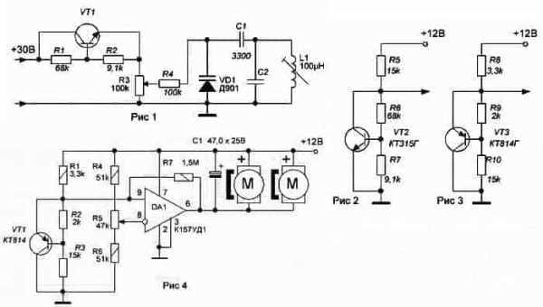
Rice. 3.67. Schemes for connecting transistor thermal sensors to MK:
a) temperature measurement in the range of -30…+150°C. The temperature sensor is the VTI transistor, in which the voltage (/[^e "drifts" with a coefficient of about 2 mV / ° C. Resistors R4 and 7 set the temperature range and +3 V calibration voltage at the MK input at room temperature + 25 ° C. Transistor VTI has a metal case, the end of which can be pressed into a heat-resistant plastic tube and the entire structure can be used as an external probe or probe;
b) a temperature sensor based on a single-junction transistor VTI provides linearity of temperature measurement in the range of 0…+ 100°С;
c) The VTI transistor is specially used small-sized surface-mounted (SMD). This is necessary to reduce the thermal inertia of the sensor. For example, an SMD transistor enters a stable thermal regime one minute after a temperature jump of 10 ° C (a typical “large” transistor takes several times longer).Resistor /^/ balances differential circuit consisting of transistors VTI, VT2\
On Fig. 3.67, a ... d shows the connection diagrams of transistor thermal sensors to the MK.
d) transistor VT1 has a hole in its body, through which it can be fixed with a screw on the surface of the object being measured. The collector of the transistor is electrically connected to its body, which must be taken into account during installation. The temperature conversion coefficient is directly proportional to the ratio of resistors R3/R2 (in this circuit, about 20 mV/°C).
Thermal sensor on E-core transistor
In this article, I will talk about using a bipolar transistor as a temperature sensor. The description is given in the context of using it to measure the temperature of a heatsink (heat sink).
The main advantage of the temperature sensor on the transistor is that it provides good thermal contact with the radiator and it is relatively easy to fix it on it and the bipolar transistor is not expensive.
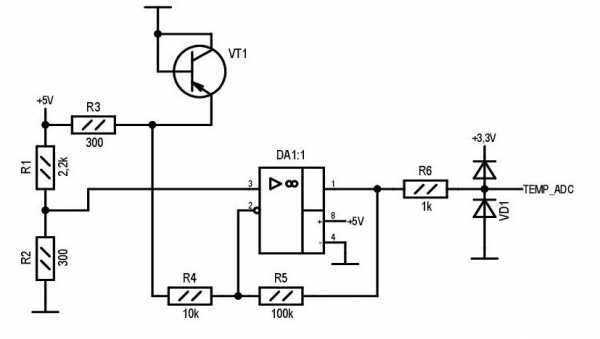
Below is a diagram of switching on a transistor and a signal processing unit on an op-amp. VT1 is the transistor-temperature sensor, which is attached to the radiator.
The transistor is intentionally used in p-n-p structures. the heatsink is often connected to the common wire of the circuit, and the collector of the transistor in the TO-220 package is connected to the heat sink, and when attaching the transistor, there is no need to electrically isolate it from the heatsink, which further simplifies the design.
The voltage drop across the p-n junction changes with an increase in its temperature with a steepness of approximately -2 mV / degree (i.e., decreases with increasing temperature). Such a small voltage change is not very convenient to process the ADC, moreover, it is more convenient when the dependence is direct, i.e. as the temperature increases, the temperature signal increases.
The above circuit biases, inverts and amplifies the signal from the transistor, providing an increase in output voltage with increasing temperature, and works as follows.
From the reference voltage generated by the divider R1R2, the voltage drop across the transistor is subtracted and the result of the subtraction is amplified. The reference voltage is selected just above the voltage drop across the transistor at a temperature of 25 degrees, which ensures that the voltage is measured below 25 degrees.
The gain of the circuit is determined by the ratio R5/R4 + 1 and for this circuit is equal to 11. The final slope of the temperature signal is 2*11=22mV/degree. Thus, to ensure temperature measurement from 0 degrees, the output signal at 25 degrees must be at least 25*0.022=0.55V. The excess of the bias voltage over the drop on the transistor at 25 degrees must be at least 0.05V.
The voltage drop across the transistor at 25 degrees is 0.5-0.6V and depends on the specific type of transistor and the current through it, and it’s probably impossible to select the reference voltage “on the fly”, therefore, at the debugging stage, it is necessary to select resistors R1R2 for a specific type of transistor and current through it, from one transistor to another, this value may change, but this can already be corrected by software methods.
The current through the transistor is determined by the resistance of the resistor R3, in this circuit the current is approximately equal to 15mA. The recommended value of current through the transistor is 10-20mA.
The above circuit is adapted for an ADC with a reference voltage of 3.3V, but can also be used for a 5V reference voltage, for this it is necessary to increase the gain of the circuit, based on the required temperature range.
On the R6VD1 elements, an output voltage limiting circuit is assembled in case of emergency situations, for example, a wire break to the transistor. If the supply voltage of the op-amp does not exceed the reference voltage of the ADC, then they can be excluded.
Any op amp can be used as DA1, providing operation with unipolar power supply and input voltage from 0V. For example, the cheap and common LM358.
As a transistor, any non-composite transistor of a p-n-p structure can be used.