CLAIM
1. A liquid mixer with non-contact control, containing a housing with two inlet and one outlet pipes, shut-off devices with rods moving reciprocating from manual drives combined with rods, characterized in that two proximity sensors are introduced into the device, electromagnets in number inlet branch pipes, the cores of the electromagnets are coaxially connected to the rods and locking elements, and the manual drives are equipped with rod clamps, and the power of the electromagnets is supplied through the power keys introduced into the device, controlled by proximity sensors.
2. The mixer according to claim 1, characterized in that each power switch contains a threshold element connected in series, a leading edge detection element, a single vibrator, a disjunctor and a key amplifier, and the second input of the disjunctor is connected to the output of the threshold element in parallel with the leading edge detection element.
3. The mixer according to claim 1, characterized in that the number of inlet pipes, rods, locking devices, manual drives and power keys is increased to three, and the input of the third power key is connected to the outputs of the threshold elements of the first and second power keys through the five-position input into the device switch, to the first input of which the output of the conjunctor is connected, the outputs of the threshold elements of the first and second power switches, respectively, are connected to the second and third inputs of the switch, the output of the disjunctor is connected to the fourth input of the switch, the fifth input of the switch is connected to the neutral wire, and the inputs of the disjunctor and the conjunctor is connected to the outputs of the threshold elements of the first and second power switches, and the output of the single vibrator of the third power switch is connected to the inputs of the prohibition elements introduced into the first and second power switches between the disjunctors and key amplifiers.
4. The mixer according to claim 1, characterized in that the third power switch contains, in addition to the single vibrator and the key amplifier, an element for adjusting the pulse duration generated by the single vibrator.
5. The mixer according to claim 1, characterized in that the number of inlet pipes, rods, locking devices, manual drives and power keys is increased to four, and the fourth power key contains serially connected conjunctor zero signals from the outputs of the disjunctors of the first and second power keys, a single vibrator and a key amplifier, and a single vibrator contains an element for adjusting the pulse duration.
Double-Gate FETs in a Direct Conversion Receiver Mixer
Rating: / 5
- Details
- Views: 729
Alexander FEDOTOV (RV6AT, ex UA6AHX), Temryuk, Krasnodar Territory During experiments with mixers based on field-effect transistors KP305, most of them failed due to their high sensitivity to static electricity. Therefore, it was decided to conduct experiments with mixers based on double-gate field-effect transistors BF960, BF961, BF964S of foreign production and domestic KP327A. A feature of these transistors is the presence of built-in protective diodes in the gate circuits, so they are resistant to static electricity. The scheme of the mixer range of 80 meters on one transistor is shown in fig. one.
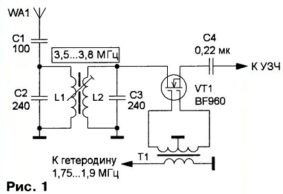 Here, the local oscillator operates at a frequency half that of the received one. This made it possible to significantly attenuate the radiation of the local oscillator signal (up to 80 dB) and practically get rid of the alternating current background caused by such radiation. Without UHF, the sensitivity of a receiver with such a mixer can reach 0.3 μV. The dynamic range of the receiver is about 100 dB.In this case, the local oscillator signal power is low, the mixer starts working at a local oscillator signal voltage of 0.3 V. Signals in the range of 80 meters are emitted by a two-loop filter L1C2L2C3. Since the interelectrode capacitances of the transistor are small, it turned out to be possible to connect it directly to the second circuit. The drain and source can be swapped without any noticeable deterioration in reception quality. In this mixer, you can use any of the above field effect transistors. Transformer T1 is wound on an annular magnetic circuit “10x6x4 made of 400NM ferrite with a triple folded PEL 0.2 wire, the number of turns is from 12 to 18. Coils L1 and L2 are wound turn to turn with PEL 0.2 wire on a common frame with a diameter of 5 mm and contain 42 coil. The distance between the coils is 4 mm, each is adjusted by its “own” trimmer. Using simple RC phase shifters and a good AF filter in the mixer, you can make a direct conversion SSB receiver with unwanted sideband suppression. The scheme of such a mixer is shown in fig. 2.
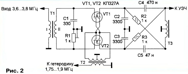 And although the suppression of the unnecessary sideband is not as great as in the Pilgrim direct conversion transceiver receiver, the main advantage of such receivers is preserved here - simplicity and a small number of elements. The HF phase shifter is assembled on the elements R1 and C1, and the LF phase shifter is assembled on the elements R2, R3, C4, C5 and TK. Their joint work provides suppression of unnecessary sideband from 10 to 40 dB. Transformer T1 is wound on a K10x6x4 ring magnetic circuit made of 400NM ferrite with a PEL 0.2 wire folded in half, the number of turns is 20. The design of the T2 transformer is similar to the design of the T1 transformer in the previous mixer. An output transformer (primary winding) from an ultrasonic pocket receiver was used as a transformer TK. It can be wound on a K16x8x4 magnetic core made of 2000NN ferrite. The winding contains 500 turns of doubled PEL 0.1 wire. Since the selectivity of the direct conversion receiver depends mainly on the quality of the 3H filter, you should not save on it.
Entry level HF receiverDirect conversion receiver path with digital IC demodulatorSimple dedicated receiversShortwave observer receiver
Only registered users can leave comments