Pressure, flow and level regulators
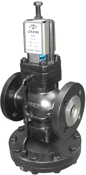
Figure 7
Pressure regulator with mounting flanges
Purpose of regulators
Regulators (reducers) of pressure, flow and level are designed to automatically maintain the corresponding parameter without the use of secondary energy sources.
Regulator design
By design, the regulator is a valve with a pneumatic or hydraulic actuator of a membrane, bellows or plunger type, as well as a special setting spring designed to adjust the regulator to the required parameter value. Regulator designs are extremely diverse.
Level regulators are divided into:
- supply regulators, in which the level is maintained by periodically adding liquid to the vessel, and
- overflow regulators, in which excess liquid is drained.
pressure regulator
Consider pressure regulator
on the example of a gas cylinder reducer. The gas inlet opening is the valve seat, against which the valve disc is pressed, fixed at one end of the angle lever. The second end of the lever is connected to a movable membrane, which is acted on from the outside by the force of atmospheric pressure and the force of compression of the setting spring, and on the other hand by the force of gas pressure in the regulator cavity. The axis of rotation of the lever is fixed on the bottom of the regulator housing. If the pressure of one of the burners of the gas stove is closed, then the gas flow will decrease, as a result of which the gas pressure in the reducer cavity will begin to rise. This will move the membrane, which will pull the end of the lever connected to it. The second end of the lever with the valves attached to it will also move and cover the hole for the passage of gas. As a result, the gas pressure in the reducer cavity will be practically at a constant level, since the valve stroke is extremely small and the force of the setting spring will change slightly when the membrane is moved.
The regulator will ensure the passage of the required gas flow at a constant pressure in front of the burners.
Flow regulator
Figure 7
Direct acting flow regulator with connecting flanges.
Working flow controller
similar to a level controller, maintaining a constant differential pressure across some throttling device, such as a diaphragm or adjustable nozzle. Since the local resistance coefficient of the throttling device does not change, a constant differential pressure means that the flow rate through the choke is constant and therefore the flow rate is constant. Some regulators have a throttle, the design of which allows you to adjust its resistance, adjusting the regulator to the desired flow rate. More often, however, the resistance of the throttling device is left constant, and the compression of the setting spring is changed, which makes it possible to regulate the pressure drop across the choke and, consequently, the flow through the regulator.
In regulators, an important principle is the unloading of the valve from the one-sided pressure of the working medium, which can significantly reduce the effort required to move the working body. The most perfect type of unloading is a two-seated valve design, when the forces acting on two plates are opposite in direction and mutually compensate. However, in this design, the body is more difficult to manufacture the body and it is more difficult to ensure the complete tightness of the closing of the two valves at the same time. Despite such difficulties, this design is very widely used in modern regulators.
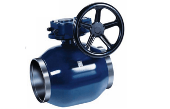
Ball valves feature and use
Ball valves are unique in their design solution. This is a practical modification of the cork faucet.It got its name due to the fact that the cork in its body resembles a ball in shape. Ball valves are designed to control the flow of various types of fluids. Its closing and opening is carried out by turning the handle by one fourth of a turn, which significantly simplifies the work when compared with other types of valves.
When the valve is in the “open” position, the ball hole is parallel to the flow line, which ensures a direct flow with a small degree of friction and minimal pressure loss.
Ball valves are designed specifically for use in the oil and gas industry.
They are practical on pipelines with medium pressure and temperatures not exceeding 200 degrees. Ball valves do not require large production costs when compared with other types of valves. And the tightness when using them is also much higher.
Steel ball valves are considered more versatile, as they have the ability to perform their function even in the presence of low temperature conditions and high pressure.
The following types of ball valves can be distinguished. These are valves made of brass and ball valves made of steel. Brass ball valves are successfully used in the construction industry and housing and communal services. In addition to aqueous media, they are also suitable for low concentration glycol solutions, alcohol, gas and liquid petroleum products. Brass ball valves have a minimum value of 15 millimeters, a maximum of 80.
Steel ball valves are considered more versatile, as they have the ability to perform their function even in the presence of low temperature conditions and high pressure. The minimum value of the nominal diameter of a steel ball valve is the same as that of a brass valve, but the maximum value reaches 500 mm.
No heating system in the modern construction industry is complete without a ball valve design. Ball valves are either coupling, nipple, and flanged. Flanged ball valves, or rather their design, use flanges as elements connecting the valve and the pipeline.
The obvious advantages that flanged ball valves have include:
- low degree of hydraulic resistance;
- various areas of use;
- simple installation and operation.
Cranes, various valves and other valves are a necessary element of any pipeline and are used in various branches of modern industry.
Add to bookmarks
They are used on pipelines larger than 50mm in diameter where slow flow shutoff is required to prevent water hammer.
At the valve, the shutter moves perpendicularly, and at the moment of closing, the sealing surfaces do not experience friction, which significantly reduces the occurrence of scoring.
From-for what inside the valve body, the flow direction changes twice, and the flow area is smaller than that of gate valves, the valve has an increased hydraulic resistance, which is its main disadvantage.
The valve cannot be operated in different directions relative to the flow direction. Its working position is the direction of flow when it presses against the plate in the closed state from the seat side, and not from the stem side. In this position, the flow pressure as the valve opens even helps lift the poppet off the seat. If the valve is not installed correctly, the flow pressure in the closed position presses the poppet, and when the valve is opened, a very significant force will have to be applied to move the stem, since it will be necessary to overcome the flow pressure. This can lead to its failure, since the valve disc can be torn off the stem, which will require a lot of labor for repair.
Principles of operation of a faucet, valve and gate valve
Structural solutions for shutoff valves are taps, valves and gate valves.
How do they differ from each other?
Latches are the most widespread and most demanded locking devices. Their design implies that the locking element is in the closed and open position. The flow of the working medium is blocked due to the fact that the locking element moves perpendicular to its axis. Gate valves can only be used as shut-off valves. They are parallel, wedge and gate.
The valve or valve is able to block the flow of the working medium due to the fact that the device moves parallel to the axis of its movement. It, unlike gate valves, can be used not only as a blocking device, but also as a regulating one, due to the fact that its design will allow you not to completely block the flow of the medium, but partially.
A significant disadvantage is the inability of the valve to respond to changing speed and pressure in the system. Therefore, its scope is pipelines with a relatively constant flow and pressure of the working medium. In addition to regulating and locking devices, there are bypass, mixing, and distribution structures of these mechanisms.
A faucet is another type of shutoff valve. It can be used as a blocking or regulating device. It functions as follows: the locking element, rotating around its axis, moves in the direction perpendicular to the flow of the medium. The locking element is disc-shaped. Due to its rotation around its own axis, the liquid overlaps in a perpendicular direction.
Modern plumbing offers various design solutions for valves, which have their own characteristics. Of course, this entails the presence of distinctive advantages and disadvantages, which appear in different conditions. Therefore, in order to choose the right valves, it is necessary to take into account the design features of the pipeline, as well as the conditions of use and requirements for a particular device. To do this, you need to understand how, for example, a tap differs from a valve, because the difference between them is not so obvious.
Varieties
The cast iron flanged gate valve is available in various versions. Devices are divided into types according to the direction of action - parallel and perpendicular. The latter option is stationary and extends perpendicular to the main flow. Parallel attachments are installed at zero angle and are not obstructive to flow when in standard mode.
There is also a division according to design features - these are gate, ball and wedge-shaped elements. The latter are shut-off valves of a standard type. They are quite effective, have a blocking of the perpendicular type, but are very heavy.
The spherical design is similar to locking household elements of a similar type. The most widely used devices are DU 50 due to their relatively low cost. The flange gate valve DN 100 has a special disc element that shuts off the pipeline with a powerful spring. As a rule, it is installed on oil pipelines and gas networks.
Classification by control method:
-
Handheld devices.
This type is controlled manually by turning a special handle or valve. Despite the need for significant physical effort, they do not require maintenance and rarely fail. -
Electric fittings.
It has a built-in electric motor for control. Blocking of the system is done autonomously, after pressing the button.

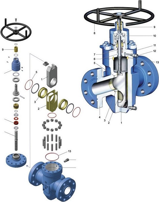
Principle of operation and varieties
The principle of operation of all types of valves is similar to each other.The valve body and cover form a cavity in which the locking unit is placed. Flanges are placed on the body, through which the valve is connected to the pipeline. Depending on the type of connection, the design can be flanged and wafer, which is clamped between the flanges of adjacent sections of the pipeline (wafer gate valve has much smaller dimensions.
Inside the body, next to the locking element, there are two seats (parallel or at a certain angle to each other). The adjustment of the shutter is carried out by rotating the actuator, to which the locking mechanism is connected by means of a stem. Depending on the principle of movement of the stem, the valve can be retractable (the stem performs rotational translational movement when closing) or rotary (exclusively rotational movement).
The stem is installed inside the running nut, this assembly is called a threaded pair. The nut, when the drive rotates, ensures the movement of the locking element in a given direction. When the valve is moved to the closed position, its walls are pressed against the sealing surfaces of the seat, while in the open position the valve completely exits the body bore.
The main classification of valves is carried out depending on the type of locking mechanism, according to which the valves are divided into:
- wedge;
- parallel;
- gate;
- hose.

The shutter has a conical shape; when closing, it enters the saddles located at a given angle to each other and closes the through hole. The wedge, depending on the design, can be rigid or clinket.
The wedge of the rigid type (steel) provides maximum tightness in the closed position, however, the operation of this design may be accompanied by a number of problems associated with the valve jamming due to temperature fluctuations or damage to the sealing surfaces due to corrosion.
The gate valve flanged has a gate, consisting of two located at an angle to each other, which are rigidly connected to each other. This design is highly reliable - it does not jam, the seals are subject to minimal wear and much less effort is required to change the position of the valve. Flanged gate valve is the most common type of ship fittings.
The valve consists of two discs that move between parallel sealing seats. A variation of the parallel design is, in it the locking unit has a similar design, however, the shutter consists of 1 disk.
Slide valves are installed on pipelines with one-way movement of the working medium. Due to the simplicity of the design, it is not able to provide maximum tightness of the ceiling, however, the slide gate is maintainable, which allows the use of such designs in sewage and sewer systems that transport liquids with a high content of mechanical particles.
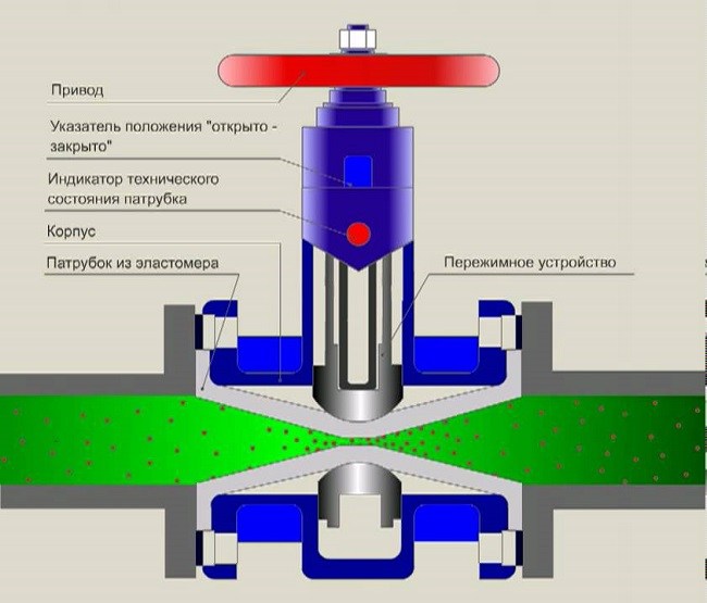
Hose-type valves are fundamentally different from the previously considered counterparts. There are no sealing seats in their design - the working flow circulates inside an elastic rubber hose, which completely isolates the internal surfaces of the body from the transported liquid. The blocking of the flow is carried out by pinching the hose with a rod.
Such designs are intended for installation on pipelines transporting viscous substances and chemically aggressive liquids, under the influence of which accelerated corrosion of steel occurs - rubber is a material that is resistant to most chemical compounds. Operation of these valves is possible at temperatures up to 110 degrees
and working medium pressure up to 1.6 MPa.
This article talks about flanged wedge gate valves, their characteristics, the principle of operation, and most importantly, the use of these products on different pipelines:
Flanged wedge gate valves are in demand in industrial production communications on water, oil, and gas pipelines. They are an indispensable part of any pipeline where it is necessary to block a section or completely the entire pipe. These elements of valves are not complex in design, they have a long service life (up to 50 years). For the safe operation of the pipeline, they are installed at a certain distance from each other so that it is possible to quickly shut off the pipe in case of an accident or repair.
Expert answers
Torbablikh:
So: Let's figure it out: Gate valve. This is a locking device, which has two cheeks that are mirrored to the mirror of the body and, rising from the top or falling from the bottom, due to the movable stem that is screwed into the helm, the valves open or close the water passage. The cheeks are wedge-shaped. The gate valve is open when the top of the stem is fully raised and closed when it is sunk down. Gate valves are available for a pipeline diameter of at least 50 mm. And always with a FLANGE mount.
Valve: This is a shut-off device that also has a handwheel and a stem like a valve, but the handwheel sits dead on the stem, and the stem itself is screwed into the grambox of the valve itself. And at its opposite end sits the so-called pyatak valve with a paronite lining. He closes the valve mirror, thereby blocking the water passage. Valves are both flanged and threaded (according to the type of pipeline connection)
Faucet: This shut-off device works in a completely different way. It has a hollow two-hole body with an internal mirror, to which a bronze cork is mirrored over the entire area, which has an internal hole. When this hole is opposite the holes in the hull cavity, the water passage is open. When the plug is rotated 90 degrees, it closes the waterway. Cranes have only threaded fastening to the pipeline.
But keep in mind that a tap, unlike a valve and a valve, DOES NOT REGULATE the flow of water! It is only rated for FULL OPEN or FULL CLOSE.
Bongiorno Bambini:
The valve is closed and the faucet is closed
A.UMAROV:
The valve has only two positions: open or closed, and the valve can regulate the flow of fluid. Plus the design difference
Artur Eremenko:
Both can block the flow of the working medium. Both gate valves and taps are different, so you need to compare more specifically. Different designs are differently resistant to water hammer. They clog differently, different dimensions and construction lengths, different in terms of maintainability. As a rule, gate valves are cheaper.
Fear:
valve from the word push on in the bottom figure, the purple part pushes and there are a lot of cranes and they are built on different principles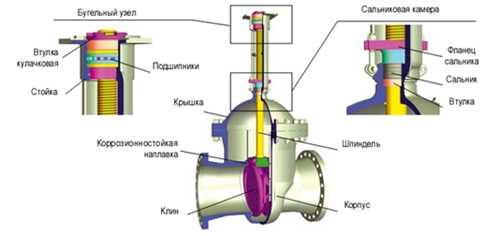
Avotara:
The valve moves in and the valve closes. The valve is more airtight in the closed state than the valve, but has a greater hydrodynamic resistance in the open state (ball valves do not count)
The difference between a valve and a ball valve: a valve can regulate the flow, a ball valve cannot; valves exist for any diameter of pipelines, ball valves only for small ones (due to the huge closing force).
Jurijus Zaksas:
The crane rotates, the valve moves forward. I think so.
dogmet:
The valve can be set as they please, and the current valve as it should)))
Alexander Kuzmin:
The valve has 2 positions - OPEN and CLOSED. The valve can be stopped in any intermediate position.
******:
Two are different in terms of design. The faucet usually has a cone or ball system. And the valve actually repeats the principle of the screw.
yuppie:
Resistant to water hammer, and of course the design.
Alexandr Yyh:
Wikipedia en.wikipedia /wiki/Pipeline_fittings » Types of fittings
According to GOST R 52720-2007 Gate valve is a type of valve in which the locking or regulating element moves perpendicular to the axis of the working medium flow.
A valve (valve) is a type of valve in which the locking or regulating element moves reciprocating parallel to the axis of the flow of the working medium. Valves also include valve structures (rotary valve), in which the valve in the form of a plate moves in an arc.
A valve is a type of valve in which a locking or regulating element in the form of a body of revolution or part of it rotates around its own axis, arbitrarily located in relation to the direction of the flow of the working medium.
Butterfly valve (damper, rotary valve, hermetic valve, hermetic valve) is a type of valve in which the locking or regulating element has the shape of a disk that rotates around an axis perpendicular or at an angle to the direction of the flow of the working medium. »
More on tap and valve en.wikipedia /wiki/Water_faucet en.wikipedia /wiki/Valve
Alexander Osipov:
On the left is a valve, and on the right is a valve. Recently, there has been a tendency to replace old valves with ball valves.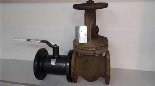
Cranes main characteristics
A faucet differs from a valve and a gate valve in that it is not necessary to rotate the spindle to start or stop the flow with a faucet.
They do not have a stem, and their shutter is made in the form of a ball, cone or cylinder with a hole for the passage of the flow and rotates perpendicular to the flow. If the axis of the valve opening coincides with the axis of the pipeline, then the valve is open, since the flow passes through the hole. If the valve is rotated 90°, the valve will be closed. A faucet differs from a valve and a gate valve in that it does not require the spindle to be rotated to start or stop flow with a faucet. To do this, just turn the shutter by 90 °. This is the difference between a faucet and a gate valve. It does not have a flywheel, so it is powered by a crank. The valve is in the open state if the handle is located along the pipeline, and if it is perpendicular, it is closed.
For cone cranes, the shutter is made according to the type of a truncated cone. It has a hole for the passage of flow in the form of a rectangle or circle. The tap body also has a conical surface. This is done so that the cork can tightly adjoin the saddle.
For tightness, it closes with a lubricant, which must fill all the micro-gaps between the body and the valve. At the same time, it reduces the effort required to turn. The cork is in a pressed state to the surface of the housing.
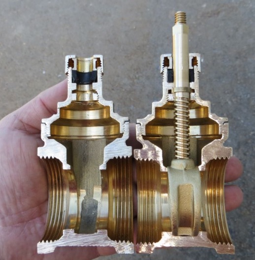
There are two ways to press the shutter, and therefore
Distinguish between stuffing box and tension valves.
In stuffing box valves, between the upper end of the plug and the valve cover, there is a stuffing box packing. This is an elastic element that presses the valve against the body with a constant force. Tension valves have a stem at the bottom of the plug, which passes through the body opening. The shutter is pressed by a spring. Such valves are more reliable, since they do not have stuffing box packing, the elastic properties of which are lost over time. Therefore, in such important industries as gas supply, tension cranes are used.
Cone valves are low cost, they are not difficult to revise, they have a simple design and relatively low hydraulic resistance. This is their advantage.
But such cranes also have disadvantages. It takes a lot of effort to turn the cork. Over time, micro-gaps between the shutter and the body surface become covered with deposits. In this case, a lot of effort is already required to turn the shutter, which can lead to breakage of the crane.
For the production of taps, a high-quality surface of the gate and body is required, so they are made of bronze and brass.In addition, these metals are less susceptible to corrosion, and this prolongs its service life.
Ball valve and valve difference and product features
What is better to buy: a faucet or a device such as a valve? It is really impossible to give a precise answer to this question. Indeed, in some situations it is necessary to use a ball valve, but in others - a special valve. Additionally, it is recommended to note here the fact that the crane is considered a more convenient device to use. In this situation, the handle can be rotated all 90 degrees. Due to this, the incoming water is blocked. But the shut-off valve present in the valve must be wrapped in order to close or open the water supply.
Additionally, there are special valves with gaskets on the valve. When worn out, it is enough to simply replace them with a new version. It is also recommended to periodically replace the seal itself. But with a ball valve variety, such problems do not really exist. Only constant and thorough care of the surface itself is recommended here. It should always be in the most ideal condition.
In general, if enough hard water is supplied to the room, then the installation of a valve is recommended. After all, such a product is subject to, albeit partial, but still repair. In a situation where the crane is damaged for some reason, then you can not do without its full replacement.
With all this, the valve can most often be purchased at a lower cost, if taken in comparison with the second type of product. Such a not too high price is primarily due precisely to the fact that the device has a simple design of such an element as a shut-off valve.
In any situation, the shut-off type of valves in modern times is used to create a variety of sewer and gas pipeline systems. It is also often found in pipelines with a general purpose. The device is intended to block the gas or water flow. For this purpose, it is possible to install not only valves and gate valves, but also devices such as taps and valves. All of them have a huge number of advantages, and some negative characteristics. Everything depends on the situation.
Thus, the difference between a valve and a tap initially lies in the fact that with the use of a tap it is impossible to regulate the pressure of the working flow. But the second product allows such an action.
Shut-off valves are used in the construction of gas and sewer systems. Such devices are noticeable on different types of pipes, their direct purpose is to block any flows (water or gas). The tap and valve are the main mechanisms of this type.
Based on the characteristics of these mechanisms, a certain type of device is selected. To make the right choice, you need to know what works and how.
What is the difference between a faucet and a valve?
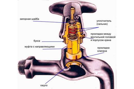
It must be said that neither the tap nor the valve can change the direction of the flow, they are used only when it is necessary to partially or completely block the flow. When installing taps and valves in the pipeline system, you need to look at the arrow - it shows the correct direction of movement. Incorrect installation contributes to excessive hydraulic resistance, which will affect the service life, may lead to incorrect operation and malfunctions. The structure of the valve includes groin-boxes, which allows hermetically sits on the seat of the hole.
There are also visual differences. The handles of these locking devices are different - the valve has a “lamb”, which is necessary for smooth flow control, while the faucet has a simple handle that is attached to the stem
The answer to the question "which is better: a faucet or a valve?" no. It is impossible to give such an answer, since each type of valves is designed to perform certain tasks. The valve, unlike the valve, has design features that contribute to its operation when it is necessary to quickly shut off the flow. This is due to the simpler structure of the handle, as it takes more time to wrap the “lamb” of the valve. In terms of service life, the valve is inferior to the tap; its design assumes sealing elements that periodically break and need to be repaired or replaced. However, in terms of maintainability, the valve has advantages, since in its structure it is possible to replace parts that have failed. If the crane is deformed, a complete replacement is necessary.